EP1547826A2 - Vorrichtung und Verfahren zur Einarbeitung einer Ringantenne und Elektronik in einen Reifen - Google Patents
Vorrichtung und Verfahren zur Einarbeitung einer Ringantenne und Elektronik in einen Reifen Download PDFInfo
- Publication number
- EP1547826A2 EP1547826A2 EP04106690A EP04106690A EP1547826A2 EP 1547826 A2 EP1547826 A2 EP 1547826A2 EP 04106690 A EP04106690 A EP 04106690A EP 04106690 A EP04106690 A EP 04106690A EP 1547826 A2 EP1547826 A2 EP 1547826A2
- Authority
- EP
- European Patent Office
- Prior art keywords
- tire
- antenna assembly
- core
- annular antenna
- annular
- Prior art date
- Legal status (The legal status is an assumption and is not a legal conclusion. Google has not performed a legal analysis and makes no representation as to the accuracy of the status listed.)
- Granted
Links
- 238000000034 method Methods 0.000 title claims abstract description 33
- 238000000465 moulding Methods 0.000 claims description 2
- 238000004513 sizing Methods 0.000 claims 2
- 238000004519 manufacturing process Methods 0.000 description 8
- 239000000853 adhesive Substances 0.000 description 5
- 230000001070 adhesive effect Effects 0.000 description 5
- 239000011324 bead Substances 0.000 description 5
- 239000000463 material Substances 0.000 description 5
- 229910000831 Steel Inorganic materials 0.000 description 3
- 230000000295 complement effect Effects 0.000 description 3
- 239000010959 steel Substances 0.000 description 3
- 238000013459 approach Methods 0.000 description 2
- 238000003780 insertion Methods 0.000 description 2
- 230000037431 insertion Effects 0.000 description 2
- 229910052751 metal Inorganic materials 0.000 description 2
- 239000002184 metal Substances 0.000 description 2
- 238000004073 vulcanization Methods 0.000 description 2
- RYGMFSIKBFXOCR-UHFFFAOYSA-N Copper Chemical compound [Cu] RYGMFSIKBFXOCR-UHFFFAOYSA-N 0.000 description 1
- 229910052782 aluminium Inorganic materials 0.000 description 1
- XAGFODPZIPBFFR-UHFFFAOYSA-N aluminium Chemical compound [Al] XAGFODPZIPBFFR-UHFFFAOYSA-N 0.000 description 1
- 230000015572 biosynthetic process Effects 0.000 description 1
- 238000004891 communication Methods 0.000 description 1
- 239000002131 composite material Substances 0.000 description 1
- 230000001010 compromised effect Effects 0.000 description 1
- 238000010276 construction Methods 0.000 description 1
- 229910052802 copper Inorganic materials 0.000 description 1
- 239000010949 copper Substances 0.000 description 1
- 238000013036 cure process Methods 0.000 description 1
- 230000001419 dependent effect Effects 0.000 description 1
- 238000011161 development Methods 0.000 description 1
- 230000000694 effects Effects 0.000 description 1
- 239000013536 elastomeric material Substances 0.000 description 1
- 230000001788 irregular Effects 0.000 description 1
- 238000003754 machining Methods 0.000 description 1
- 239000000203 mixture Substances 0.000 description 1
- 238000012544 monitoring process Methods 0.000 description 1
- 230000002093 peripheral effect Effects 0.000 description 1
- 239000004033 plastic Substances 0.000 description 1
- 238000007493 shaping process Methods 0.000 description 1
- 239000007787 solid Substances 0.000 description 1
Images


Classifications
-
- B—PERFORMING OPERATIONS; TRANSPORTING
- B60—VEHICLES IN GENERAL
- B60C—VEHICLE TYRES; TYRE INFLATION; TYRE CHANGING; CONNECTING VALVES TO INFLATABLE ELASTIC BODIES IN GENERAL; DEVICES OR ARRANGEMENTS RELATED TO TYRES
- B60C19/00—Tyre parts or constructions not otherwise provided for
-
- B—PERFORMING OPERATIONS; TRANSPORTING
- B60—VEHICLES IN GENERAL
- B60C—VEHICLE TYRES; TYRE INFLATION; TYRE CHANGING; CONNECTING VALVES TO INFLATABLE ELASTIC BODIES IN GENERAL; DEVICES OR ARRANGEMENTS RELATED TO TYRES
- B60C23/00—Devices for measuring, signalling, controlling, or distributing tyre pressure or temperature, specially adapted for mounting on vehicles; Arrangement of tyre inflating devices on vehicles, e.g. of pumps or of tanks; Tyre cooling arrangements
- B60C23/02—Signalling devices actuated by tyre pressure
- B60C23/04—Signalling devices actuated by tyre pressure mounted on the wheel or tyre
- B60C23/0408—Signalling devices actuated by tyre pressure mounted on the wheel or tyre transmitting the signals by non-mechanical means from the wheel or tyre to a vehicle body mounted receiver
-
- B—PERFORMING OPERATIONS; TRANSPORTING
- B60—VEHICLES IN GENERAL
- B60C—VEHICLE TYRES; TYRE INFLATION; TYRE CHANGING; CONNECTING VALVES TO INFLATABLE ELASTIC BODIES IN GENERAL; DEVICES OR ARRANGEMENTS RELATED TO TYRES
- B60C23/00—Devices for measuring, signalling, controlling, or distributing tyre pressure or temperature, specially adapted for mounting on vehicles; Arrangement of tyre inflating devices on vehicles, e.g. of pumps or of tanks; Tyre cooling arrangements
- B60C23/02—Signalling devices actuated by tyre pressure
- B60C23/04—Signalling devices actuated by tyre pressure mounted on the wheel or tyre
- B60C23/0491—Constructional details of means for attaching the control device
- B60C23/0493—Constructional details of means for attaching the control device for attachment on the tyre
-
- H—ELECTRICITY
- H01—ELECTRIC ELEMENTS
- H01Q—ANTENNAS, i.e. RADIO AERIALS
- H01Q1/00—Details of, or arrangements associated with, antennas
- H01Q1/12—Supports; Mounting means
- H01Q1/22—Supports; Mounting means by structural association with other equipment or articles
- H01Q1/2208—Supports; Mounting means by structural association with other equipment or articles associated with components used in interrogation type services, i.e. in systems for information exchange between an interrogator/reader and a tag/transponder, e.g. in Radio Frequency Identification [RFID] systems
- H01Q1/2241—Supports; Mounting means by structural association with other equipment or articles associated with components used in interrogation type services, i.e. in systems for information exchange between an interrogator/reader and a tag/transponder, e.g. in Radio Frequency Identification [RFID] systems used in or for vehicle tyres
-
- B—PERFORMING OPERATIONS; TRANSPORTING
- B29—WORKING OF PLASTICS; WORKING OF SUBSTANCES IN A PLASTIC STATE IN GENERAL
- B29D—PRODUCING PARTICULAR ARTICLES FROM PLASTICS OR FROM SUBSTANCES IN A PLASTIC STATE
- B29D30/00—Producing pneumatic or solid tyres or parts thereof
- B29D30/0061—Accessories, details or auxiliary operations not otherwise provided for
- B29D2030/0072—Attaching fasteners to tyres, e.g. patches, in order to connect devices to tyres
-
- B—PERFORMING OPERATIONS; TRANSPORTING
- B29—WORKING OF PLASTICS; WORKING OF SUBSTANCES IN A PLASTIC STATE IN GENERAL
- B29D—PRODUCING PARTICULAR ARTICLES FROM PLASTICS OR FROM SUBSTANCES IN A PLASTIC STATE
- B29D30/00—Producing pneumatic or solid tyres or parts thereof
- B29D30/0061—Accessories, details or auxiliary operations not otherwise provided for
- B29D2030/0077—Directly attaching monitoring devices to tyres before or after vulcanization, e.g. microchips
Definitions
- the subject invention relates generally to build apparatus and method for applying electronics to a tire for the purpose of monitoring tire condition parameters and, more specifically, to a tire build apparatus and method for incorporating an annular antenna and associated electronics into a tire.
- annular apparatus including an antenna, for electronically transmitting tire or wheel identification or other data at radio frequency.
- the apparatus includes a radio-frequency tag, or transponder, comprising an integrated circuit chip having data capacity at least sufficient to retain identification information for the tire or wheel.
- Other data such as the inflation pressure of the tire or the temperature of the tire or wheel at the transponder location, can be transmitted by the transponder along with the identification data.
- the annular antenna is tire-mounted and transmits, at radio frequencies, data from the transponder to a reader mounted on the wheel assembly.
- the antenna and transponder may be incorporated into a tire during "pre-cure" manufacture of the tire.
- the integrity of the connection between the tire and antenna is greatly enhanced by a pre-cure assembly procedure. In practice, however, it is very difficult to do this.
- Both radial ply and bias ply tires undergo a substantial diametric enlargement during the course of manufacture. Bias ply tires are expanded diametrically when inserted into a curing press, which typically has a bladder that forces the green tire into the toroidal shape of the mold enclosing it.
- an alternative known approach is to assemble the tag and antenna into a separate annular apparatus for post-cure attachment to the tire.
- the annular apparatus may be attached to the tire after the tire is cured by adhesive or other known techniques. While such an approach avoids damaging the tag electronics during tire manufacture, adhesive attachment of the antenna and tag to a tire in a post-cure procedure has certain drawbacks. First, the procedure adds labor, and hence cost, to the manufacturing process. Secondly, the security of the attachment between the annular apparatus and the tire is dependent upon the efficacy of the adhesive system employed. Development of a suitable adhesive that is inexpensive, convenient to use, and durable enough to function throughout the life cycle of a tire has proven problematic.
- a method for pre-cure application of an annular antenna assembly to a tire according to claim 1 is disclosed.
- the method may also comprise the step of assembling the annular antenna assembly on the rigid core.
- the annular antenna assembly may alternatively be assembled on the rigid core from components or pre-assembled off-site and transferred as a unitary assembly to the rigid core.
- a tire mold is provided including a rigid core for the practice of the inventive method.
- a tire manufactured pursuant to the inventive method constitutes yet a further aspect of the invention.
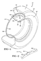
- an annular antenna assembly 10 is shown deployed within a tire 12.
- the tire 12 is formed from conventional materials such as rubber or rubber composites by conventional means and may comprise a radial ply or bias ply configuration.
- a typical tire 12 is configured having a tread 14, a shoulder 16, an annular sidewall 18, and a terminal bead 20.
- An inner liner 22 is formed and defines a tire cavity 24.
- the tire 12 is intended for mounted location upon an annular rim 26 having a peripheral rim flange 28 and an outer rim flange surface 30.
- Rim 26 is conventionally configured and composed of a suitably strong metal such as steel.
- An annular antenna 32 is provided and, in the preferred embodiment, embodies a sinusoidal configuration.
- Antenna 32 may be alternatively configured into alternative patterns or comprise a straight wire(s) if desired and may be filament wire, or cord or stranded wire.
- Acceptable materials for the wire include steel, aluminum, copper or other electrically conducting wire.
- the wire diameter is not generally considered critical for operation as an antenna and multiple strands of fine wire is preferred.
- the curvilinear form of antenna 32 provides flexibility and minimizes the risk of breakage during manufacture and use of the tire.
- a tag carrier 34 of the general type described above is provided and may include means for sensing tire parameters such as pressure and temperature.
- a carrier strip of material 36 formed into the annular configuration shown.
- Carrier strip 36 is formed of electrically insulating, preferably semi-rigid elastomeric material common to industry such as rubber or plastic.
- the strip 36 is formed to substantially encapsulate the antenna wire(s) 32 and at least a portion of the tag carrier 34.
- the apparatus 10 comprises antenna 32, tag carrier 34, and carrier strip 36, in a unitary, generally circular, assembly.
- the diameter of the apparatus assembly 10 is a function of the size of the tire 12.
- the preferred location of the antenna assembly 10 on the tire is on the tire just above the rim flange 30. Such a location minimizes stress forces on the assembly from operation of the tire and minimizes interference to RF communication between the tag and an external reader (not shown) that might otherwise be caused by the metal rim.
- Other mounting locations of the antenna assembly 10 on the tire may be employed if desired for specific tire applications.
- the tire 12 is shown in greater detail.
- the subject invention may be utilized in tires of various construction and size.
- the tire 12 may be a commonly available radial passenger or light truck tire.
- the tire 12 includes a carcass 40 having a tread region 14, a shoulder region 16, and a sidewall region 18 extending from the shoulder 16 to an annular bead 20.
- a ply structure 42 is generally provided within sidewall 18 and one or more belt plies 44, 46 are located at the tread region 14.
- the inner liner 22 represents the interior surface of the tire and extends continuously from the bead, along the sidewall region, and across the tread region.
- a segmented rigid core mold 50 is shown in FIG. 4 by way of example, it being understood that the invention need not be limited to the mold configuration shown.
- the mold 50 includes segments 52 that come into concordance with the side parts 54 via contact surfaces 56, 57.
- Each segment also has transverse contact surfaces (not shown) which in closed position adjoin the transverse faces of the adjacent segments.
- the radially inner faces 58 of the core 48 come, in closed position, into contact with the corresponding faces 60 arranged in the extension 62 of each side part 54 beyond a zone 64 assuring the molding of the radially inner surface of the beads of the tire.
- a cavity is defined between the core 48 and mold segments 52, 54 defined along inward toroidal surfaces to create the structure of the tire to be molded.
- an annular groove or recess 66 is formed within an outward surface of the mold core 48.
- the rigid composition of the core 48 facilitates the creation of an annular recess therein by machining or other known manufacturing techniques.
- the recess 66 is configured and dimensioned to receive antenna assembly 10 therein as shown in FIGS.3, 4.
- the location of recess 66 within core 48 is generally preferred to be a distance nominally one inch above the tire bead, as indicated in FIG. 3. However, other locations may be used at the user's preference.
- the recess 66 is provided with an enlarged socket formed therein configured complementary with the transponder component 34 of the assembly. Any other geometric irregularity that is present within the assembly may be accommodated by the inclusion of a complementary recess or socket within the recess 66.
- the recess 66 preferably extends in a circular path about the core 48, however, a non-circular or irregular path may also be employed.
- the annular recess is sized in a depth dimension to allow the annular assembly 10 to project from the recess 66 a distance beyond the outer surface of core 48 for a purpose explained below. Insertion of the annular assembly 10 within recess 66 core 48 is preferably effected as a step preliminary to the building of the tire carcass 40 upon the core. Insertion of the annular assembly 10 into recess 66 may be accomplished manually or through the use of robotics or other known assembly methods.
- the tire carcass may be built upon the core beginning with the inner liner 22 in conventional fashion. The carcass this entraps and surrounds the annular apparatus within recess 66.
- the annular apparatus 10 may be assembled on the core 48 from components, that is the transponder 34, antenna wire(s) 32, and the cover 36. Alternatively, the assembly 10 may be assembled off site and mounted to the core 48 as a unitary assembly. At the conclusion of the tire build procedure upon core 48, the tire is subjected to a curing cycle in conventional fashion.
- the cover 36 of the assembly 10 is cross-bonded to the inner liner 22 and a strong mechanical connection is established therebetween.
- Protrusion of the assembly 10 from the recess 66 of core 48 enhances the cross-bonded connection between the cover 36 and the inner liner 22 and ensures that the connection is not compromised by the presence of air between the surfaces of cover 36 and inner liner 22.
- the tire 12 is removed from the mold 50 and from core 48 and includes an accurately positioned annular assembly 10 encircling the inner liner 22.
- the transponder 34 is oriented within the recess 66 so that any sensor devices may be directed inward in the finished tire. For example, a pressure sensor may be directed toward and protrude into the cavity 24 of tire 12 if desired.
- the subject invention satisfies the needs of the industry for a convenient, cost-effective, and reliable method for affixing an annular antenna assembly to an inner surface of the tire.
- the location of the annular assembly is easily selected by the user and precisely positions the assembly 10 relative to the tire 12 in a carefully controlled and repeatable manner.
- no additional adhesive or hardware is required to effect the connection between the assembly 10 and tire 12.
- the groove is configured to complement the annular assembly 10, a positive seating of the assembly 10 within the groove 66 is possible. Additional protrusions may be incorporated within assembly cover 36 if desired by which to orient assembly 10 within groove 66.
- the sides of the rigid core 48 defining groove 66 protect the annular assembly 10 during the vulcanization of the tire and damage to the assembly 10 from the forces within the tire during the cure cycle is avoided.
Landscapes
- Engineering & Computer Science (AREA)
- Mechanical Engineering (AREA)
- Moulds For Moulding Plastics Or The Like (AREA)
- Tires In General (AREA)
- Heating, Cooling, Or Curing Plastics Or The Like In General (AREA)
Applications Claiming Priority (2)
| Application Number | Priority Date | Filing Date | Title |
|---|---|---|---|
| US53191003P | 2003-12-23 | 2003-12-23 | |
| US531910P | 2003-12-23 |
Publications (3)
| Publication Number | Publication Date |
|---|---|
| EP1547826A2 true EP1547826A2 (de) | 2005-06-29 |
| EP1547826A3 EP1547826A3 (de) | 2006-02-08 |
| EP1547826B1 EP1547826B1 (de) | 2008-01-02 |
Family
ID=34549617
Family Applications (1)
| Application Number | Title | Priority Date | Filing Date |
|---|---|---|---|
| EP04106690A Expired - Lifetime EP1547826B1 (de) | 2003-12-23 | 2004-12-17 | Vorrichtung und Verfahren zur Einarbeitung einer Ringantenne und Elektronik in einen Reifen |
Country Status (6)
| Country | Link |
|---|---|
| US (1) | US20050133132A1 (de) |
| EP (1) | EP1547826B1 (de) |
| JP (1) | JP4559837B2 (de) |
| BR (1) | BRPI0405748A (de) |
| CA (1) | CA2489221A1 (de) |
| DE (1) | DE602004011011T2 (de) |
Families Citing this family (15)
| Publication number | Priority date | Publication date | Assignee | Title |
|---|---|---|---|---|
| US6978669B2 (en) * | 2003-12-22 | 2005-12-27 | The Goodyear Tire & Rubber Company | Method and assembly of sensor ready tires |
| US7250914B2 (en) * | 2004-07-30 | 2007-07-31 | The Goodyear Tire & Rubber Company | Composite antenna for a tire |
| US7492328B2 (en) | 2004-07-30 | 2009-02-17 | The Goodyear Tire & Rubber Company | Composite antenna for a tire |
| US7284417B2 (en) * | 2005-07-28 | 2007-10-23 | Reynolds Charles W | Tire monitor |
| JP4574545B2 (ja) * | 2005-12-28 | 2010-11-04 | 住友ゴム工業株式会社 | タイヤ用無線タグ装着部材、空気入りタイヤならびに空気入りタイヤとリムとの組立体 |
| JP4891727B2 (ja) * | 2006-10-11 | 2012-03-07 | 住友ゴム工業株式会社 | 空気入りタイヤの製造方法 |
| US7903038B2 (en) * | 2006-12-08 | 2011-03-08 | Lockheed Martin Corporation | Mobile radar array |
| US20110041309A1 (en) * | 2009-08-24 | 2011-02-24 | Peter Ross Shepler | Method of installing tire electronics in a tire |
| JP6681479B2 (ja) * | 2016-04-19 | 2020-04-15 | ブリヂストン アメリカズ タイヤ オペレーションズ、 エルエルシー | 補強コードアンテナを有する電子デバイスを備えたタイヤ |
| DE102018114616A1 (de) | 2017-06-20 | 2018-12-20 | Turck Holding Gmbh | Gummireifen mit Transponderanordnung |
| DE102018200103A1 (de) * | 2018-01-05 | 2019-07-11 | Continental Reifen Deutschland Gmbh | Reifenbauteil für einen Reifenrohling |
| KR102080442B1 (ko) * | 2019-06-28 | 2020-02-21 | 한국타이어앤테크놀로지 주식회사 | 전자장치가 일체화된 타이어 및 이의 제조방법 |
| DE102020211103A1 (de) * | 2020-09-03 | 2022-03-03 | Contitech Luftfedersysteme Gmbh | Verfahren und Vorrichtung zur Herstellung eines Luftfederbalgs |
| KR102520667B1 (ko) * | 2021-09-29 | 2023-04-13 | 넥센타이어 주식회사 | 전자 장치를 가지는 타이어 및 이의 제조 방법 |
| KR102598509B1 (ko) * | 2021-10-07 | 2023-11-07 | 넥센타이어 주식회사 | 타이어 |
Family Cites Families (11)
| Publication number | Priority date | Publication date | Assignee | Title |
|---|---|---|---|---|
| US3662335A (en) * | 1969-10-08 | 1972-05-09 | Kurt Fritze | Device for road vehicles for the wireless transmission of at least one measured value of a rotating wheel to an indicating instrument |
| US4305446A (en) * | 1977-11-30 | 1981-12-15 | The Goodyear Tire & Rubber Company | Cast tire and method of manufacture |
| FR2597783B1 (fr) * | 1986-04-25 | 1988-08-26 | Michelin & Cie | Moule rigide pour le moulage et la vulcanisation de pneumatiques |
| US5479171A (en) * | 1993-04-27 | 1995-12-26 | Texas Instruments Deutschland Gmbh | Extended range RF-ID transponder |
| US5500065A (en) * | 1994-06-03 | 1996-03-19 | Bridgestone/Firestone, Inc. | Method for embedding a monitoring device within a tire during manufacture |
| CA2312153A1 (en) * | 1997-12-09 | 1999-06-17 | The Goodyear Tire & Rubber Company | Antenna for radio transponder |
| JP4298922B2 (ja) * | 1998-08-03 | 2009-07-22 | ザ・グッドイヤー・タイヤ・アンド・ラバー・カンパニー | 空気入りタイヤ内へのトランスポンダの取り付け |
| FR2817509B1 (fr) * | 2000-12-05 | 2003-08-29 | Trw France | Systeme de mesure de parametres de roue et detecteur de mesure pour un tel systeme |
| JP4052290B2 (ja) * | 2003-08-29 | 2008-02-27 | オムロン株式会社 | 無線icタグ接合方法、無線icタグ付き物品、及び車両 |
| US7017405B2 (en) * | 2003-12-22 | 2006-03-28 | The Goodyear Tire & Rubber Company | System and method for post-cure application of electronics to a tire |
| US7104298B2 (en) * | 2003-12-22 | 2006-09-12 | The Goodyear Tire & Rubber Company | Tire having antenna attached to elastic fiber textile strip and method of mounting antenna assembly to tire |
-
2004
- 2004-02-12 US US10/777,366 patent/US20050133132A1/en not_active Abandoned
- 2004-12-03 CA CA002489221A patent/CA2489221A1/en not_active Abandoned
- 2004-12-10 JP JP2004357654A patent/JP4559837B2/ja not_active Expired - Fee Related
- 2004-12-16 BR BR0405748-1A patent/BRPI0405748A/pt not_active IP Right Cessation
- 2004-12-17 EP EP04106690A patent/EP1547826B1/de not_active Expired - Lifetime
- 2004-12-17 DE DE602004011011T patent/DE602004011011T2/de not_active Expired - Fee Related
Also Published As
| Publication number | Publication date |
|---|---|
| EP1547826A3 (de) | 2006-02-08 |
| JP4559837B2 (ja) | 2010-10-13 |
| BRPI0405748A (pt) | 2005-08-09 |
| CA2489221A1 (en) | 2005-06-23 |
| DE602004011011T2 (de) | 2008-12-18 |
| JP2005178746A (ja) | 2005-07-07 |
| EP1547826B1 (de) | 2008-01-02 |
| DE602004011011D1 (de) | 2008-02-14 |
| US20050133132A1 (en) | 2005-06-23 |
Similar Documents
| Publication | Publication Date | Title |
|---|---|---|
| CN110035914B (zh) | 用于轮胎的射频通信模块 | |
| EP1547826B1 (de) | Vorrichtung und Verfahren zur Einarbeitung einer Ringantenne und Elektronik in einen Reifen | |
| CN110035911B (zh) | 用于轮胎的射频通信模块 | |
| US6978669B2 (en) | Method and assembly of sensor ready tires | |
| EP3632705B1 (de) | Reifen und reifenherstellungsverfahren | |
| EP1550568B1 (de) | System und Verfahren zur Anordnung von Elektronik auf einem Reifen nach der Aushärtung | |
| US8142600B2 (en) | Method for mounting a tag in a tire sidewall | |
| EP3756909B1 (de) | Reifen versehem mit einer elektronischen gerät und herstellungsverfahren dafür | |
| CN112154059B (zh) | 生产设置有射频通信模块的轮胎的方法 | |
| EP3632666A1 (de) | Reifenherstellungsverfahren | |
| EP3653406B1 (de) | Reifen | |
| JP7666917B2 (ja) | 埋め込まれて封入されたタイヤセンサユニット | |
| US20250367985A1 (en) | Antenna connection for integrated rfid tag and tpms sensor | |
| US7736454B2 (en) | Method for incorporating an annular antenna and electronics into a tire | |
| EP4364970B1 (de) | Runderneuerter reifen und herstellungsverfahren für runderneuerten reifen | |
| EP4442446A1 (de) | Reifenherstellungsverfahren mit darauf angebrachtem drahtloskommunikationsetikett-belagsmodul mit kurzer reichweite und dadurch hergestellter reifen |
Legal Events
| Date | Code | Title | Description |
|---|---|---|---|
| PUAI | Public reference made under article 153(3) epc to a published international application that has entered the european phase |
Free format text: ORIGINAL CODE: 0009012 |
|
| AK | Designated contracting states |
Kind code of ref document: A2 Designated state(s): AT BE BG CH CY CZ DE DK EE ES FI FR GB GR HU IE IS IT LI LT LU MC NL PL PT RO SE SI SK TR |
|
| AX | Request for extension of the european patent |
Extension state: AL BA HR LV MK YU |
|
| PUAL | Search report despatched |
Free format text: ORIGINAL CODE: 0009013 |
|
| AK | Designated contracting states |
Kind code of ref document: A3 Designated state(s): AT BE BG CH CY CZ DE DK EE ES FI FR GB GR HU IE IS IT LI LT LU MC NL PL PT RO SE SI SK TR |
|
| AX | Request for extension of the european patent |
Extension state: AL BA HR LV MK YU |
|
| 17P | Request for examination filed |
Effective date: 20060808 |
|
| AKX | Designation fees paid |
Designated state(s): DE FR GB IT |
|
| 17Q | First examination report despatched |
Effective date: 20061123 |
|
| GRAP | Despatch of communication of intention to grant a patent |
Free format text: ORIGINAL CODE: EPIDOSNIGR1 |
|
| GRAS | Grant fee paid |
Free format text: ORIGINAL CODE: EPIDOSNIGR3 |
|
| GRAA | (expected) grant |
Free format text: ORIGINAL CODE: 0009210 |
|
| AK | Designated contracting states |
Kind code of ref document: B1 Designated state(s): DE FR GB IT |
|
| REG | Reference to a national code |
Ref country code: GB Ref legal event code: FG4D |
|
| REF | Corresponds to: |
Ref document number: 602004011011 Country of ref document: DE Date of ref document: 20080214 Kind code of ref document: P |
|
| PLBE | No opposition filed within time limit |
Free format text: ORIGINAL CODE: 0009261 |
|
| STAA | Information on the status of an ep patent application or granted ep patent |
Free format text: STATUS: NO OPPOSITION FILED WITHIN TIME LIMIT |
|
| 26N | No opposition filed |
Effective date: 20081003 |
|
| PGFP | Annual fee paid to national office [announced via postgrant information from national office to epo] |
Ref country code: FR Payment date: 20081205 Year of fee payment: 5 |
|
| PGFP | Annual fee paid to national office [announced via postgrant information from national office to epo] |
Ref country code: DE Payment date: 20081230 Year of fee payment: 5 |
|
| GBPC | Gb: european patent ceased through non-payment of renewal fee |
Effective date: 20081217 |
|
| PG25 | Lapsed in a contracting state [announced via postgrant information from national office to epo] |
Ref country code: GB Free format text: LAPSE BECAUSE OF NON-PAYMENT OF DUE FEES Effective date: 20081217 |
|
| REG | Reference to a national code |
Ref country code: FR Ref legal event code: ST Effective date: 20100831 |
|
| PG25 | Lapsed in a contracting state [announced via postgrant information from national office to epo] |
Ref country code: FR Free format text: LAPSE BECAUSE OF NON-PAYMENT OF DUE FEES Effective date: 20091231 |
|
| PG25 | Lapsed in a contracting state [announced via postgrant information from national office to epo] |
Ref country code: DE Free format text: LAPSE BECAUSE OF NON-PAYMENT OF DUE FEES Effective date: 20100701 |
|
| PG25 | Lapsed in a contracting state [announced via postgrant information from national office to epo] |
Ref country code: IT Free format text: LAPSE BECAUSE OF NON-PAYMENT OF DUE FEES Effective date: 20081217 |