EP1547732A1 - Robotervorrichtung und steuerverfahren dafür - Google Patents
Robotervorrichtung und steuerverfahren dafür Download PDFInfo
- Publication number
- EP1547732A1 EP1547732A1 EP03799175A EP03799175A EP1547732A1 EP 1547732 A1 EP1547732 A1 EP 1547732A1 EP 03799175 A EP03799175 A EP 03799175A EP 03799175 A EP03799175 A EP 03799175A EP 1547732 A1 EP1547732 A1 EP 1547732A1
- Authority
- EP
- European Patent Office
- Prior art keywords
- state
- robot apparatus
- motion
- equation
- robot
- Prior art date
- Legal status (The legal status is an assumption and is not a legal conclusion. Google has not performed a legal analysis and makes no representation as to the accuracy of the status listed.)
- Withdrawn
Links
Images


Classifications
-
- B—PERFORMING OPERATIONS; TRANSPORTING
- B62—LAND VEHICLES FOR TRAVELLING OTHERWISE THAN ON RAILS
- B62D—MOTOR VEHICLES; TRAILERS
- B62D57/00—Vehicles characterised by having other propulsion or other ground- engaging means than wheels or endless track, alone or in addition to wheels or endless track
- B62D57/02—Vehicles characterised by having other propulsion or other ground- engaging means than wheels or endless track, alone or in addition to wheels or endless track with ground-engaging propulsion means, e.g. walking members
- B62D57/032—Vehicles characterised by having other propulsion or other ground- engaging means than wheels or endless track, alone or in addition to wheels or endless track with ground-engaging propulsion means, e.g. walking members with alternately or sequentially lifted supporting base and legs; with alternately or sequentially lifted feet or skid
-
- B—PERFORMING OPERATIONS; TRANSPORTING
- B62—LAND VEHICLES FOR TRAVELLING OTHERWISE THAN ON RAILS
- B62D—MOTOR VEHICLES; TRAILERS
- B62D57/00—Vehicles characterised by having other propulsion or other ground- engaging means than wheels or endless track, alone or in addition to wheels or endless track
- B62D57/02—Vehicles characterised by having other propulsion or other ground- engaging means than wheels or endless track, alone or in addition to wheels or endless track with ground-engaging propulsion means, e.g. walking members
Definitions
- the present invention relates to a robot apparatus having at least a plurality of movable legs, and a control method for the robot apparatus, and particularly, to a robot apparatus that executes locomotion generation and adaptive control by using a predetermined dynamic model, and a control method for the robot apparatus.
- the present invention relates to a robot apparatus that generates a motion pattern, including a walking pattern, in an actual apparatus in real time, and a control method for the robot apparatus, and even more particularly, to a robot apparatus that properly controls the walking while ensuring the consistency between dynamic models for walking-pattern generation and various adaptive control operations, and a control method for the robot apparatus.
- robot A mechanical apparatus, which makes motions similar to human motions by using an electrical or magnetic effect, is called a “robot”. It is said that the term “robot” is originated from a Slavic word “ROBOTA” (a slave machine)".
- ROBOTA a slave machine
- Legged mobile robots that emulate the bodily mechanisms and motions of human beings are particularly called "human type” or “human style” robots (humanoid robots).
- humanoid robots are able to perform life support, that is, to support human activities in living environments and other situations in everyday life.
- the majority of the proposals concerning stable attitude control and falling prevention during walking use the ZMP (Zero Moment Point) as the criterion of determining the walking stability.
- the verification criterion of the stability using the ZMP is based on "the d'Alembert's principle" that the gravitational force and inertial force acting from the walking system to the road, and the moments thereof are counterbalanced by the floor reactive force serving as the reactive force acting from the floor to the walking system, and the floor reactive moment.
- the zero moment point lies on a side of a supporting polygon (i.e., ZMP stable area) defined by contact points of the soles with the road, and the road surface, or on the inner side thereof.
- the ZMP criterion states that "the robot can stably walk without falling down (the robot body does not turn) when the ZMP exists inside the supporting polygon defined by the feet and the road surface at any moment during walking, and a force for pushing the robot against the road surface acts".
- a motion pattern (ex., a two-legged walking pattern) generated based on the ZMP criterion has the advantages, such as pre-settable sole contact points with the road surface and ease in taking account of the kinematic constraint conditions of the leg tips in conformity to the road surface shape. Moreover, since the use of the ZMP as the criterion for determining the stability means that the force is not used as a target value in motion control, but the trajectory is used, technical practicability is enhanced.
- a legged mobile robot disclosed in Japanese Unexamined Patent Application Publication No. H-5-305579 performs stable walking so that a point on the floor surface where ZMP is zero is controlled to coincide with a target value.
- the ZMP is designed to be positioned inside a supporting polyhedron (polygon) or at least at a certain distance from the end of the supporting polygon when the leg touches or leaves the floor. In this case, the walking stability of the robot body is enhanced even under disturbance or the like because of the ZMP positioned at the given distance.
- Japanese Unexamined Patent Application Publication No. H-5-305583 discloses that the walking speed of a legged mobile robot is controlled depending on the target ZMP position. That is, according to preset walking pattern data, the leg joints are driven to bring the ZMP into coincidence with the target position. Moreover, the tilt of the upper body is detected, and the output speed of the preset walking pattern data is changed depending on the detected value. For example, if the robot tilts forward as it tramps on unexpected irregularities, the output speed may be increased to recover its attitude. Also, since the ZMP is controlled to coincide with the target position, the output speed can be changed without any trouble during a double-leg support phase.
- Japanese Unexamined Patent Application Publication No. H-5-305585 discloses that the landing position of a legged mobile robot is controlled by the ZMP target position. That is, the legged mobile robot disclosed in this publication achieves stable walking by detecting a difference between the ZMP target position and the actually measured position, and driving one or both of the legs to cancel the difference, or, alternatively, detecting the moment about the ZMP target position and driving the legs to reduce the moment to zero.
- Japanese Unexamined Patent Application Publication No. H-5-305586 discloses controlling the tilting attitude of a legged mobile robot by the ZMP target position. That is, the moment about the ZMP target position is detected, and the legs are driven to reduce the moment to zero, thereby achieving stable walking.
- Japanese Unexamined Patent Application Publication No. H-10-86081 discloses a method in which several walking patterns each corresponding to one step are prepared off-line, and they are mixed and connected. However, it is impossible to cover all possible walking patterns, which can be said to be innumerable.
- An object of the present invention is to provide a superior robot apparatus that can properly generate motion patterns including a walking pattern in an actual apparatus thereof and in real time, and a control method for the robot apparatus.
- Another object of the present invention is to provide a robot apparatus that can execute proper walking control while ensuring a consistent dynamic model for the generation of a walking pattern and various adaptive control operations, and a control method for the robot apparatus.
- a further object of the present invention is to provide a superior robot apparatus that can properly control the stabilization of a robot body in an embedded CPU having limited calculation resources, and a control method for the robot apparatus.
- a still further object of the present invention is to provide a superior robot apparatus that can enhance the walking performance while sharing a consistent dynamic model constructed in consideration of mutual interference by adaptive control functions, and a control method for the robot apparatus.
- the present invention has been made in view of the above problems, and provides a robot apparatus having a moving means, the robot apparatus including: a state detecting means for detecting the quantity of state of the robot apparatus; a real-time equation-of-motion solving means for finding a solution to an equation of motion with a boundary condition concerning the quantity of state of the robot apparatus; a boundary-condition setting means for setting the current quantity of state detected by the state detecting means as a boundary condition of the equation of motion with a boundary condition; a target-quantity-of-state calculating means for calculating the next-moment target quantity of state of the robot apparatus according to the solution to the equation of motion found by the real-time equation-of-motion solving means under the set boundary condition; and a motion-pattern generating means for generating a motion pattern of the robot apparatus on the basis of the target quantity of state.
- the robot apparatus of the present invention has a real-time general-motion reconfiguring function that immediately meets motion change requests from a user program while maintaining a dynamic balance, information about the real world, such as the present actual state of the robot, actual environmental shapes, and external force, can be reflected.
- both the calculation for generating a motion pattern, such as a walking pattern, and the stabilizing calculation can be made in one calculating operation for reconfiguring the real-time motion of the whole body.
- the equation of motion of the robot is expressed in a simple form, it is a variable coefficient differential equation, and it is not easy to find an analytic solution. Accordingly, a model is made in which a plurality of relatively short time periods are connected, and each of the short periods is approximately expressed by a simple ordinary differential equation under given assumptions, thereby simplifying the calculation. For example, for easy handling, the short periods may be separated on the boundaries between one-leg support phases and double-leg support phases.
- the current quantity of state refers to the quantity of state of the robot apparatus in the present control cycle
- the next-moment target quantity of state refers to the target quantity of state of the robot apparatus in the next control cycle.
- the state detecting means may use the position of the center of gravity of the robot or an N-th order differential value of the position of the center of gravity as the quantity of state of the robot apparatus.
- the state detecting means may use the position of a part adjacent to the center of gravity of the robot or an N-th order differential value of the position of the part as the quantity of state of the robot apparatus.
- two-dimensional state vectors [x, dx/dt] T composed of the position of the center of gravity x of the body and the speed of the center of gravity dx/dt may be used as the quantity of state of the robot apparatus.
- the real-time equation-of-motion solving means may use the ZMP equation of the robot as the equation of motion.
- the moving means is a leg including movable parts and links.
- a real-time trajectory generating means for calculating a trajectory of the position or orientation of a leading-end link of the links in the leg in each control cycle, and an environmental-state measuring means for measuring the state of an environment around the robot apparatus.
- the real-time trajectory generating means can calculate the position and orientation of the leading-end link on the basis of the actual environmental state measured by the environmental-state measuring means, and the motion-pattern generating means can generate a motion pattern of the robot apparatus on the basis of the position and orientation of the leading-end link and the target quantity of state.
- the robot apparatus of the present invention may further include an external-force detecting means for measuring the external force or external moment acting on the actual robot.
- the real-time equation-of-motion solving means can find the solution to the equation of motion in consideration of the external force or moment calculated by the external-force detecting means.
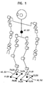
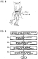
- FIG. 1 schematically shows the degree-of-freedom system in a legged mobile robot that carries out the present invention.
- a robot shown in the figure is a humanoid robot having two legs and two arms.
- the robot has a body with four limbs attached thereto, and includes right and left arms each having seven degrees of freedom of a shoulder joint pitching axis, a shoulder joint rolling axis, an upper-arm yawing axis, an elbow joint pitching axis, a forearm yawing axis, a wrist rolling axis, and a wrist pitching axis, and right and left legs each having six degrees of freedom of a hip joint yawing axis, a hip joint rolling axis, a hip joint pitching axis, a knee pitching axis, an ankle pitching axis, and an ankle rolling axis.
- the degrees of freedom of the joints are, in reality, realized by actuator motors.
- small AC servo actuators in which the gears are directly linked and a servo control system in the form a single chip is contained in a motor unit are mounted.
- This type of AC servo actuator is disclosed in, for example, Japanese Unexamined Patent Application Publication No. 2000-299970 (Japanese Patent Application No. 11-33386) which is assigned to the applicant of the present application.
- An acceleration sensor A1 and a gyroscope G1 are mounted in the body.
- One-axis load cells (F1 to F8) for detecting the floor reactive force in a direction perpendicular to the sole surface and infrared ranging sensors (D1 to D8) for measuring the distance to the floor surface are mounted at the four corners of the right and left soles, four of the load cells and four of the sensors for the right sole, and the other four load cells and the other four sensors for the left sole.
- Acceleration sensors (A2 and A3) and gyroscopes (G2 and G3) are mounted at the centers of the right and left soles.
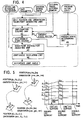
- FIG. 2 schematically shows the functional configuration of a locomotion control system applied to the legged mobile robot of this embodiment.
- the locomotion control system includes a robot-state observing unit 21, an environmental-shape observing unit 22, an external-force and external-moment observing unit 23, a real-time walking-pattern generating unit 25, an upper-limb and lower-limb motion request input unit 24, and a whole-body joint driving unit 26.
- the robot-state observing unit 21 measures the actual quantity of motion state of the robot on the basis of information from various sensors (described above) mounted at the portions of the body, and outputs the measurement result to the real-time walking-pattern generating unit 25.
- the environmental-shape observing unit 22 calculates the environmental shapes, such as the inclination of the road surface and the height of steps, on the basis of information from various sensors (described above), and outputs the calculation result to the real-time walking-pattern generating unit 25.
- the external-force and external-moment observing unit 23 calculates the external force and external moment externally acting on the robot, mainly on the basis of information from force sensors and acceleration sensors mounted on the robot, and reflects the calculation result in the real-time walking-pattern generating unit 25.
- the upper-limb and lower-limb motion request input unit 24 inputs gait parameters concerning motion requests to the upper limbs and motion requests to the lower limbs, such as the stride, walking cycle, and turn angle, sequentially determined according to a user program, and outputs the parameters to the real-time walking-pattern generating unit 25.
- the real-time walking-pattern generating unit 25 determines the motion state of the robot at the next moment which maintains a dynamic balance under the external force detected by the external-force and external-moment observing unit 23, to which a smooth transition can be made from the present motion state of the robot, and which can satisfy the kinematic constraints concerning the environmental shapes and the requests from the user program to change the motions of the upper and lower limbs, and outputs the reference values of joint angles in the whole body.
- the whole-body joint driving unit 26 drives the actuator motors (described above), which define the degrees of freedom of the joints, by a servo controller (not shown) so as to realize the reference joint angles output from the real-time walking-pattern generating unit 25.
- FIG. 3 is a flowchart showing the flow of processing in the locomotion control system shown in FIG. 2.
- the locomotion control system operates in a control cycle of, for example, 10 milliseconds.
- motion requests to the upper and lower limbs are accepted by the upper-limb and lower-limb motion request input unit 24 in Step S1.
- requests to the upper limbs are given as reference values of the joint angles
- requests to the lower limbs are given as gait parameters such as the stride, walking cycle, and turning angle.
- Step S2 state vectors indicating the actual motion state of the robot are calculated by the robot-state observing unit 21 on the basis of information from various sensors.
- the environmental shapes such as the irregularities and inclination of the road surface, are calculated by the environmental-shape observing unit 22 on the basis of information from various sensors (Step S3).
- Step S4 external forces and external moments applied to the parts of the robot are measured on the basis of the values from the force sensors and the like by the external-force and external-moment observing unit 23.
- the motion of the entire robot is reconfigured by the real-time walking-pattern generating unit 25 so as to maintain a dynamic balance while reflecting the present state of the robot, the environmental shapes, the applied external force, and the motion change requests from the user (Step S5).
- the above processing is generally performed in one cycle of the system.
- An operation of returning to Step S1 after the completion of the processing is performed in each control cycle ⁇ t.
- the locomotion control system of this embodiment is characterized in having a real-time general-motion reconfiguring function that immediately meets the motion change request from the user program while maintaining the dynamic balance, and in reflecting information about the real world, such as the actual present state of the robot, actual environmental shapes, and external force, in that function.
- both the walking-pattern generating calculation and the stabilizing calculation can be made in one operation of real-time general-motion reconfiguring calculation by inputting the actual state of the robot, actual environmental shapes, and external force as boundary values and constraint conditions in the real-time general-motion reconfiguring calculation, without separately performing a stabilizing calculation for adapting to unknown environments.
- FIG. 4 schematically shows the internal configuration of the real-time walking-pattern generating unit 25.
- the real-time walking-pattern generating unit 25 includes a sole position and orientation trajectory generating unit 41, a ZMP-equation solving unit 42, a mass-point distribution adjusting unit 43, a joint-angle calculating unit 44, and a present-state determining unit 45.
- the reference upper-limb trajectory and the gait parameters from the upper-limb and lower-limb motion request input unit 24 , the environmental shapes from the environmental-shape observing unit 22, the external force and external moment from the external-force and external-moment observing unit 23, and the present actual state from the robot-state observing unit 21 are input to the real-time walking-pattern generating unit 25.
- Gait parameters such as the stride, walking cycle, turning angle, and lifting height of the leg, concerning the requested motion of the lower limbs
- environmental shapes such as the height and inclination of the road surface, obtained from the environmental-shape observing unit 22 are input to the sole position and orientation trajectory generating unit 41.
- the sole position and orientation trajectory generating unit 41 calculates the position and orientation trajectories of the right and left soles between the previous landing state and a subsequent state several steps ahead.
- FIG. 5 shows the position and orientation trajectories of the soles.
- the positions are expressed by the coordinate positions (x, y, and z), and the orientations are expressed by the Euler angles ( ⁇ , ⁇ , and ⁇ ).
- the trajectories of the right and left soles are formed by generating a time sequence corresponding to each of the gait parameters, for example, by polynomial interpolation so as to match the gait parameters and the environmental shapes.
- interpolation expressions for example, 5th- order polynomial expressions may be used.
- the sole positions and orientations at the second and subsequent steps are similarly formed by interpolation expressions on the assumption that the same walking and environmental conditions as those for the first step are continued.
- the ZMP-equation solving unit 42 calculates robot state vectors after a period ⁇ t that satisfy these conditions while maintaining a dynamic balance.
- the state vectors are defined by the position and speed of the center of gravity in the ZMP-equation solving unit 42.
- the mass of the robot is designated by m
- An arbitrary point p (p x , p y , p z ) T is given in the inertial coordinate system, and a moment generated around p is designated as M.
- Expression 5 is expressed in a simple form, it is a variable coefficient differential equation with respect to x and y. It is not easy to find an analytic solution. In this embodiment, it is assumed that the following approximations are made in a relatively short period T:
- the ZMP equation is a nonlinear equation. Therefore, a heavy calculation load is imposed to solve the equation, and the calculation time is long. Since the locomotion control system of this embodiment aims to control the walking of the actual robot in real time, real-time processability is ensured by making linear approximation in each of the divided periods.
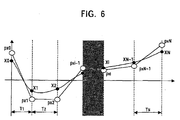
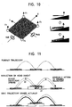
- FIG. 6 shows a walking model in which N-number-of short periods that satisfy the assumption conditions Assumption 1 to Assumption 3 are connected.
- the short periods are separated on the boundaries between one-leg support phases and double-leg support phases.
- n y is fixed in all the periods.
- the present-state vectors (the position and speed of the center of gravity in this embodiment) output from the present-state determining unit 45 are substituted for the position and speed of the center of gravity in the start condition.
- the solution to the ZMP equation is thereby restrained so that the position and speed continue to the present state.
- the center positions of both the soles are set based on the positions of both the soles at the end of the walking period obtained by the sole position and orientation trajectory generating unit 41.
- the speed in the end condition is set, for example, 0 is substituted, on the assumption that the center of gravity is fixed at the position of the center of gravity.
- the solution to the ZMP equation is thereby restrained so that the center of gravity is placed right on the centers of the both soles at the end of the walking period after several steps are made.
- the variables are treated as a problem of optimization.
- Expression 13 to Expression 18 may be solved as 2N+2-element simultaneous equations while the ZMP position is fixed at the position of the center of gravity of the landing polygon in the periods other than specific periods j and k ⁇ [1, N] , and only p xj and p xk are set as variables.
- the intermediate motion state can be calculated by using Expression 9 so as to make a smooth transition to the present motion state and to achieve a designated motion state at a desired time under the condition that the external moment acts.
- the state of the robot to be used in the next control cycle (a time ⁇ t after) can be calculated as follows:
- the mass-point distribution adjusting unit 43 adjusts the distribution of the mass points in the whole body so as to realize the next-moment state vectors obtained by the above ZMP-equation solving unit 42 and to achieve the reference upper-limb trajectories (e.g., the joint angle trajectories) designated by the user program and the sole trajectories (given by the gait parameters).
- the reference upper-limb trajectories e.g., the joint angle trajectories
- the position (x B , y B , z B ) of the body is controlled, and the mass-point distribution in the whole body is adjusted so as to achieve the position of the center of gravity obtained by the ZMP-equation solving unit 42 .
- the Jacobian depends on the present joint angles in the legs.
- dx x k+1 -x k between the present position x k of the center of gravity of the robot and the next-moment position x k+1 of the center of gravity obtained by the ZMP-equation solving unit 42
- a convergent calculation may be carried out by repeatedly using Expression 23 so that the deviation is sufficiently reduced.
- the joint-angle calculating unit 44 determines the joint angles in the legs so as to realize the next-moment basic position obtained by the mass-point distribution adjusting unit 43 and the next-moment sole positions and orientations obtained by the sole position and orientation trajectory generating unit 41. For example, the determination may be made by a known inverse kinematics calculation after the relative positions and orientations are found.
- leg joint angles obtained by the inverse kinematics calculation and the reference upper-limb joint angles given by the user program are output together as the next-moment reference joint angles in the whole body.
- the reference joint angles in the whole body are used as the reference joint angles in the whole-body joint driving unit 26.
- the present-state determining unit 45 determines and updates present-state vectors to be used as a start condition of the ZMP-equation solving unit in the next control cycle, on the basis of the present-state vectors of the robot calculated based on the values from various sensors and the state vectors calculated by the ZMP-equation solving unit 42 and used as the reference'values in the previous control cycle. That is, since the present-state vectors of the robot calculated based on the sensor values are generally different from the state vectors calculated by the ZMP-equation solving unit 42, computation is performed to adjust the difference.
- the output of the ZMP-equation solving unit 42 is simply output as the present-state vectors. This corresponds to a case in which a walking pattern output as a result of the real-time locomotion generation is carried out under open loop control.
- the present-state vectors of the robot calculated based on the sensor values are output as present-state vectors.
- the sum of the output from the ZMP-equation solving unit 42 and the difference of the present state vectors may be output as present-state vectors.
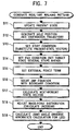
- FIG. 7 is a flowchart showing the flow of processing in the real-time walking-pattern generating unit 25.
- present-state vectors that are to be set as the initial condition of the ZMP equation in the present control cycle are calculated on the basis of the state vectors calculated by the ZMP-equation solving unit 42 in the previous control cycle and the present-state vectors of the robot calculated based on the sensor values (Step S11).
- Step S12 sole position and orientation trajectories several steps ahead are generated in accordance with the present positions and orientations of both the feet and the gait parameters, such as the stride, walking cycle, and turning angle, requested by the user program.
- Step S11 The present-state vectors obtained in Step S11 are set as a start constraint condition of the ZMP equation (Step S13). Similarly, an end constraint condition of the ZMP equation is set on the basis of the sole positions and orientations several steps ahead obtained in Step S12 (Step S14).
- Step S15 The result made by the external-force and external-moment observing unit 23 is set to an external-force term in the ZMP equation (Step S15).
- Step S16 a boundary value problem of the ZMP equation is solved to satisfy these conditions.
- the state of the real world can be reflected in the solution of the ZMP equation, for example, the present-state vectors of the actual robot including the sensor values can be set as the initial condition, and the actually measured external force is reflected in the force term.
- the state vectors (target state vectors) of the robot in the next control cycle are calculated from a solution to the ZMP equation thus obtained (Step S17). These state vectors provide values that permit a smooth transition to the present motion state, that reflect the gait parameters required by the user, and that maintain a dynamic balance under the condition that an external force acts.
- Step S18 the distribution of the mass points in the whole body for realizing the state vectors (target state vectors) is found (Step S18), the result is converted into reference joint angles (Step S19), and a calculation for generating a real-time walking pattern in one control cycle is then completed.
- the state of the real environment is reflected in the real-time walking-pattern generating unit 25. Therefore, there is no need to add a new dynamic model, particularly for the adaptive control system, in order to realize the walking performance adapted to unknown environmental conditions. That is, after the general-purpose real-time walking-pattern generating unit 25 is constructed, it is only necessary to make the robot-state observing unit 21, the environmental-shape observing unit 22, and the external-force and external-moment observing unit 23 for adaptive control functions.
- the robot-state observing unit 21 measures the physical amount corresponding to the state vectors in the real-time walking-pattern generating unit 25 according to values from various sensors. In this embodiment, the position and speed of the center of gravity corresponding to the above-described state vectors in the real-time walking-pattern generating unit 25 are measured.
- FIG. 8 shows a state in which a deviation of the position of the center of gravity is caused by the turning of the entire robot body.
- ⁇ R represents the matrix indicating the inclination deviation obtained by the acceleration sensors and the gyroscopes mounted on the body.
- ⁇ represents the deviation vector obtained of angular velocity obtained from the gyroscopes mounted on the body.
- FIG. 9 is a flowchart showing the procedure for calculating the deviations of the position and speed of the center of gravity in the robot-state observing unit 21 that measures the position and speed of the center of gravity.
- a deviation of the position of the center of gravity is calculated by using Expression 24 above (Step S23), a deviation of the speed of the center of gravity is calculated by using Expression 25 (Step S24), and this processing is then completed.
- the deviation of the position of the center of gravity and the deviation of the speed of the center of gravity thus obtained are input to the present-state determining unit 45.
- acceleration sensors or the gyroscope mounted on the body is simply used as the means for measuring the state vectors in this embodiment, the scope of the present invention is not limited thereto.
- measurement may be made by cooperatively using force sensors, acceleration sensors (e.g., A2 and A3 in FIG. 1), and gyroscopes (e.g., G2 and G3 in FIG. 1) provided at the soles, or acceleration sensors, gyroscopes, and force sensors distributed over the whole body.
- the environmental-shape observing unit 22 calculates the environmental shapes, such as the road irregularities and road inclination, on the basis of values from various sensors, and inputs the environmental shapes to the real-time walking-pattern generating unit 25.
- the environmental shapes such as the road irregularities and road inclination
- the real-time walking-pattern generating unit 25 inputs the environmental shapes to the real-time walking-pattern generating unit 25.
- FIG. 10 illustrates a method for calculating the road inclination.
- the estimated road inclination is increased or decreased by the values corresponding to the products of the load differences between the front and rear sides and between the right and left sides, and a fixed gain, as shown in the following expressions:
- the road inclination is estimated when one of F L and F R in the rolling direction, and one of F F and F B in the pitching direction takes a small value. That is, the estimated road inclination is updated, as needed, until the sole follows the road surface, and the sole is driven to follow the road surface. In contrast, in a state in which the sole has followed the road surface, the estimated road inclination is not updated imprudently. From the above, the road inclination can be properly measured with the sole force sensors.
- the road surface height can be measured with the sole force sensors.
- the estimated road surface height is designated as z F
- the total vertical reactive force detected by the sensors mounted at a target sole is designated as F.
- the estimated road height is gradually increased to adjust the sole trajectory upward, as follows:
- ⁇ z is a small variable.
- the estimated road inclinations ⁇ F and ⁇ F and the estimated road height Z F are measured for each of the right and left soles, and are reflected, in each control cycle, in the positions and orientations of the soles achieved when the soles leave and touch the road surface, in the sole-trajectory generating unit of the real-time walking-pattern generating unit. Consequently, the robot can maintain and continue a stable walking while maintaining a dynamic balance and reconfiguring the sole trajectory to conform to the unknown road surface shape. In particular, a robust walking performance can'be achieved by also using the robot-state observing unit 21.
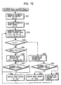
- FIG. 12 is a flowchart showing the procedure for estimating the road inclination and the road surface height. For the sake of simplicity, processing for only one leg will be described. As for the road inclination, processing only in the rolling direction will be described.
- This processing is carried out in each predetermined control cycle, and the estimated road inclination and the estimated road surface height are updated.
- the estimated road inclination and the estimated road surface height are initialized to planned values in Steps S31 and S32.
- Step S33 a total reactive force F and reactive forces F L and F R acting on the four sides of the sole are measured and calculated. On the basis of the results thereof, it is determined whether the sole is in contact with the road (Step S34).
- Step S35 is performed to judge whether the sole follows the road surface.
- Step S36 is then performed.
- Step S37 is performed.
- Step S36 when both the floor reactive forces F L and F R are larger than ⁇ , and it is determined that the sole completely follows the road surface, there is no need to update the estimated road inclination in Step S36, and Step S37 is then performed.
- Step S37 it is determined whether the present time is included in a phase in which the target sole functions as a support leg, in the planned walking pattern.
- the sole touches the road, as planned, and an operation for estimating the road surface shape in one control cycle is completed.
- the sole touches the road surface higher than or equal to the planned value and the estimated road height is updated according to Expression 27 above in Step S38, so that an operation for estimating the road surface shape in one control cycle is completed.
- Step S34 When it is determined in Step S34 that the sole is not in contact with the road surface, computation is performed in Step S39 so that the estimated road inclination gradually returns to the planned value. Subsequently, it is determined whether the present time is included in a phase in which the target sole functions as a support leg in the planned walking pattern (Step S40).
- Step S41 When it is determined that the present time is included in the support leg phase, it is judged that the sole cannot touch the road at a planned timing because the road surface height is lower than the planned value, and the estimated road surface height is updated according to Expression 28 above (Step S41), so that an operation for estimating the road surface shape in one control cycle is completed.
- Step S40 when it is determined in Step S40 that the present time is included in the swing phase, it is considered that the a non-touch state is maintained, as planned.
- Step S42 After computation is performed so that the estimated road surface height gradually returns to the planned value (Step S42), an operation for estimating the road surface shape in one control cycle is completed.
- the environmental shapes are estimated with the sole force sensors serving as the environmental-shape measuring means after the sole touches the road in this embodiment, they may be measured (in a non-contact manner) with ranging sensors (e.g., D1 to D8 in FIG. 1) provided at the sole during the swing phase, or may be measured using a visual function. Alternatively, these functions may be used cooperatively.
- ranging sensors e.g., D1 to D8 in FIG. 1
- the external-force and external-moment observing unit 23 measures the moment acting around the point p on the floor by using a force sensor for one direction perpendicular to the sole.
- a force sensor for one direction perpendicular to the sole.
- the output external moment n is 0.
- the detected external moment is not 0, it can be considered as an unplanned external moment acting on the robot.
- FIG. 13 shows a state in which the moment acting around the point p on the floor is measured with force sensors for one direction perpendicular to the sole.
- FIG. 14 is a flowchart showing the procedure for measuring the moment acting around the point p on the floor with the one-axis force sensors for one direction perpendicular to the sole.
- the present ZMP position p is obtained by the real-time walking-pattern generating unit 25 (Step S53).
- the motion of the whole body can be reconfigured more adaptively to the external moment and the robot can more stably walk, than in the first embodiment.
- the joint angles in the whole body are output which immediately respond to the motion change request from the user and which enable robust walking to be continued in known and unknown environments.
- a desired motion state can be realized by controlling the positions of the joints with, for example, a PID controller in the whole-body joint driving unit with reference to the joint angles in the whole body.
- the scope of the present invention is not limited thereto.
- a ZMP equation that is stated in consideration of the mass of each link, the center of gravity, and the moment of inertia, or an equation of motion, other than the ZMP equation, regarding the whole body of a general type of robot that can express general road surfaces and a non-contact state with the road state may be used.
- the scope of the present invention is not necessarily limited to products called "robots”. That is, the present invention is similarly applicable to any mechanical apparatus that makes motions similar to those of a human being by using an electrical or magnetic effect, even when the apparatus is a product, such as a toy, belonging to a different industrial field.
- the present invention can provide a superior robot apparatus that can properly generate a walking pattern in an actual apparatus and in real time, and a control method for the robot apparatus.
- the present invention can further provide a superior robot apparatus that can properly control the walking while ensuring the consistency of dynamic models for generating the walking pattern and various adaptive control operations, and a control method for the robot apparatus.
- the present invention can further provide a superior robot apparatus that can properly control the stabilization of the body in an embedded CPU having limited calculation resources, and a control method for the robot apparatus.
- the present invention can further provide a superior robot apparatus that can enhance the walking performance by sharing a consistent dynamic model provided in consideration of the mutual interference between adaptive control functions, and a control method for the robot apparatus.
- the locomotion can be continuously changed at desired timings, and a flexible and diversified walking performance can be achieved by the "real-time walking-pattern generating" function for immediately reconfiguring the motion of the whole body while maintaining a dynamic balance of the body so as to satisfy the gait parameters, such as the stride, walking cycle, turning angle, and lifting height of the leg, asynchronously input from sensors and so on.
- the motion of the whole body is reconfigured by the real-time walking-pattern generating function so that the motions of specific portions (e.g., upper limbs) can be performed in combination at a desired timing. Therefore, the specific portions can be asynchronously and reactively driven without imposing a heavy load on the stabilization control system, and the motion pattern can be diversified.
- calculation for a stabilizing algorithm is integrated and united to the calculation in one real-time walking-pattern generating algorithm. Therefore, both the real-time walking-pattern generating function and the stabilizing function can be achieved with high calculation efficiency. This is advantageous in calculation in an embedded CPU having limited calculation resources, and can save the CPU resources.
- a dynamic calculation used in the stabilizing function is integrated into the real-time walking-pattern generating calculation, and the stabilizing function is basically added only by performing an additive input to the setting items in the real-time walking-pattern generating unit. Consequently, it is possible to save the calculations and to construct a highly expandable walking system.
- a dynamic calculation used in the stabilizing function is integrated into one real-time walking-pattern generating calculation made in consideration of the interference effect of various stabilizing operations. Therefore, an undesired interference is not caused between independent dynamic models, a consistent dynamic model is ensured, and a superior locomotion control function can be achieved.
Landscapes
- Engineering & Computer Science (AREA)
- Chemical & Material Sciences (AREA)
- Combustion & Propulsion (AREA)
- Transportation (AREA)
- Mechanical Engineering (AREA)
- Manipulator (AREA)
Applications Claiming Priority (3)
| Application Number | Priority Date | Filing Date | Title |
|---|---|---|---|
| JP2002288745 | 2002-10-01 | ||
| JP2002288745 | 2002-10-01 | ||
| PCT/JP2003/012474 WO2004030870A1 (ja) | 2002-10-01 | 2003-09-30 | ロボット装置及びロボット装置の制御方法 |
Publications (2)
| Publication Number | Publication Date |
|---|---|
| EP1547732A1 true EP1547732A1 (de) | 2005-06-29 |
| EP1547732A4 EP1547732A4 (de) | 2012-01-04 |
Family
ID=32063690
Family Applications (1)
| Application Number | Title | Priority Date | Filing Date |
|---|---|---|---|
| EP03799175A Withdrawn EP1547732A4 (de) | 2002-10-01 | 2003-09-30 | Robotervorrichtung und steuerverfahren dafür |
Country Status (3)
| Country | Link |
|---|---|
| US (1) | US7805218B2 (de) |
| EP (1) | EP1547732A4 (de) |
| WO (1) | WO2004030870A1 (de) |
Families Citing this family (45)
| Publication number | Priority date | Publication date | Assignee | Title |
|---|---|---|---|---|
| US8260593B2 (en) * | 2002-09-18 | 2012-09-04 | Siemens Product Lifecycle Management Software Inc. | System and method for simulating human movement |
| US20050278157A1 (en) * | 2004-06-15 | 2005-12-15 | Electronic Data Systems Corporation | System and method for simulating human movement using profile paths |
| US9129077B2 (en) * | 2004-09-03 | 2015-09-08 | Siemen Product Lifecycle Management Software Inc. | System and method for predicting human posture using a rules-based sequential approach |
| JP4548135B2 (ja) * | 2005-02-03 | 2010-09-22 | トヨタ自動車株式会社 | 脚式ロボットとその制御方法 |
| US8467904B2 (en) * | 2005-12-22 | 2013-06-18 | Honda Motor Co., Ltd. | Reconstruction, retargetting, tracking, and estimation of pose of articulated systems |
| US7859540B2 (en) | 2005-12-22 | 2010-12-28 | Honda Motor Co., Ltd. | Reconstruction, retargetting, tracking, and estimation of motion for articulated systems |
| JP5034235B2 (ja) * | 2006-01-16 | 2012-09-26 | ソニー株式会社 | 制御システム及び制御方法、並びにコンピュータ・プログラム |
| US7719222B2 (en) * | 2006-03-30 | 2010-05-18 | Vecna Technologies, Inc. | Mobile extraction-assist robot |
| US8924021B2 (en) * | 2006-04-27 | 2014-12-30 | Honda Motor Co., Ltd. | Control of robots from human motion descriptors |
| JP4591419B2 (ja) * | 2006-07-18 | 2010-12-01 | トヨタ自動車株式会社 | ロボットとその制御方法 |
| JP5319056B2 (ja) * | 2006-08-01 | 2013-10-16 | トヨタ自動車株式会社 | 燃料電池システム |
| JP4392037B2 (ja) * | 2007-09-12 | 2009-12-24 | トヨタ自動車株式会社 | 脚式ロボット、及びその制御方法 |
| JP4440956B2 (ja) * | 2007-09-12 | 2010-03-24 | トヨタ自動車株式会社 | 脚式ロボット、及びその制御方法 |
| JP5109573B2 (ja) * | 2007-10-19 | 2012-12-26 | ソニー株式会社 | 制御システム及び制御方法、並びにロボット装置 |
| KR101493385B1 (ko) * | 2009-01-09 | 2015-02-13 | 삼성전자 주식회사 | 로봇 및 그 보행 제어장치 및 그 보행 제어방법 |
| JP5506618B2 (ja) * | 2009-12-28 | 2014-05-28 | 本田技研工業株式会社 | ロボットの制御装置 |
| JP5506617B2 (ja) * | 2009-12-28 | 2014-05-28 | 本田技研工業株式会社 | ロボットの制御装置 |
| KR101200191B1 (ko) * | 2010-07-14 | 2012-11-13 | 서울대학교산학협력단 | 데이터 기반 바이페드 제어 장치 및 방법 |
| JP2012171088A (ja) * | 2011-02-24 | 2012-09-10 | Olympus Corp | マスタ操作入力装置及びマスタスレーブマニピュレータ |
| US8504208B2 (en) * | 2011-05-25 | 2013-08-06 | Honda Motor Co., Ltd. | Mobile object controller and floor surface estimator |
| JP5982767B2 (ja) * | 2011-09-26 | 2016-08-31 | ソニー株式会社 | 運動補助装置及び運動補助方法、コンピューター・プログラム、並びにプログラム記録媒体 |
| KR101262978B1 (ko) * | 2011-12-05 | 2013-05-08 | 현대자동차주식회사 | 보행로봇의 반발력 측정 모듈 및 방법 |
| KR101985790B1 (ko) * | 2012-02-21 | 2019-06-04 | 삼성전자주식회사 | 보행 로봇 및 그 제어 방법 |
| US9156159B2 (en) * | 2012-03-08 | 2015-10-13 | Disney Enterprises Inc. | Robot cyclic locomotion using a dynamic object |
| US9041336B2 (en) * | 2012-11-19 | 2015-05-26 | Persimmon Technologies, Corp. | Robot having repeatable disturbance compensation algorithm |
| KR102026382B1 (ko) * | 2014-03-31 | 2019-09-30 | 한국전자통신연구원 | 모션 추정 시스템 및 방법 |
| DE102015205369B4 (de) * | 2014-04-04 | 2019-08-22 | Ford Global Technologies, Llc | Verfahren zum Betrieb eines Federungssystems |
| KR20160017916A (ko) * | 2014-08-07 | 2016-02-17 | 한국전자통신연구원 | 가상 훈련 시뮬레이션 제어 장치 및 그 방법 |
| US9517561B2 (en) * | 2014-08-25 | 2016-12-13 | Google Inc. | Natural pitch and roll |
| US9387588B1 (en) | 2014-08-25 | 2016-07-12 | Google Inc. | Handling gait disturbances with asynchronous timing |
| US9618937B1 (en) | 2014-08-25 | 2017-04-11 | Google Inc. | Slip detection using robotic limbs |
| US9895804B1 (en) * | 2014-08-26 | 2018-02-20 | Boston Dynamics, Inc. | Failure mode |
| JP6228097B2 (ja) * | 2014-10-06 | 2017-11-08 | 本田技研工業株式会社 | 移動ロボット |
| US9499218B1 (en) | 2014-12-30 | 2016-11-22 | Google Inc. | Mechanically-timed footsteps for a robotic device |
| FR3034660B1 (fr) * | 2015-04-07 | 2022-06-10 | Wandercraft | Exosquelette comprenant une liaison mecanique de cheville avec deux axes de pivotement |
| JP6450279B2 (ja) * | 2015-08-05 | 2019-01-09 | 本田技研工業株式会社 | 移動ロボットの目標zmp軌道の生成装置 |
| CN106597843B (zh) * | 2015-10-20 | 2019-08-09 | 沈阳新松机器人自动化股份有限公司 | 一种前驱动轮式机器人安全控制方法及系统 |
| US9925667B1 (en) | 2016-01-25 | 2018-03-27 | Boston Dynamics, Inc. | Continuous slip recovery |
| WO2018035320A1 (en) * | 2016-08-18 | 2018-02-22 | The Trustees Of The University Of Pennsylvania | Systems and methods for controlling robotic behaviors |
| EP3526119B1 (de) * | 2016-10-13 | 2021-12-01 | Alexander Poltorak | Vorrichtung und verfahren zum ausbalancieren eines flugzeugs mit robotischen armen |
| JP6927727B2 (ja) * | 2017-03-29 | 2021-09-01 | 本田技研工業株式会社 | ロボットの制御装置 |
| US10807246B2 (en) * | 2018-01-08 | 2020-10-20 | Beijing Jingdong Shangke Information Technology Co., Ltd. | Mobile robotic device and method of controlling the same manipulator for locomotion and manipulation |
| US11550335B2 (en) * | 2018-11-28 | 2023-01-10 | Ubtech Robotics Corp Ltd | Biped robot and its moving method and apparatus |
| CN111924020B (zh) * | 2020-08-11 | 2022-07-12 | 腾讯科技(深圳)有限公司 | 用于机器人的腿部组件及设备 |
| CN119024853A (zh) * | 2024-08-29 | 2024-11-26 | 广州汽车集团股份有限公司 | 智能移动终端的控制方法、控制系统及智能移动终端 |
Family Cites Families (28)
| Publication number | Priority date | Publication date | Assignee | Title |
|---|---|---|---|---|
| US4975856A (en) * | 1986-02-18 | 1990-12-04 | Robotics Research Corporation | Motion controller for redundant or nonredundant linkages |
| US4860215A (en) * | 1987-04-06 | 1989-08-22 | California Institute Of Technology | Method and apparatus for adaptive force and position control of manipulators |
| US4974210A (en) * | 1989-05-01 | 1990-11-27 | General Electric Company | Multiple arm robot with force control and inter-arm position accommodation |
| US4999553A (en) * | 1989-12-28 | 1991-03-12 | The United States Of America As Represented By The Administrator Of The National Aeronautics And Space Administration | Method and apparatus for configuration control of redundant robots |
| US5483630A (en) * | 1990-07-12 | 1996-01-09 | Hitachi, Ltd. | Method and apparatus for representing motion of multiple-jointed object, computer graphic apparatus, and robot controller |
| US5179514A (en) * | 1990-08-08 | 1993-01-12 | The Research Foundation Of State University Of New York | Method and apparatus for trajectory control of robot manipulators or the like |
| US5444612A (en) * | 1991-04-16 | 1995-08-22 | Fanuc Ltd. | Adaptive PI control system |
| US5355064A (en) * | 1992-03-04 | 1994-10-11 | Honda Giken Kogyo Kabushiki Kaisha | Control system for legged mobile robot |
| US5349277A (en) * | 1992-03-12 | 1994-09-20 | Honda Giken Kogyo Kabushiki Kaisha | Control system for legged mobile robot |
| US5432417A (en) * | 1992-04-30 | 1995-07-11 | Honda Giken Kogyo Kabushiki Kaisha | Locomotion control system for legged mobile robot |
| US5294873A (en) * | 1992-10-27 | 1994-03-15 | The United States Of America As Represented By The Administrator Of The National Aeronautics And Space Administration | Kinematic functions for redundancy resolution using configuration control |
| JPH06314103A (ja) * | 1993-04-30 | 1994-11-08 | Fujitsu Ltd | 制御装置と能動的センシング装置 |
| JP3436320B2 (ja) * | 1994-04-18 | 2003-08-11 | 富士通株式会社 | 非線形システムの出力軌道と動特性の制御方法および装置 |
| US5594309A (en) * | 1994-06-15 | 1997-01-14 | Iowa State University Research Foundation, Inc. | Robot control scheme |
| US5808433A (en) * | 1995-09-29 | 1998-09-15 | Honda Giken Kogyo Kabushiki Kaisha | Method of generating gait of legged walking robot and system for controlling its locomotion |
| JP3662996B2 (ja) * | 1996-01-25 | 2005-06-22 | 本田技研工業株式会社 | 脚式移動ロボットの歩行制御装置 |
| US5872893A (en) * | 1996-07-25 | 1999-02-16 | Honda Giken Kogyo Kabushiki Kaisha | Gait generation system of legged mobile robot |
| US6505096B2 (en) * | 1996-12-19 | 2003-01-07 | Honda Giken Kogyo Kabushiki Kaisha | Posture control system of legged mobile robot |
| JP3672406B2 (ja) | 1997-01-31 | 2005-07-20 | 本田技研工業株式会社 | 脚式移動ロボットの歩容生成装置 |
| EP1053835B1 (de) * | 1997-01-31 | 2006-12-27 | Honda Giken Kogyo Kabushiki Kaisha | Steuergerät eines mit beinen beweglichen roboters |
| US6064168A (en) * | 1998-03-13 | 2000-05-16 | Fanuc Robotics North America, Inc. | Method of controlling robot movement |
| US6289265B1 (en) * | 1998-04-20 | 2001-09-11 | Honda Giken Kogyo Kabushiki Kaisha | Controller for legged mobile robot |
| JP3124519B2 (ja) * | 1998-07-23 | 2001-01-15 | セイコー精機株式会社 | 制御系のモード切替え機能を有するロボット制御装置 |
| JP2001191284A (ja) * | 1999-10-25 | 2001-07-17 | Sony Corp | ロボット装置及びロボット装置の学習方法 |
| JP3615702B2 (ja) * | 1999-11-25 | 2005-02-02 | ソニー株式会社 | 脚式移動ロボットの動作制御装置及び動作制御方法、並びに、脚式移動ロボット |
| JP2001150374A (ja) * | 1999-11-25 | 2001-06-05 | Sony Corp | ロボットの故障診断システム |
| JP2001322079A (ja) * | 2000-05-15 | 2001-11-20 | Sony Corp | 脚式移動ロボット及びその動作教示方法 |
| US7158840B2 (en) * | 2001-06-29 | 2007-01-02 | Cymer, Inc. | Tuning control parameters of vibration reduction and motion control systems for fabrication equipment and robotic systems |
-
2003
- 2003-09-30 WO PCT/JP2003/012474 patent/WO2004030870A1/ja not_active Ceased
- 2003-09-30 US US10/497,096 patent/US7805218B2/en not_active Expired - Fee Related
- 2003-09-30 EP EP03799175A patent/EP1547732A4/de not_active Withdrawn
Also Published As
| Publication number | Publication date |
|---|---|
| WO2004030870A1 (ja) | 2004-04-15 |
| EP1547732A4 (de) | 2012-01-04 |
| US20050107916A1 (en) | 2005-05-19 |
| US7805218B2 (en) | 2010-09-28 |
Similar Documents
| Publication | Publication Date | Title |
|---|---|---|
| US7805218B2 (en) | Robot device and control method of robot device | |
| JP3599244B2 (ja) | ロボット装置、ロボット装置の運動制御装置並びに運動制御方法 | |
| US7053577B2 (en) | Robot and motion control method of robot | |
| US7386364B2 (en) | Operation control device for leg-type mobile robot and operation control method, and robot device | |
| JP5284923B2 (ja) | 脚式移動ロボットの制御装置 | |
| JP5456588B2 (ja) | 脚式移動ロボットの制御装置 | |
| JP5483997B2 (ja) | 脚式移動ロボットの制御装置 | |
| KR100937268B1 (ko) | 다리식 이동 로봇 및 그 동작 제어 방법 | |
| KR100837988B1 (ko) | 각식 이동 로봇을 위한 동작 제어 장치 및 동작 제어방법, 및 로봇 장치 | |
| US20040254679A1 (en) | Robot movement control system | |
| JP4483254B2 (ja) | ロボット装置及びロボット装置の制御方法 | |
| KR20010050543A (ko) | 로봇의 이동 제어 장치 및 이동 제어 방법 | |
| KR20230120651A (ko) | 외골격 움직임 방법 | |
| CN119734255A (zh) | 一种冗余自由度约束的类人机器人预测控制方法及机器人 | |
| JP6407409B2 (ja) | 脚型機構体、歩行ロボット、姿勢制御方法及びプログラム | |
| JP3674779B2 (ja) | 脚式移動ロボットのための動作制御装置及び動作制御方法、並びにロボット装置 | |
| JP5232120B2 (ja) | 移動体の制御装置 | |
| Sari et al. | Implementation and integration of fuzzy algorithms for descending stair of KMEI humanoid robot | |
| CN120439281A (zh) | 一种针对12自由度的双足人形机器人步态控制方法 | |
| JP2003159676A (ja) | 脚式移動ロボットの制御方法 |
Legal Events
| Date | Code | Title | Description |
|---|---|---|---|
| PUAI | Public reference made under article 153(3) epc to a published international application that has entered the european phase |
Free format text: ORIGINAL CODE: 0009012 |
|
| 17P | Request for examination filed |
Effective date: 20040528 |
|
| AK | Designated contracting states |
Kind code of ref document: A1 Designated state(s): AT BE BG CH CY CZ DE DK EE ES FI FR GB GR HU IE IT LI LU MC NL PT RO SE SI SK TR |
|
| RBV | Designated contracting states (corrected) |
Designated state(s): DE FR GB |
|
| A4 | Supplementary search report drawn up and despatched |
Effective date: 20111205 |
|
| RIC1 | Information provided on ipc code assigned before grant |
Ipc: B25J 5/00 20060101AFI20111129BHEP |
|
| GRAC | Information related to communication of intention to grant a patent modified |
Free format text: ORIGINAL CODE: EPIDOSCIGR1 |
|
| GRAP | Despatch of communication of intention to grant a patent |
Free format text: ORIGINAL CODE: EPIDOSNIGR1 |
|
| STAA | Information on the status of an ep patent application or granted ep patent |
Free format text: STATUS: THE APPLICATION IS DEEMED TO BE WITHDRAWN |
|
| 18D | Application deemed to be withdrawn |
Effective date: 20130403 |