EP1547725B1 - Werkzeugaufnahmetopf - Google Patents
Werkzeugaufnahmetopf Download PDFInfo
- Publication number
- EP1547725B1 EP1547725B1 EP04027296A EP04027296A EP1547725B1 EP 1547725 B1 EP1547725 B1 EP 1547725B1 EP 04027296 A EP04027296 A EP 04027296A EP 04027296 A EP04027296 A EP 04027296A EP 1547725 B1 EP1547725 B1 EP 1547725B1
- Authority
- EP
- European Patent Office
- Prior art keywords
- wall
- wall structure
- tool
- tool pot
- pot
- Prior art date
- Legal status (The legal status is an assumption and is not a legal conclusion. Google has not performed a legal analysis and makes no representation as to the accuracy of the status listed.)
- Ceased
Links
- 239000012763 reinforcing filler Substances 0.000 claims description 25
- 239000000463 material Substances 0.000 claims description 17
- 230000002787 reinforcement Effects 0.000 claims description 4
- 239000000057 synthetic resin Substances 0.000 claims description 4
- 229920003002 synthetic resin Polymers 0.000 claims description 4
- 229920005992 thermoplastic resin Polymers 0.000 claims description 4
- 239000011347 resin Substances 0.000 description 15
- 229920005989 resin Polymers 0.000 description 15
- 101100298222 Caenorhabditis elegans pot-1 gene Proteins 0.000 description 14
- 229920001169 thermoplastic Polymers 0.000 description 13
- 239000004416 thermosoftening plastic Substances 0.000 description 13
- 238000010276 construction Methods 0.000 description 10
- 239000003365 glass fiber Substances 0.000 description 9
- 239000004952 Polyamide Substances 0.000 description 7
- 229920002647 polyamide Polymers 0.000 description 7
- VTYYLEPIZMXCLO-UHFFFAOYSA-L Calcium carbonate Chemical compound [Ca+2].[O-]C([O-])=O VTYYLEPIZMXCLO-UHFFFAOYSA-L 0.000 description 4
- 229920002302 Nylon 6,6 Polymers 0.000 description 4
- 229920000122 acrylonitrile butadiene styrene Polymers 0.000 description 4
- 239000010410 layer Substances 0.000 description 4
- 230000003014 reinforcing effect Effects 0.000 description 4
- 238000004519 manufacturing process Methods 0.000 description 3
- 238000004064 recycling Methods 0.000 description 3
- 229920000049 Carbon (fiber) Polymers 0.000 description 2
- 229930182556 Polyacetal Natural products 0.000 description 2
- 239000004793 Polystyrene Substances 0.000 description 2
- 229910000019 calcium carbonate Inorganic materials 0.000 description 2
- 239000004917 carbon fiber Substances 0.000 description 2
- 238000002347 injection Methods 0.000 description 2
- 239000007924 injection Substances 0.000 description 2
- 238000002372 labelling Methods 0.000 description 2
- 230000008018 melting Effects 0.000 description 2
- 238000002844 melting Methods 0.000 description 2
- 229910052751 metal Inorganic materials 0.000 description 2
- 239000002184 metal Substances 0.000 description 2
- VNWKTOKETHGBQD-UHFFFAOYSA-N methane Chemical compound C VNWKTOKETHGBQD-UHFFFAOYSA-N 0.000 description 2
- 239000010445 mica Substances 0.000 description 2
- 229910052618 mica group Inorganic materials 0.000 description 2
- 239000000203 mixture Substances 0.000 description 2
- 229920000515 polycarbonate Polymers 0.000 description 2
- 239000004417 polycarbonate Substances 0.000 description 2
- 229920006324 polyoxymethylene Polymers 0.000 description 2
- 229920002223 polystyrene Polymers 0.000 description 2
- 239000002356 single layer Substances 0.000 description 2
- 239000012815 thermoplastic material Substances 0.000 description 2
- 239000013585 weight reducing agent Substances 0.000 description 2
- KXGFMDJXCMQABM-UHFFFAOYSA-N 2-methoxy-6-methylphenol Chemical compound [CH]OC1=CC=CC([CH])=C1O KXGFMDJXCMQABM-UHFFFAOYSA-N 0.000 description 1
- 239000000853 adhesive Substances 0.000 description 1
- 230000001070 adhesive effect Effects 0.000 description 1
- 230000002708 enhancing effect Effects 0.000 description 1
- 230000014759 maintenance of location Effects 0.000 description 1
- 230000004048 modification Effects 0.000 description 1
- 238000012986 modification Methods 0.000 description 1
- 238000000465 moulding Methods 0.000 description 1
- 229920001568 phenolic resin Polymers 0.000 description 1
- 239000005011 phenolic resin Substances 0.000 description 1
- 125000006850 spacer group Chemical group 0.000 description 1
- 238000003466 welding Methods 0.000 description 1
- 230000003245 working effect Effects 0.000 description 1
Images


Classifications
-
- B—PERFORMING OPERATIONS; TRANSPORTING
- B23—MACHINE TOOLS; METAL-WORKING NOT OTHERWISE PROVIDED FOR
- B23Q—DETAILS, COMPONENTS, OR ACCESSORIES FOR MACHINE TOOLS, e.g. ARRANGEMENTS FOR COPYING OR CONTROLLING; MACHINE TOOLS IN GENERAL CHARACTERISED BY THE CONSTRUCTION OF PARTICULAR DETAILS OR COMPONENTS; COMBINATIONS OR ASSOCIATIONS OF METAL-WORKING MACHINES, NOT DIRECTED TO A PARTICULAR RESULT
- B23Q3/00—Devices holding, supporting, or positioning work or tools, of a kind normally removable from the machine
- B23Q3/155—Arrangements for automatic insertion or removal of tools, e.g. combined with manual handling
- B23Q3/157—Arrangements for automatic insertion or removal of tools, e.g. combined with manual handling of rotary tools
- B23Q3/15713—Arrangements for automatic insertion or removal of tools, e.g. combined with manual handling of rotary tools a transfer device taking a single tool from a storage device and inserting it in a spindle
- B23Q3/1572—Arrangements for automatic insertion or removal of tools, e.g. combined with manual handling of rotary tools a transfer device taking a single tool from a storage device and inserting it in a spindle the storage device comprising rotating or circulating storing means
- B23Q3/15724—Chains or belts
-
- B—PERFORMING OPERATIONS; TRANSPORTING
- B23—MACHINE TOOLS; METAL-WORKING NOT OTHERWISE PROVIDED FOR
- B23Q—DETAILS, COMPONENTS, OR ACCESSORIES FOR MACHINE TOOLS, e.g. ARRANGEMENTS FOR COPYING OR CONTROLLING; MACHINE TOOLS IN GENERAL CHARACTERISED BY THE CONSTRUCTION OF PARTICULAR DETAILS OR COMPONENTS; COMBINATIONS OR ASSOCIATIONS OF METAL-WORKING MACHINES, NOT DIRECTED TO A PARTICULAR RESULT
- B23Q3/00—Devices holding, supporting, or positioning work or tools, of a kind normally removable from the machine
- B23Q3/155—Arrangements for automatic insertion or removal of tools, e.g. combined with manual handling
- B23Q3/1552—Arrangements for automatic insertion or removal of tools, e.g. combined with manual handling parts of devices for automatically inserting or removing tools
- B23Q3/15553—Tensioning devices or tool holders, e.g. grippers
-
- B—PERFORMING OPERATIONS; TRANSPORTING
- B23—MACHINE TOOLS; METAL-WORKING NOT OTHERWISE PROVIDED FOR
- B23Q—DETAILS, COMPONENTS, OR ACCESSORIES FOR MACHINE TOOLS, e.g. ARRANGEMENTS FOR COPYING OR CONTROLLING; MACHINE TOOLS IN GENERAL CHARACTERISED BY THE CONSTRUCTION OF PARTICULAR DETAILS OR COMPONENTS; COMBINATIONS OR ASSOCIATIONS OF METAL-WORKING MACHINES, NOT DIRECTED TO A PARTICULAR RESULT
- B23Q3/00—Devices holding, supporting, or positioning work or tools, of a kind normally removable from the machine
- B23Q3/155—Arrangements for automatic insertion or removal of tools, e.g. combined with manual handling
- B23Q3/1552—Arrangements for automatic insertion or removal of tools, e.g. combined with manual handling parts of devices for automatically inserting or removing tools
- B23Q3/15526—Storage devices; Drive mechanisms therefor
- B23Q2003/15532—Storage devices; Drive mechanisms therefor the storage device including tool pots, adaptors or the like
-
- Y—GENERAL TAGGING OF NEW TECHNOLOGICAL DEVELOPMENTS; GENERAL TAGGING OF CROSS-SECTIONAL TECHNOLOGIES SPANNING OVER SEVERAL SECTIONS OF THE IPC; TECHNICAL SUBJECTS COVERED BY FORMER USPC CROSS-REFERENCE ART COLLECTIONS [XRACs] AND DIGESTS
- Y10—TECHNICAL SUBJECTS COVERED BY FORMER USPC
- Y10T—TECHNICAL SUBJECTS COVERED BY FORMER US CLASSIFICATION
- Y10T483/00—Tool changing
- Y10T483/18—Tool transfer to or from matrix
- Y10T483/1809—Matrix including means to latch tool
-
- Y—GENERAL TAGGING OF NEW TECHNOLOGICAL DEVELOPMENTS; GENERAL TAGGING OF CROSS-SECTIONAL TECHNOLOGIES SPANNING OVER SEVERAL SECTIONS OF THE IPC; TECHNICAL SUBJECTS COVERED BY FORMER USPC CROSS-REFERENCE ART COLLECTIONS [XRACs] AND DIGESTS
- Y10—TECHNICAL SUBJECTS COVERED BY FORMER USPC
- Y10T—TECHNICAL SUBJECTS COVERED BY FORMER US CLASSIFICATION
- Y10T483/00—Tool changing
- Y10T483/18—Tool transfer to or from matrix
- Y10T483/1864—Tool transfer to or from matrix including tool pot or adapter
-
- Y—GENERAL TAGGING OF NEW TECHNOLOGICAL DEVELOPMENTS; GENERAL TAGGING OF CROSS-SECTIONAL TECHNOLOGIES SPANNING OVER SEVERAL SECTIONS OF THE IPC; TECHNICAL SUBJECTS COVERED BY FORMER USPC CROSS-REFERENCE ART COLLECTIONS [XRACs] AND DIGESTS
- Y10—TECHNICAL SUBJECTS COVERED BY FORMER USPC
- Y10T—TECHNICAL SUBJECTS COVERED BY FORMER US CLASSIFICATION
- Y10T483/00—Tool changing
- Y10T483/18—Tool transfer to or from matrix
- Y10T483/1873—Indexing matrix
- Y10T483/1891—Chain or belt
Definitions
- the present invention relates to a tool pot used for a tool magazine of a machine tool, and more particularly, to a tool,pot made from synthetic resin, whose circumferential wall has a two-layer construction of an inner wall structure located at least toward an opening end of an attachment hole and in inner side, and an outer wall structure located around the inner wall structure.
- Japanese Laid-Open Patent No. 2002-273633 discloses a tool pot made from synthetic resin and having two-layer construction.
- An inner wall of the tool pot is made from heat-hardening resin such as phenolic resin, and an outer wall located around the inner wall is made from thermo-plastic resin such as ABS resin containing reinforcing filler such as glass fiber.
- Japanese Laid-Open Patent No. 2001-347434 discloses a tool pot having a single layer construction that is entirely molded from thermo-plastic resin such as ABS resin containing reinforcing filler such as glass fiber.
- the inner part of a tool attachment hole has rigidity, too. Accordingly, if a tool is dislocated from an exact inserting position when inserted into the attachment hole, the tool is liable to contact the tool pot unexpectedly and be damaged by the tool pot.
- the present invention contemplates to solve the above mentioned problems, and therefore, has an object to provide a tool pot capable of preventing damages to tools, and is recyclable.
- a circumferential wall of a tool attachment hole of the tool pot according to the present invention is made from synthetic resin.
- the circumferential wall includes an inner wall structure located at least toward an opening end of the attachment hole and in inner side, and an outer wall structure located around the inner wall structure.
- the inner wall structure and outer wall structure are made from thermoplastic resin, and the outer wall structure contains more reinforcing filler than the inner wall structure.
- the inner wall structure contains less reinforcing filler than the outer wall structure, and thus has lower rigidity, strength and hardness, the inner wall does not damage tools even if it contacts with the tools.
- the outer wall structure containing more reinforcing filler than the inner wall has increased rigidity, and therefore, is capable of preventing the inner wall from being deformed, and is durable as tool holder.
- both the inner and outer wall structure are made from thermo-plastic resin material, both of them can be melted and recycled.
- the tool pot of the present invention prevents damages to tools, and is recyclable.
- thermoplastic resin material is exemplified by ABS resin, polyacetal, polyamide, polystyrene, or polycarbonate or the like
- reinforcing filler is exemplified by glass fiber, carbon fiber, mica, or calcium carbonate or the like.
- a content of reinforcing filler of the inner wall structure is less than 5 weight %, and a content of reinforcing filler of the outer wall structure is within a range of 5 to 60 weight %.
- thermo-plastic resin materials forming the inner and outer wall structure are easily available as recycled material. Therefore, manufacturing cost of the tool pots can be remarkably reduced to 1/4 to 1/5. Especially, if the content of reinforcing filler of the outer wall structure is in a range of 15 to 60 weight %, the outer wall is light-weight and compact, while keeping sufficient strength, and therefore, practical tool pots are provided.
- the tool pot when the tool pot is recycled, the tool pot is labeled as is wholly made from the same material, which facilitates the labeling of recycling, compared to a case where the inner wall and outer wall are made from different thermo-plastic materials.
- the pots when the pots are heat-treated to be molten, the recycling treatment is facilitated since the whole pot is melted at the same melt-temperature.
- outer wall structure is substantially columnar in outer shape, and includes a plurality of ribs for reinforcement in inner surface thereof.
- the tool pot does not have reinforcing ribs on outer surface of the outer wall, so that an outer side of the outer wall has a substantially columnar shape with smooth face. Accordingly, when tools are exchanged, the tool pot is accurately shifted to match with a center of a positioning face of a positioning device, without hindrance of ribs, by applying the positioning face, which is so arcuate as to correspond to the outer side of the outer wall, to the outer side of the outer wall. Therefore, the tool pot is easily and accurately located in a predetermined stop position utilizing the outer side of the outer wall having a substantially columnar shape.
- the positioning face of the positioning device may vary due to change of location of the positioning device and so on, the positioning face can be applied to the outer side of the outer wall from any circumferential direction of the tool pot, since the outer side of the outer wall has a substantially columnar shape. This facilitates positioning of the tool pot.
- the ribs contribute to weight reduction and reinforcement of the tool pot.
- the reinforcing ribs are desirably arranged along axial direction of the outer wall.
- the ribs are molded easily without utilizing slide core and so on.
- the inner wall structure includes a first tapered inner surface located toward an opening end of the tool attachment hole and so tapered toward the opening end of the attachment hole as to correspond to a shank portion of a tool inserted into the attachment hole, thereby the shank portion abuts against and is supported by the tapered inner surface, and that the outer wall structure includes a second tapered inner surface defining a deeper side of the attachment hole, and the second tapered surface does not abut against the shank portion.
- the inner wall can be arranged to accommodate various tools only by exchanging the inner wall. For example, if a shape of shank portion of a tool to be housed in the tool pot is changed, the inner wall has only to be exchanged while leaving the outer wall as it is. Therefore, the tool pot can handle various kinds of tools with simple exchanging work of the inner wall.
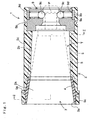
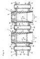
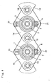
- Figs. 1 and 2 illustrate a tool pot 1 according to a first embodiment of the invention. Numbers of tool pot 1 are held in a chain 11 as a pot retention mechanism of a tool magazine, as shown in Figs. 3 and 4.
- the chain 11 includes pairs of outer plates 12 and inner plates 14 connected with one another by pins 16 sheathed with collars 17.
- the pins 16 and collars 17 help separate the pairs of inner plate 12 and outer plate 14 each of which confronts each other at predetermined clearance.
- Each of the tool pots 1 is located to penetrate the opposing plates 12 or 14, and is held in the chain 11 by a step 5a formed on outer surface of outer wall structure 5 and a holding ring 13 fitted in a groove 5b.
- a spacer 15 helps hold the tool pot 1.
- Each of the pins 16 is fixed between the plates 12 or plates 14 by washers 19 located in both ends, which are held by holding rings 20.
- a member represented by reference numeral 18 is a bushing disposed between the plate 12 or 14 and the pin 16.
- the chain 11 is provided, at both ends of a direction perpendicular to line-up direction of the pins 16 in each of the plates 12/14, with rollers 21 supported by bearings.
- the rollers 21 are engaged with unillustrated driving and driven sprockets of the tool magazine, and drive the chain 11 cyclically by the driving sprockets.
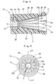
- Each of the tool pots 1 has a tool attachment hole 2 in which shank portion S and pull-stud P of a tool T is inserted.
- a circumferential wall 3 of the attachment hole 2 forms a substantially cylindrical shape, and is provided with a tapered portion 2a tapering toward an opening end 3a according to the shape of a shank portion S of the tool T, and a tapered portion 2b tapering more gradually in deeper side.
- the circumferential wall 3 includes an inner wall structure 4 located in a leading end part of the tool pot 1 and in inner side of the tapered portion 2a, and an outer wall structure 5 located around the inner wall structure 4 and the tapered portion 2b in the deeper side.
- a tool gripping mechanism 9 for holding the tool T by gripping the pull-stud P.
- the shank portion S abuts against an inner surface (tapered portion) 2a in the opening end 3a part, but does not abut against an inner surface (tapered portion) 2b of the outer wall structure 5.
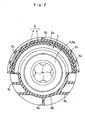
- the tool gripping mechanism 9 includes a metal block 9a and four balls 9c disposed inside the metal block 9a.
- Each of the balls 9c is constructed to move centrally of the attachment hole 2 by coil springs 9d, and the four balls 9c cooperatively grip the inserted pull-stud P of the tool T to hold the tool T with the shank portion S abutted against the inner surface (tapered portion) 2a of the inner wall structure 4.
- a member represented by reference numeral 9 is a holding ring for supporting an end of the coil spring 9d.
- the inner wall structure 4 and outer wall structure 5 of the circumferential wall 3 are both injection molded from thermo-plastic resin.
- the outer wall structure 5 contains more reinforcing filler than the inner wall structure 4.
- the outer wall structure 5 is molded from polyamide (more particularly, Nylon 66) containing 30 weight % of glass fiber as reinforcing filler, while the inner wall structure 4 is molded from polyamide (Nylon 66) containing no reinforcing filler.
- the outer wall structure 5 is provided in outer surface thereof with numbers of ribs 5c for enhancing rigidity.
- a pre-molded inner wall 4 and the tool gripping mechanism 9 are set in a mold for forming the outer wall 5 as inserts, the mold is closed, and then the outer wall structure 5 is injection molded.
- the inner wall structure 4 contains less reinforcing filler than the outer wall structure 5, and thus has lower rigidity, strength and hardness, the inner wall 4 does not damage tools T even if it contacts with the tools T.
- the outer wall structure 5 containing more reinforcing filler than the inner wall 4 has improved rigidity, and therefore, is capable of preventing the inner wall 4 from being deformed, and holding tools T with durability.
- both the inner wall 4 and outer wall 5 are made from thermo-plastic resin material, both of them can be melted and recycled.
- the tool pot 1 of the first embodiment of the invention prevents damages to tools T, and is recyclable.
- content of glass fiber of the inner wall 4 is 0 weight %, which is less than 5 weight %, while content of glass fiber of the outer wall 5 is 30 weight %, which is within a range of 5 to 60 weight %.
- the inner wall 4 and outer wall 5 are made from the same thermo-plastic resin material, or polyamide. Accordingly, when the tool pot 1 is recycled, the tool pot 1 is labeled as is wholly made from the same material, which facilitates the labeling of recycling, compared to a case where the inner wall and outer wall are made from different thermo-plastic materials. In addition, when the pots 1 are heat-treated to be molten, the recycle treatment is facilitated since the whole pot is melted at the same melt-temperature.
- the inner wall 4 and outer wall 5 may be molded from different thermo-plastic resin materials.
- the two materials are easily recycle-treated at the same melt-temperature.
- melting points of two materials may be different.
- thermo-plastic resin material employed in this embodiment should not be limited to polyamide, but ABS resin, polyacetal, polystyrene, or polycarbonate may also be employed.
- the inner wall 4 in the foregoing embodiment contains no reinforcing filler such as glass fiber
- the thermo-plastic resin material for the inner wall 4 may contain less than 5 weight % of reinforcing filler, since damaging to tools T is prevented if the content of reinforcing filler is less than 5 weight %.
- reinforcing filler should not be limited to glass fiber, but carbon fiber, mica, or calcium carbonate may also be employed.
- the outer wall 5 in the foregoing embodiment contains 30 weight % of reinforcing filler, the content has only to be within a range of 5 to 60 weight % (more desirably, 15 to 60 weight %). If it is less than 5 weight %, strength sufficient to prevent deformation of the inner wall 4 is not secured. If the content exceeds 60 weight %, molding of the outer wall 5 is difficult.
- the inner wall structure 4 is arranged only toward the opening end 3a in an inner circumference of the circumferential wall 3, the inner wall structure 4 may be arranged substantially all over the inner circumference of the circumferential wall 3.
- the tool pot 1 in the first embodiment is provided with the ribs 5c on outer surface of the outer wall 5
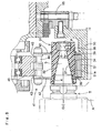
- the tool pot may be provided with ribs in inner surface of the outer wall, as a tool pot 31 of a second embodiment of the present invention shown in Figs. 5 to 9.
- An outer wall structure 32 of the tool pot 31 is located around an inner wall structure 4, which is arranged only toward an opening end 3a of a circumferential wall 3, and also constitutes a deeper side of inner surface of a tool attachment hole 2 than the inner wall structure 4.
- the outer wall structure 32 is substantially columnar in outer shape, and includes in inner surface thereof with a plurality of (12, in the illustrated embodiment) reinforcing ribs 37 arranged in axial direction of the outer wall 32.
- Leading end faces 37b of the ribs 37 provide a tapered portion 2b that is located in deeper side of the attachment hole 2 than a tapered portion 2a provided by the inner wall 4. Meanwhile, end faces of the ribs 37 oriented toward the opening end 3a provide a recess 37a for fixing the inner wall 4 whose inner diameter and outer diameter diverge toward the opening end 3a therein.
- the ribs 37 continue to a substantially cylindrical flange portion 33 arranged around the outer wall 32 near the opening end 3a, and also continue to a cylindrical bottom portion 38 in root side away from the opening end 3a. That is, both axial ends of the ribs 37 are joined with one another in circumferential direction of the outer wall 32.
- the inner wall 4 of the tool pot 31 is made from polyamide (more particularly, Nylon 66) containing no reinforcing filler, while the outer wall 32 is made from polyamide (Nylon 66) containing 30 weight % of glass fiber as reinforcing filler, as in the tool pot 1.
- a tool gripping mechanism 9 is at the bottom of the attachment hole 2 .
- the tool pot 31 is manufactured by joining the separately molded inner wall 4 and the outer wall 32 by adhesive, vibration welding or the like.
- the tool pot 31 holds a tool T by gripping a pull-stud P with balls 9c of the tool gripping mechanism 9, with a shank portion S abutted against and supported by the inner surface 2a of the inner wall 4.
- an outer side 34 of the outer wall 32 has a cylindrical shape except in the flange portion 33 and in a groove 36, thereby having a circular section.
- Center C of the cylindrical outer side 34 is predetermined to conform with a center of the shank portion S of the tool T as housed in the tool pot 31.
- the flange portion 33 has a greater diameter than the outer side 34 by a step 35, and is provided with a flat portion 33a for locating a key 6.
- the groove 36 located in a root part of the outer side 34 helps attach the tool pot 31 to a chain 41 as a pot holding mechanism, together with the step 35. More particularly, the tool pot 31 is attached to the chain 41 by applying the step 35 to one of confronting outer plates 42 of the chain 41 extending from both ends of each of rollers 44 engaged with a sprocket 40, and applying a holding ring 39 fitted in the groove 36 to the other plate 42.
- the chain 41 in the illustrated embodiment includes numbers of pairs of confronting outer plates 42 each connected by two rollers 44 engaged with the sprocket 40 and two tie rods 45, and inner plates 43 joining pairs of outer plates 42 that are adjacent one another in a direction perpendicular to the axis of the roller 44.
- a positioning device 50 below a track of the tool pots 31 transferred by cyclical driving of the chain 41 is a positioning device 50, as shown in Figs. 7 and 8, on which an arm A of a robot takes out a tool T from the tool pot 31 and returns a used tool T.
- the positioning device 50 is linked with a piston rod 55 reciprocating vertically, and a positioning block 51 is fixed above the positioning device 50.
- the positioning block 51 includes a positioning face 51a recessed in quarter arcuate shape corresponding to generally quarter outer shape of the outer side 34 of the outer wall 32 of the tool pot 31.
- Center O of curvature radius of the positioning face 51a as risen to uppermost position is called herein as base position O (refer to Figs. 7, 8 and 9B) for the arm A of the robot to exchange tools T.
- Exchange of tools T is performed with the center C of the tool pot 31, which conforms with a center of the shank portion S of the tool T held by the tool pot 31, matched with the center O.
- the positioning block 51 does not interfere with the tool pots 31 transferred by the chain 41.
- the center C of the tool pot 31 may not conform with the exchange base position O at first.
- the positioning block 51 of the positioning device 50 ascends toward the uppermost position, a part of the outer side 34 of the outer wall 32 in the tool pot 31 contacts with the positioning face 51a firstly, as shown in Fig. 9A, and then the tool pot 31 is guided by the positioning face 51a along with ascent of the positioning face 51a, and matches the center C with the base position O, as shown in Fig. 9B.
- the tool pot 31 is ready for the arm A of the robot to take out a tool T from the tool pot 31 or return a used tool T to the tool pot 31.
- the tool pot 31 does not have reinforcing ribs on outer surface of the outer wall 32, so that the outer side 34 of the outer wall 32 has a substantially columnar shape with smooth face. Accordingly, when tools T are exchanged, the tool pot 31 is accurately shifted to match with the center O of the positioning face 51a without hindrance of ribs by applying the positioning face 51a, which is so arcuate to correspond to the outer side 34 of the outer wall 32, to the tool pot 31. Contrarily, if the outer wall 32 is provided with ribs 5c on outer surface, as in the outer wall 5 of the tool pot 1, it would be difficult to locate a tool pot in a predetermined stop position O since the ribs 5c are likely to get caught by an end portion 51b (refer to Fig. 9A) of the positioning block 51.
- the tool pot 31 of the second embodiment is located in a predetermined stop position O easily and accurately utilizing the smooth outer side 34 of the outer wall 32 having a substantially columnar shape.
- the positioning face 51a of the positioning device 50 of the foregoing embodiment is constructed to be applied to the tool pot 31 from lower side, even if applying direction of the positioning face 51a varies due to change of location of the positioning device 50 and so on, the positioning face 51a can be applied to the outer side 34 of the outer wall 32 from any circumferential direction of the tool pot 31 since the outer side 34 has a substantially columnar shape. This facilitates the positioning of the tool pot 31.
- the ribs 37 contribute to weight reduction and reinforcement of the tool pot 31.
- the tool pot 1/31 in the preferred embodiments has two-layer construction of the inner wall structure 4 having a tapered portion 2a for supporting the shank portion S, and the outer wall structure 5/32 not supporting. the shank portion S directly.
- the inner wall 4 can be arranged to accommodate various tools T only by exchanging the inner wall 4.
- the inner wall 4 may be arranged in entire length of the attachment hole 2 of the tool pot 31.
- the ribs 37 of the outer wall 32 are arranged along axial direction of the outer wall 32, and therefore, the ribs 37 are molded easily without utilizing slide core and so on.
Landscapes
- Engineering & Computer Science (AREA)
- Mechanical Engineering (AREA)
- Automatic Tool Replacement In Machine Tools (AREA)
Claims (7)
- Werkzeugaufnahmetopf (1, 31), wobei eine Umfangswand (3) seines Werkzeuganbringlochs (2) aus synthetischem Harz gebildet ist, dadurch gekennzeichnet, dass:die Umfangswand (3) eine innere Wandstruktur (4), die zumindest in Richtung eines Öffnungsendes (3a) des Befestigungslochs (2) und in einer inneren Seite positioniert ist, und eine äußere Wandstruktur (5, 32) enthält, die um die innere Wandstruktur (4) herum positioniert ist;wobei die innere Wandstruktur (4) und die äußere Wandstruktur (5, 32) aus thermoplastischem Harz gebildet sind; unddie äußere Wandstruktur (5, 32) mehr verstärkenden Füller als die innere Wandstruktur (4) enthält.
- Werkzeugaufnahmetopf (1, 31) nach Anspruch 1, wobei ein Anteil von verstärkendem Füller der inneren Wandstruktur (4) geringer als 5 Gewichts-% ist, und ein Anteil von verstärkendem Füller der äußeren Wandstruktur (5, 32) innerhalb eines Bereichs von 5 bis 60 Gewichts-% liegt.
- Werkzeugaufnahmetopf (1, 31) nach Anspruch 2, wobei ein Anteil des verstärkenden Füllers der äußeren Wandstruktur (5, 32) innerhalb eines Bereichs von 15 bis 60 Gewichts-% liegt.
- Werkzeugsaufnahmetopf (1, 31) nach einem der Ansprüche 1 bis 3, wobei die innere Wandstruktur (4) und äußere Wandstruktur (5, 32) aus dem gleichen thermoplastischen Harzmaterial gebildet sind.
- Werkzeugaufnahmetopf (31) nach einem der Ansprüche 1 bis 4, wobei die äußere Wandstruktur (32) im Wesentlichen säulenförmig in ihrer äußeren Gestalt ist und eine Mehrzahl von Rippen (37) zum Verstärken in einer inneren Oberfläche von ihr enthält.
- Werkzeugaufnahmetopf (31) nach Anspruch 5, wobei die Rippen (37) entlang einer Axialrichtung der äußeren Wand (32) angeordnet sind.
- Werkzeugsaufnahmetopf (1, 31) nach einem der Ansprüche 1 bis 6, wobei:die innere Wandstruktur (4) eine erste konisch zulaufende innere Oberfläche (2a) aufweist, wobei die erste konisch zulaufende Oberfläche (2a) in Richtung auf das Öffnungsende (3a) des Werkzeugsbefestigungslochs (2) positioniert ist und in Richtung auf das Öffnungsende (3a) des Befestigungslochs (2) entsprechend eines Schaftbereich (S) eines Werkzeugs (T), das in das Befestigungsloch (2) eingeführt wird, konisch ist, wodurch der Schaftbereich (S) gegen die innere Oberfläche (2a) stößt und durch die konische innere Oberfläche gestützt wird; unddie äußere Wandstruktur (5, 32) eine zweite konische innere Oberfläche (2b) aufweist, welche eine tiefere Seite des Befestigungslochs (2) definiert, und wobei die zweite konische Oberfläche (2b) nicht gegen den Schaftbereich (S) stößt.
Applications Claiming Priority (2)
| Application Number | Priority Date | Filing Date | Title |
|---|---|---|---|
| JP2003430489 | 2003-12-25 | ||
| JP2003430489A JP3954564B2 (ja) | 2003-05-21 | 2003-12-25 | ツールポット |
Publications (2)
| Publication Number | Publication Date |
|---|---|
| EP1547725A1 EP1547725A1 (de) | 2005-06-29 |
| EP1547725B1 true EP1547725B1 (de) | 2007-01-10 |
Family
ID=34545027
Family Applications (1)
| Application Number | Title | Priority Date | Filing Date |
|---|---|---|---|
| EP04027296A Ceased EP1547725B1 (de) | 2003-12-25 | 2004-11-17 | Werkzeugaufnahmetopf |
Country Status (3)
| Country | Link |
|---|---|
| US (1) | US7094190B2 (de) |
| EP (1) | EP1547725B1 (de) |
| DE (1) | DE602004004238T2 (de) |
Families Citing this family (5)
| Publication number | Priority date | Publication date | Assignee | Title |
|---|---|---|---|---|
| DE102009048343B4 (de) * | 2009-10-07 | 2014-02-20 | Deckel Maho Seebach Gmbh | Werkzeug-Kettenmagazin |
| JP6393584B2 (ja) * | 2014-10-30 | 2018-09-19 | オークマ株式会社 | 工具ポット |
| DE202018100425U1 (de) | 2018-01-25 | 2018-02-05 | E. Zoller GmbH & Co. KG Einstell- und Messgeräte | Werkzeugeinsatz und/oder Werkzeugaufnahmeeinsatz, Werkzeugeinsatz- und/oder Werkzeugaufnahmeeinsatzsystem und Werkzeug- und/oder Werkzeugaufnahmelagersystem |
| DE102018118250A1 (de) * | 2018-07-27 | 2020-01-30 | Mikron Gmbh Rottweil | Kettengliedpaarung für eine Werkzeugwechselkette eines Werkzeug-Kettenmagazins, Werkzeugwechselkette für ein Werkzeug-Kettenmagazin sowie ein derartiges Werkzeug-Kettenmagazin |
| US11772217B2 (en) * | 2018-12-27 | 2023-10-03 | Tsubakimoto Chain Co. | Conveyance chain, tool change system and multiple link plates |
Family Cites Families (8)
| Publication number | Priority date | Publication date | Assignee | Title |
|---|---|---|---|---|
| DE8432355U1 (de) * | 1983-11-09 | 1985-11-21 | Mori Machinery Co. Ltd., Okayama | Werkzeugtasche, sog. "tool pot", für einen automatischen Werkzeugwechsler |
| DE8716734U1 (de) * | 1987-12-18 | 1988-02-04 | Klarer, Christoph, 8028 Taufkirchen | Schutzhaube für eine Werkzeug-Aufnahme |
| US5018915A (en) * | 1989-09-08 | 1991-05-28 | Toshiba Kikai Kabushiki Kaisha | Spindles of machine tools |
| USD348274S (en) * | 1992-04-23 | 1994-06-28 | Cincinnati Milacron Inc. | Tool pocket for the storage of tools in a machine tool assembly |
| JP3022249B2 (ja) * | 1995-04-07 | 2000-03-15 | 豊和工業株式会社 | 工作機械のツールマガジン装置 |
| TW445276B (en) * | 1998-08-13 | 2001-07-11 | Otsuka Chemical Co Ltd | Crosslinked phenoxyphosphazene compounds, process for the preparation thereof, flame retardants, flame-retardant resin compositions, and moldings of flame-retardant resins |
| JP2001347434A (ja) * | 2000-06-07 | 2001-12-18 | Toyoda Mach Works Ltd | 工具マガジンのツールポット |
| JP3909668B2 (ja) * | 2001-01-09 | 2007-04-25 | オークマ株式会社 | 工具ポット |
-
2004
- 2004-11-17 EP EP04027296A patent/EP1547725B1/de not_active Ceased
- 2004-11-17 DE DE602004004238T patent/DE602004004238T2/de not_active Expired - Lifetime
- 2004-11-19 US US10/992,099 patent/US7094190B2/en not_active Expired - Fee Related
Also Published As
| Publication number | Publication date |
|---|---|
| DE602004004238T2 (de) | 2007-08-23 |
| US7094190B2 (en) | 2006-08-22 |
| DE602004004238D1 (de) | 2007-02-22 |
| EP1547725A1 (de) | 2005-06-29 |
| US20050143238A1 (en) | 2005-06-30 |
Similar Documents
| Publication | Publication Date | Title |
|---|---|---|
| US6426028B1 (en) | Method for injection molding a roller body from thermoplastic materials | |
| EP1547725B1 (de) | Werkzeugaufnahmetopf | |
| EP3372341B1 (de) | Doppelscheiben-oberflächenschleifmaschine und schleifverfahren | |
| EP1563948B1 (de) | Werkzeugaufnahmetopf | |
| EP1413784B1 (de) | Linearbewegungs- Führungskugellager und Verfahren zur Herstellung | |
| US6620083B2 (en) | Tool pot for tool magazine | |
| JP6763862B2 (ja) | 交換式ダイ、接合工具及び接合方法 | |
| JP3954564B2 (ja) | ツールポット | |
| KR101909923B1 (ko) | 공작기계 | |
| KR19990071393A (ko) | 편자 | |
| US7862235B2 (en) | Linear guide device | |
| JP2006334777A (ja) | ツールポット | |
| EP1483096A1 (de) | Verfahren zum verbessern der qualität zum beispiel eines optischen produkts, wie zum beispiel einer linse für ein mobiltelefon | |
| JP2009141300A (ja) | 半導体ウエハなどのピッチ変換装置 | |
| JP7594091B2 (ja) | アーム状構造体およびロボット | |
| TWI630060B (zh) | Tool tube | |
| JPWO2015033987A1 (ja) | 印刷版ユニット、印刷機の版胴装置および印刷版ユニット自動装着装置 | |
| JP4701028B2 (ja) | 工具ポット | |
| KR100759789B1 (ko) | 자동공구교환장치의 툴포트 | |
| JP3529131B2 (ja) | ベアリング装置 | |
| JP2000266050A (ja) | 直線摺動用ベアリング | |
| JP3889646B2 (ja) | 樹脂長尺体の成形機 | |
| JP4363397B2 (ja) | 工具マガジンの工具ポットの製造方法 | |
| AU716878B2 (en) | Horseshoe | |
| JP2978743B2 (ja) | フィンガーチャックの製造方法 |
Legal Events
| Date | Code | Title | Description |
|---|---|---|---|
| PUAI | Public reference made under article 153(3) epc to a published international application that has entered the european phase |
Free format text: ORIGINAL CODE: 0009012 |
|
| AK | Designated contracting states |
Kind code of ref document: A1 Designated state(s): AT BE BG CH CY CZ DE DK EE ES FI FR GB GR HU IE IS IT LI LU MC NL PL PT RO SE SI SK TR |
|
| AX | Request for extension of the european patent |
Extension state: AL HR LT LV MK YU |
|
| 17P | Request for examination filed |
Effective date: 20051130 |
|
| GRAP | Despatch of communication of intention to grant a patent |
Free format text: ORIGINAL CODE: EPIDOSNIGR1 |
|
| AKX | Designation fees paid |
Designated state(s): DE GB |
|
| GRAS | Grant fee paid |
Free format text: ORIGINAL CODE: EPIDOSNIGR3 |
|
| GRAA | (expected) grant |
Free format text: ORIGINAL CODE: 0009210 |
|
| AK | Designated contracting states |
Kind code of ref document: B1 Designated state(s): DE GB |
|
| REG | Reference to a national code |
Ref country code: GB Ref legal event code: FG4D |
|
| REF | Corresponds to: |
Ref document number: 602004004238 Country of ref document: DE Date of ref document: 20070222 Kind code of ref document: P |
|
| PLBE | No opposition filed within time limit |
Free format text: ORIGINAL CODE: 0009261 |
|
| STAA | Information on the status of an ep patent application or granted ep patent |
Free format text: STATUS: NO OPPOSITION FILED WITHIN TIME LIMIT |
|
| 26N | No opposition filed |
Effective date: 20071011 |
|
| PGFP | Annual fee paid to national office [announced via postgrant information from national office to epo] |
Ref country code: DE Payment date: 20171124 Year of fee payment: 14 |
|
| PGFP | Annual fee paid to national office [announced via postgrant information from national office to epo] |
Ref country code: GB Payment date: 20171124 Year of fee payment: 14 |
|
| REG | Reference to a national code |
Ref country code: DE Ref legal event code: R119 Ref document number: 602004004238 Country of ref document: DE |
|
| GBPC | Gb: european patent ceased through non-payment of renewal fee |
Effective date: 20181117 |
|
| PG25 | Lapsed in a contracting state [announced via postgrant information from national office to epo] |
Ref country code: DE Free format text: LAPSE BECAUSE OF NON-PAYMENT OF DUE FEES Effective date: 20190601 |
|
| PG25 | Lapsed in a contracting state [announced via postgrant information from national office to epo] |
Ref country code: GB Free format text: LAPSE BECAUSE OF NON-PAYMENT OF DUE FEES Effective date: 20181117 |