EP1547724B1 - Vorrichtung zum Formen und Wiedernageln von Holzpaletten - Google Patents
Vorrichtung zum Formen und Wiedernageln von Holzpaletten Download PDFInfo
- Publication number
- EP1547724B1 EP1547724B1 EP03380304A EP03380304A EP1547724B1 EP 1547724 B1 EP1547724 B1 EP 1547724B1 EP 03380304 A EP03380304 A EP 03380304A EP 03380304 A EP03380304 A EP 03380304A EP 1547724 B1 EP1547724 B1 EP 1547724B1
- Authority
- EP
- European Patent Office
- Prior art keywords
- pallet
- shaping
- group
- nailing
- clamps
- Prior art date
- Legal status (The legal status is an assumption and is not a legal conclusion. Google has not performed a legal analysis and makes no representation as to the accuracy of the status listed.)
- Expired - Lifetime
Links
- 238000007493 shaping process Methods 0.000 title claims abstract description 51
- 230000005540 biological transmission Effects 0.000 claims abstract description 29
- 230000006835 compression Effects 0.000 claims abstract description 14
- 238000007906 compression Methods 0.000 claims abstract description 14
- 230000000284 resting effect Effects 0.000 claims description 7
- 230000002787 reinforcement Effects 0.000 claims description 3
- 238000005520 cutting process Methods 0.000 description 6
- 238000003860 storage Methods 0.000 description 4
- 230000006866 deterioration Effects 0.000 description 2
- 230000018044 dehydration Effects 0.000 description 1
- 238000006297 dehydration reaction Methods 0.000 description 1
- 230000001419 dependent effect Effects 0.000 description 1
- 239000003599 detergent Substances 0.000 description 1
- 230000000694 effects Effects 0.000 description 1
- 238000005304 joining Methods 0.000 description 1
- 239000007788 liquid Substances 0.000 description 1
- 238000004519 manufacturing process Methods 0.000 description 1
- 239000008267 milk Substances 0.000 description 1
- 210000004080 milk Anatomy 0.000 description 1
- 235000013336 milk Nutrition 0.000 description 1
- 239000007787 solid Substances 0.000 description 1
- 239000002023 wood Substances 0.000 description 1
Images




Classifications
-
- B—PERFORMING OPERATIONS; TRANSPORTING
- B23—MACHINE TOOLS; METAL-WORKING NOT OTHERWISE PROVIDED FOR
- B23P—METAL-WORKING NOT OTHERWISE PROVIDED FOR; COMBINED OPERATIONS; UNIVERSAL MACHINE TOOLS
- B23P19/00—Machines for simply fitting together or separating metal parts or objects, or metal and non-metal parts, whether or not involving some deformation; Tools or devices therefor so far as not provided for in other classes
- B23P19/04—Machines for simply fitting together or separating metal parts or objects, or metal and non-metal parts, whether or not involving some deformation; Tools or devices therefor so far as not provided for in other classes for assembling or disassembling parts
- B23P19/041—Machines for simply fitting together or separating metal parts or objects, or metal and non-metal parts, whether or not involving some deformation; Tools or devices therefor so far as not provided for in other classes for assembling or disassembling parts for disassembling pallets
-
- B—PERFORMING OPERATIONS; TRANSPORTING
- B27—WORKING OR PRESERVING WOOD OR SIMILAR MATERIAL; NAILING OR STAPLING MACHINES IN GENERAL
- B27M—WORKING OF WOOD NOT PROVIDED FOR IN SUBCLASSES B27B - B27L; MANUFACTURE OF SPECIFIC WOODEN ARTICLES
- B27M3/00—Manufacture or reconditioning of specific semi-finished or finished articles
- B27M3/0013—Manufacture or reconditioning of specific semi-finished or finished articles of composite or compound articles
- B27M3/0073—Manufacture or reconditioning of specific semi-finished or finished articles of composite or compound articles characterised by nailing, stapling or screwing connections
Definitions
- the present invention refers to a machine for shaping and re-nailing wooden pallets used for product storage which, as a result of use, have undergone different types of damage.
- the machine for shaping and re-nailing wooden pallets object of the present invention can be used in pallet repair positions, in semi-automatic, automatic or manual sorting lines and at the delivery of all types of palletizing lines.
- the currently manufactured standard pallets leave the plant already complying with the necessary dimensional and quality requirements, since their manufacture is carried out with previously selected boards, and the nailing is carried out with automatic machines.
- Document EP-A-207658 discloses a pallet repairing tool which is provided with a pair of blades laterally separated with regard to the shafts of the corresponding drive means supporting the blades, which are separated enough so as to house the block and facilitate positioning of the blades on the cutting line along which the boards are fixed to one another.
- the blades approach one another during the cutting operation.
- Each one of the blades has a beveled surface distanced from the cutting surface to facilitate release of the board from the block during the cutting cycle.
- document AU-B-12848 192 discloses a pallet repairing device which corrects the lack of squaring between the board and the block, for which the device is provided with a retaining bar connected to a hydraulic cylinder, the bar is placed behind one of the edges of the board and the piston of the cylinder pushes against the end edge of the block until it is squared with the bar.
- the preamble of claim 1 is based on AU-B-15057/92 .
- the present invention refers to a machine for shaping and re-nailing wooden pallets according to claim 1; preferred embodiments of the machine for shaping wooden pallets are defined in the dependent claims.
- the machine for shaping and re-nailing wooden pallets object of the present invention comprises:
- the pallet gripping and shaping means are provided with two groups of clamps, a first group of clamps located at one of the sides of the runners of the pallet, when the pallet is positioned on said pallet gripping and shaping means, and configured to be simultaneously moved by means of first thrusting means, and a second group of clamps located on the opposite side of the pallet runners when the pallet is positioned on said gripping and shaping means, and configured to be simultaneously moved in a direction contrary to the first ones by means of second thrusting means, the thrust force applied on the runners by one of the groups of clamps being greater than the thrust force applied on said runners by the other group of clamps.
- the re-nailing means consist of a first group of re-nailing elements coinciding with the position occupied by each one of the blocks constituting the pallet, when the latter is positioned on the gripping and shaping means, and perpendicularly located above the boards resting on said blocks, and a second group of re-nailing elements coinciding with the position occupied by the ends and center of the boards of the upper side of the pallet which do not rest on said blocks, when the pallet is positioned on the gripping and shaping means, and perpendicularly placed above said ends.
- the support means consist of a lower frame, an intermediate frame and an upper frame
- the lower frame comprises a plurality of support legs and a support for the gripping and shaping means and for the first and second thrusting means
- the intermediate frame is provided with a plurality of support legs and several anvils or reinforcement plates on which the blocks of the pallet rest
- the upper frame is provided with support elements of the first and second groups of re-nailing elements, the upper frame being supported by the intermediate frame by means of support columns.
- the operating means comprise drive devices for the first and second thrusting means of the gripping elements.
- the first group of clamps may be made up of a plurality of flat lips parallel to one another and to the runners of the pallet, and perpendicular to the upper side of the wooden pallet, and the second group of clamps may be made up of a plurality of flat lips parallel to one another and to the previous ones.
- the length of the lips of the first and second group of clamps may be equal to or less than the length of the runners of the pallet.
- each one of the groups of clamps may be arranged on each one of the sides of each one of the runners forming the pallet, as a result the number of lips of each group of clamps would be equal to the number of runners of the pallet, which in this case is equal to 3.
- the thrusting means may comprise at least two shafts parallel to one another fixed to both ends of the lower edge of the lips of the first group of clamps, and for their part, the second thrusting means may comprise at least two shafts parallel to one another, fixed to both ends of the lower edge of the lips of the second groups of clamps.
- the shafts of the second thrusting means may be located between the shafts of the first pushing means.
- each one of the elements of the first group of re-nailing elements may be made up of a ram configured to be operated by its corresponding hydraulic cylinder
- each one of the elements of the second group of re-nailing elements may be made up of a ram configured to be operated by its corresponding pneumatic cylinder.
- the support of the first and second thrusting means, arranged on the lower frame, may consist of respective parallel intermediate beams, on the ends of which linear bearings are arranged on which the shafts of the first and second thrusting means rest.
- the drive devices of the operating means may comprise two hydraulic cylinders located near each one of the side runners of the pallet and connected to the first and second thrusting means respectively by means of respective tie rods.
- said tie rods are bars which connect the two shafts of each one of the thrusting means such that both shafts of each one of the thrusting means move at the same time, and therefore said shafts can move, with the same speed, to both ends of each one of the lips comprised by each group of clamps.
- the legs of the intermediate frame may be vertically adjustable so that the machine assembly can in turn be vertically adjusted and be adapted to the height of the user of the machine in each particular case.
- the pallet is placed on the machine such that each one of the runners rests between one of the lips corresponding to the first group of clamps and one of the lips corresponding to the second group of clamps, each block resting on its corresponding anvils of the intermediate frame of the support means.
- the hydraulic cylinders of the two groups of clamps act again, being withdrawn and releasing the runners of the pallet, the already shaped and re-nailed pallet being extracted from the machine.
- the machine for shaping and re-nailing pallets is preferably provided with a mechanism for ensuring the lengthwise limit of the pallet, said mechanism comprising a support base located above the pallet, two drive cylinders connected to said support base with rotational ability by means of respective supports, a stop connected to one of the drive cylinders by means of first transmission arms and a compression element connected to the other drive cylinder by means of second transmission arms.
- the support base mainly consists of a flat body having dimensions which are somewhat larger than those of the pallet at hand.
- the first and second transmission arms are articulated, at one of their ends, with regard to the corresponding drive cylinder, and joined with rotational possibility, at an intermediate point thereof, to the edges of the support base, specifically the edges of the support base perpendicular to the runners of the pallet.
- Both the first and second transmission arms are made up of respective parallel bars bent at a certain angle, the vertex of said angle coinciding with the connection point of the transmission arms to the support base, the bars of the first transmission arms are connected to one another and to the stop by means of a bar perpendicular to said bars, and the bars of the second transmission arms are connected to one another and to the compression element by means of another bar perpendicular to said bars.
- the stop connected to the ends of the first transmission arms is also flat and has a width approximately equal to one of the sides of the pallet perpendicular to the runners thereof.
- the compression element connected to the end of the second transmission arms is provided with a thrusting cylinder and a plate set up to be driven by said cylinder.
- Said plate has a shape similar to the stop connected to the first transmission arms.
- the mechanism for ensuring the lengthwise limit of the pallet is located above the upper frame of the re-nailing elements and fixed thereto by means of the support columns arranged on said upper frame.
- the drive cylinder connected to the stop acts, which, as a result of the configuration of the first transmission arms, causes the stop to approach one of the walls of the pallet perpendicular to the runners of the pallet, the stop thereby being parallel to said wall, resting against it.
- the other cylinder acts on the compression element, placing it parallelly to the opposite wall of the pallet and at a certain distance, as a result of the configuration of the second transmission arms and the larger dimensions of the support base.
- the thrusting cylinder of said compression elements acts on the corresponding plate, which exerts the desired pressure against said opposite wall, thus being able to ensure the lengthwise limit of the pallet.
- Figure 1 shows a wooden pallet 1 provided with an upper side formed by a plurality of contiguous and coplanar boards 2, the end and central boards being joined to blocks 3 located under them, which in turn are connected to lower boards 4 parallel to the boards 2 of the upper side, defining two side runners 5 and 6 and a central runner 7.
- the union between the boards 2 and 4 and the blocks 3 is usually carried out by means of nails (not shown in figure 1 ).
- Figure 2 shows different types of damage occurring to the pallet 1 due to its use, for example 2a shows a loss of parallelism of the boards 4 of the side runner 5, 2b shows a shifting of the central runner 7 and the side runners 5 and 6, 2c shows turned blocks, 2d shows a loss of the squaring of the pallet 1, 2e shows how the heads of some nails project, 2f shows a warped board 2 due to insufficient nailing, and 2g shows a deformed and de-nailed board 2.
- 2a shows a loss of parallelism of the boards 4 of the side runner 5
- 2b shows a shifting of the central runner 7 and the side runners 5 and 6
- 2c shows turned blocks
- 2d shows a loss of the squaring of the pallet 1
- 2e shows how the heads of some nails project
- 2f shows a warped board 2 due to insufficient nailing
- 2g shows a deformed and de-nailed board 2.
- the machine for shaping and re-nailing wooden pallets 1 object of the present invention comprises:
- Pallet gripping and shaping means which are provided with two groups of clamps, a first group of clamps 8, 9 and 10 located to one of the sides of the runners 5, 6 and 7 when the pallet 1 is positioned on said gripping and shaping means, and configured to be simultaneously moved by means of first thrusting means, and a second group of clamps 8', 9' and 10' located on the opposite side of the runners 5, 6 and 7 when the pallet 1 is positioned on said gripping and shaping means, and configured to be simultaneously moved in the opposite direction to the first ones by means of second thrusting means, the thrust force applied on the runners by the first group of clamps 8, 9 and 10 being greater than the thrust force applied on said runners by the second group of clamps 8', 9' and 10'.
- the re-nailing means consist of a first group of re-nailing elements 11 coinciding with the position occupied by each one of the blocks 3 constituting the pallet 1 when the pallet 1 is positioned on the gripping and shaping means, and located perpendicularly above the boards 2 resting on said blocks, and a second group of re-nailing elements 12 coinciding with the position occupied by the ends and center of the boards 2' of the upper side of the pallet which do not rest on said blocks 3 when the pallet 1 is positioned on the gripping and shaping means, and located perpendicularly above said ends.
- the support means are provided with a lower frame 13, an intermediate frame 14 and an upper frame 15, the lower frame 13 comprises a plurality of support legs 16 and a support 17 for the gripping and shaping means and for the first and second thrusting means, the intermediate frame 14 is provided with a plurality of support legs 18 and several anvils 19 or reinforcement plates on which the blocks 3 of the pallet 1 rest, and the upper frame 15 is provided with support elements 20 for the first and second group of re-nailing elements, the upper frame 15 being supported by the intermediate frame 14 by means of support columns 21.
- the operating means comprise drive devices of the first and second thrusting means of the gripping elements.
- the first group of clamps 8, 9 and 10 is made up of flat lips 22 parallel to one another and to the runners 5, 6 and 7 of the pallet 1 and perpendicular to the upper side thereof
- the second group of clamps 8', 9' and 10' is made up of a plurality of flat lips 22' parallel to one another and to the first ones.
- the length of the lips 22 and 22' of both the first group of clamps 8, 9 and 10 and the second group of clamps 8', 9' and 10' will be equal to or less than the length of the runners 5, 6, 7 of the pallet 1.
- each one of the groups of clamps 8, 9 and 10; 8', 9' and 10' are arranged on each one of the sides of each one of the runners 5, 6 and 7 forming the pallet 1, as a result the number of lips 22 and 22' of each group of clamps 8, 9 and 10; 8', 9' and 10' is equal to the number of runners 5, 6 and 7 of the pallet 1.
- the number of lips 22 and 22' of each group of clamps 8, 9 and 10; 8', 9' and 10' will be equal to 3.
- first thrusting means comprise at least two shafts 23 and 24 parallel to one another fixed to both ends of the lower edge of the lips 22 of the first group of clamps 8, 9 and 10
- second thrusting means comprise at least two shafts 23' and 24' parallel to one another fixed to both ends of the lower edge of the lips 22' of the second group of clamps 8', 9' and 10'.
- the shafts 23' and 24' of the second thrusting means will be placed between the shafts 23 and 24 of the first thrusting means.
- each one of the elements 11 of the first group of re-nailing elements is made up of a ram 25 configured so as to be operated by its corresponding hydraulic cylinder
- each one of the elements 12 of the second group of re-nailing elements is made up of a ram 26 configured so as to be operated by its corresponding pneumatic cylinder.
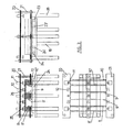
- Figure 4 shows how the support for the first and second thrusting means, arranged on the lower frame 13, consists of respective intermediate parallel beams 27 and 27', on the ends of which are arranged linear bearings 28 and 29 on which the shafts 23 and 24 of the first thrusting means rest, and respective linear bearings 28' and 29' on which the shafts 23' and 24' of the second thrusting means rest.
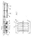
- Figure 6 shows how the drive devices of the operating means comprise two hydraulic cylinders 30 and 30' located near each one of the side runners 5 and 6 of the pallet 1 and connected to the first and second thrusting means respectively by means of tie rods 31 and 31'.
- said tie rods 31 and 31' are bars responsible for respectively connecting the two shafts 23 and 24 to the shafts 23' and 24' of each one of the thrusting means, such that both shafts of each one of the thrusting means move at the same time and therefore said shafts can move, with the same speed, to both ends of each one of the lips 22 and 22' comprising each group of clamps 8, 9 and 10; 8', 9' and 10'.
- the legs 18 of the intermediate frame 14 are vertically adjustable so that the machine assembly can in turn be vertically adjusted and be adapted to the height of the user of the machine in each particular case.
- the pallet 1 will be manually, automatically or semi-automatically supplied to the machine, each one of the runners 5, 6 and 7 thereof being placed between two lips 22 and 22', one of these lips 22 corresponding to the first group of clamps 8, 9 and 10, and the second lip 22' corresponding to the second group of clamps 8', 9' and 10'.
- each one of the blocks 3 forming each runner 5, 6 and 7 rest on the corresponding anvils 19 arranged on the intermediate frame 14 of the support means.
- one of the hydraulic cylinders 30 constituting the operating means of the first group of clamps 8, 9 and 10 acts, positioning the lips 22 corresponding to that first group of clamps 8, 9 and 10 at the original limits of the pallet 1.
- the other hydraulic cylinder 30' for operating the lips 22' of the second group of clamps 8', 9' and 10' acts in the opposite direction.
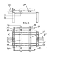
- the thrust force for the first group of clamps 8, 9 and 10, shown in figure 5 by arrow A is greater than the thrust force of the second group of clamps, shown in figure 5 by arrow B.
- This approaching of the lips 22 and 22' of each corresponding group of clamps 8, 9 and 10; 8', 9' and 10' to each one of the runners 5, 6 and 7 of the pallet 1 causes the compression of said runners 5, 6 and 7.
- each one of the runners 5, 6 and 7 of the pallet 1 is thus achieved, and on the other hand, it corrects the lack of squaring which said runners 5, 6 and 7 may have with regard to the upper boards 2 of the pallet, or even with regard to one another, as a result of the flat configuration and the length of the lips 22 and 22' of both group of clamps 8, 9 and 10; 8', 9' and 10'.
- Said hydraulic and pneumatic cylinders make each one of the corresponding rams 25 and 26, which are respectively located on the blocks 3 and on the ends and center of the remaining boards 2' of the upper side of the pallet 1 not resting on the blocks 3, move downwards, definitively driving in any nail which, due to the use of the pallet 1, projects from the surface thereof. All the cylinders act and recover simultaneously, even though their operation may be alternated.
- the machine will need an electric power source and a compressed air source to move the clamps and the different cylinders of the machine. Regulation and control of the machine is carried out by means of a programmable robot (PLC).
- PLC programmable robot
- the invention is additionally provided with a mechanism 32 to ensure the lengthwise limit of the pallet 1, said mechanism comprises a support base 33 located above the pallet 1, two drive cylinders 34 and 34' connected with rotational possibility to said support base 33 by means of respective supports 35, 35', a stop 36 connected to one of the drive cylinders 34 by means of first transmission arms 37, and a compression element 38 connected to the other drive cylinder 34' by means of second transmission arms 37'.
- the support base 33 mainly consists of a flat body having dimensions somewhat larger than those of the pallet 1 at hand.
- the first and second transmission arms 37 and 37' are articulated at one of their ends with regard to their corresponding drive cylinder 34, 34' and connected with rotational possibility, at an intermediate point 39, 39' thereof, to the edges of the support base 33, specifically the edges of the support base 33 perpendicular to the runners 5, 6 and 7 of the pallet 1.
- both the first and second transmission arms 37 and 37' are made up of respective parallel bars 40 and 41; 40' and 41' bent at a certain angle, the vertex of said angle coinciding with the intermediate connection point 39 and 39' of the transmission arms 37 and 37' with the support base 33, the bars 40, 41 of the first transmission arms 37 are connected to one another and to the stop 36 by means of a bar 42 perpendicular to said bars 40, 41, and bars 40', 41' of the second transmission arms 37' are connected to one another and to the compression element 38 by means of another bar 42' perpendicular to said bars 40', 41'.
- the stop 36 connected to the ends of the first transmission arms 37 is also flat and has a width approximately equal to one of the sides of the pallet 1 perpendicular to the runners 5, 6, 7 thereof.
- the compression element 38 connected to the end of the second transmission arms 37' is provided with a thrusting cylinder 43 and a plate 44 set up so as to be operated by said thrusting cylinder 43.
- Said plate 44 has a configuration similar to that of the stop 36 connected to the first transmission arms 37.
- the mechanism 32 for ensuring the lengthwise limit of the pallet 1 is located above the upper frame 15 and the re-nailing elements 11 and 12 and is fixed thereto by means of the support columns 21 arranged on said upper frame 15.
- the drive cylinder 34 connected to the stop 36 acts first as a result of the angular configuration of the transmission arms 37, which rotate with regard to the support base 33, the thrusting of said drive cylinder 34 determines an approaching of the stop 36 to one of the walls of the pallet 1 perpendicular to the runners 5, 6 and 7 thereof, therefore the stop 36 is parallel to said wall, resting against it.
- the other drive cylinder 34' acts on the compression element 38, placing it parallel to the opposite wall of the pallet 1 and at a certain distance, as a result of the configuration of the second transmission arms 37' and the dimensions of the support base 33, which are larger than those of the pallet, slightly projecting therefrom.
- the thrusting cylinder 43 of said compression element 38 acts on the corresponding plate 44 which exerts the desired pressure on said opposite wall, thus ensuring the lengthwise limit of the pallet 1.
Landscapes
- Engineering & Computer Science (AREA)
- Life Sciences & Earth Sciences (AREA)
- Mechanical Engineering (AREA)
- Manufacturing & Machinery (AREA)
- Wood Science & Technology (AREA)
- Forests & Forestry (AREA)
- Dovetailed Work, And Nailing Machines And Stapling Machines For Wood (AREA)
- Pallets (AREA)
Claims (12)
- Maschine zum Formen und Wiedervernageln von Holzpaletten (1), umfassend:- Mittel zum Festhalten und Formen von Paletten;- Wiedervernagelungsmittel;- Stützmittel;- Betätigungsmittel;wobei die Wiedervernagelungsmittel aus einer ersten Gruppe von Wiedervernagelungselementen (11) bestehen, die mit der Position übereinstimmen, die von einem jeden der Blöcke (3) eingenommen wird, welche die Palette (1) bilden, wenn die Palette (1) auf den Festhalte- und Formmitteln positioniert ist, und senkrecht über den Brettern (2) angeordnet sind, die auf den Blöcken (3) aufliegen,
dadurch gekennzeichnet, dass:die Mittel zum Festhalten und Formen von Paletten mit zwei Gruppen von Klemmen versehen sind, einer ersten Gruppe von Klemmen (8, 9, 10), die sich auf einer der Seiten der Läufer (5, 6, 7) befinden, wenn die Palette (1) auf den Festhalte- und Formmitteln positioniert ist, und so ausgelegt sind, dass sie mittels erster Schiebemittel (23, 24) gleichzeitig bewegt werden, und einer zweiten Gruppe von Klemmen (8', 9', 10'), die sich auf der gegenüberliegenden Seite der Läufer (5, 6, 7) befinden, wenn die Palette (1) auf den Festhalte- und Formmitteln positioniert ist, und so ausgelegt sind, dass sie mittels zweiter Schiebemittel (23', 24') in der entgegengesetzten Richtung zu den ersten gleichzeitig bewegt werden, wobei die Schubkraft, die auf die Läufer (5, 6, 7) durch die erste Gruppe von Klemmen (8, 9, 10) ausgeübt wird, größer ist als die Schubkraft, die auf die Läufer durch die zweite Gruppe von Klemmen (8', 9', 10') ausgeübt wird; unddie Wiedervernagelungsmittel ferner eine zweite Gruppe von Wiedervernagelungselementen (12) umfassen, die mit der Position übereinstimmen, die von den Enden und der Mitte der Bretter (2') auf der Oberseite der Palette (1) eingenommen wird, die nicht auf den Blöcken (3) aufliegen, wenn die Palette (1) auf den Festhalte- und Formmitteln positioniert ist, und senkrecht über den Enden und der Mitte angeordnet sind;und dass die Stützmittel aus einem unteren Rahmen (13), einem Zwischenrahmen (14) und einem oberen Rahmen (15) bestehen, wobei der untere Rahmen (13) eine Mehrzahl von Stützbeinen (16) und eine Stütze (17) für die Festhalte- und Formmittel und für die ersten und zweiten Schiebemittel umfasst, der Zwischenrahmen (14) mit einer Mehrzahl von Stützbeinen (18) und mehreren Ambossen (19) oder Verstärkungsplatten versehen ist, auf welchen die Blöcke (3) der Palette (1) aufliegen, und der obere Rahmen (15) mit Stützelementen (20) für die erste und zweite Gruppe von Vernagelungselementen versehen ist und der obere Rahmen (15) so ausgelegt ist, dass er durch den Zwischenrahmen (14) mittels Stützsäulen (21) gestützt wird;wobei die Betätigungsmittel Antriebseinrichtungen (30, 30', 31, 31') für die ersten und zweiten Schiebemittel der Festhalteelemente umfassen. - Maschine zum Formen und Wiedervernageln von Holzpaletten (1) nach Anspruch 1, dadurch gekennzeichnet, dass die erste Gruppe von Klemmen (8, 9, 10) aus einer Mehrzahl von flachen Lippen (22) besteht, die parallel zueinander und zu den Läufern (5, 6, 7) der Palette (1) und senkrecht zur Oberseite der Palette (1) sind, und dass die zweite Gruppe von Klemmen (8', 9', 10') aus einer Mehrzahl von flachen Lippen (22') besteht, die parallel zueinander und zu den ersten sind.
- Maschine zum Formen und Wiedervernageln von Holzpaletten (1) nach Anspruch 2, dadurch gekennzeichnet, dass die Anzahl von Lippen (22, 22') jeder Gruppe von Klemmen (8, 9, 10; 8', 9', 10') gleich der Anzahl von Läufern (5, 6, 7) der Palette (1) ist.
- Maschine zum Formen und Wiedervernageln von Holzpaletten (1) nach Anspruch 3, dadurch gekennzeichnet, dass die Anzahl von Lippen (22, 22') jeder Gruppe von Klemmen (8, 9, 10; 8', 9', 10') gleich drei ist.
- Maschine zum Formen und Wiedervernageln von Holzpaletten (1) nach den vorhergehenden Ansprüchen, dadurch gekennzeichnet, dass die ersten Schiebemittel wenigstens zwei Wellen (23, 24) parallel zueinander umfassen, die an beiden Enden der Unterkante der Lippen (22) der ersten Gruppe von Klemmen (8, 9, 10) befestigt sind, und dass die zweiten Schiebemittel wenigstens zwei Wellen (23', 24') parallel zueinander umfassen, die an beiden Enden der Unterkante der Lippen (22') der zweiten Gruppe von Klemmen (8', 9', 10') befestigt sind.
- Maschine zum Formen und Wiedervernageln von Holzpaletten nach Anspruch 5, dadurch gekennzeichnet, dass sich die Wellen (23', 24') der zweiten Schiebemittel zwischen den Wellen (23, 24) der ersten Schiebemittel befinden.
- Maschine zum Formen und Wiedervernageln von Holzpaletten nach den vorhergehenden Ansprüchen, dadurch gekennzeichnet, dass ein jedes der Elemente (11) der ersten Gruppe von Wiedervernagelungselementen (11) aus einem Stempel (25) besteht, der so aufgebaut ist, dass er durch einen hydraulischen Zylinder betätigt wird, und dass ein jedes der Elemente (12) der zweiten Gruppe von Wiedervernagelungselementen (12) aus einem Stempel (26) besteht, der so aufgebaut ist, dass er durch einen pneumatischen Zylinder betrieben wird.
- Maschine zum Formen und Wiedervernageln von Holzpaletten nach den vorhergehenden Ansprüchen, dadurch gekennzeichnet, dass die Stütze (17) der ersten und zweiten Schiebemittel, die auf dem unteren Rahmen (13) angeordnet ist, aus jeweiligen parallelen Zwischenträgern (27, 27') besteht, auf deren Enden Linearlager (28, 29; 28', 29') angeordnet sind, auf welchen die Wellen (23, 24; 23', 24') der ersten und zweiten Schiebemittel aufliegen.
- Maschine zum Formen und Wiedervernageln von Holzpaletten nach den vorhergehenden Ansprüchen, dadurch gekennzeichnet, dass die Antriebseinrichtungen der Betätigungsmittel zwei hydraulische Zylinder (30, 30') umfassen, die sich in der Nähe eines jeden der Seitenläufer (5, 6) der Palette befinden und mittels jeweiliger Zugstangen (31, 31') mit den ersten beziehungsweise zweiten Schiebemitteln verbunden sind.
- Maschine zum Formen und Wiedervernageln von Holzpaletten nach den vorhergehenden Ansprüchen, dadurch gekennzeichnet, dass die Beine (18) des Zwischenrahmens (14) vertikal verstellbar sind.
- Maschine zum Formen und Wiedervernageln von Holzpaletten nach den vorhergehenden Ansprüchen, dadurch gekennzeichnet, dass sie mit einem Mechanismus (32) zum Sicherstellen der Längsbegrenzung der Palette (1) versehen ist, umfassend eine Stützbasis (33), die sich über der Palette (1) befindet, zwei Antriebszylinder (34, 34'), die mit Drehmöglichkeit mit der Stützbasis (33) mittels einer jeweiligen Stütze (35, 35') verbunden sind, einen Anschlag (36), der mit einem der Antriebszylinder (34) mittels erster Übertragungsarme (37) verbunden ist, und ein Druckelement (38), das mit dem anderen Antriebszylinder (34') mittels zweiter Übertragungsarme (37') verbunden ist, wobei die ersten und zweiten Übertragungsarme (37, 37') an einem ihrer Enden in Bezug auf ihren entsprechenden Zylinder (34, 34') mit Gelenken versehen sind und mit Drehmöglichkeit an einer Zwischenstelle (39, 39') davon mit den Kanten der Stützbasis (33) senkrecht zu den Läufern (5, 6, 7) der Palette (1) verbunden sind, und wobei das Druckelement (38) mit einem Zylinder (43) und einer Platte (44) versehen ist, die so aufgebaut ist, dass sie durch den Schiebezylinder (43) betätigt wird.
- Maschine zum Formen und Wiedervernageln von Holzpaletten (1) nach Anspruch 10, dadurch gekennzeichnet, dass sich der Mechanismus (32), der die Längsbegrenzung der Palette (1) sicherstellt, über dem oberen Rahmen (15) und über den Wiedervernagelungselementen (11, 12) befindet und mittels der Stützsäulen (21), die auf dem oberen Rahmen (15) angeordnet sind, daran befestigt ist.
Priority Applications (3)
| Application Number | Priority Date | Filing Date | Title |
|---|---|---|---|
| AT03380304T ATE386607T1 (de) | 2003-12-22 | 2003-12-22 | Vorrichtung zum formen und wiedernageln von holzpaletten |
| EP03380304A EP1547724B1 (de) | 2003-12-22 | 2003-12-22 | Vorrichtung zum Formen und Wiedernageln von Holzpaletten |
| DE60319246T DE60319246D1 (de) | 2003-12-22 | 2003-12-22 | Vorrichtung zum Formen und Wiedernageln von Holzpaletten |
Applications Claiming Priority (1)
| Application Number | Priority Date | Filing Date | Title |
|---|---|---|---|
| EP03380304A EP1547724B1 (de) | 2003-12-22 | 2003-12-22 | Vorrichtung zum Formen und Wiedernageln von Holzpaletten |
Publications (2)
| Publication Number | Publication Date |
|---|---|
| EP1547724A1 EP1547724A1 (de) | 2005-06-29 |
| EP1547724B1 true EP1547724B1 (de) | 2008-02-20 |
Family
ID=34530856
Family Applications (1)
| Application Number | Title | Priority Date | Filing Date |
|---|---|---|---|
| EP03380304A Expired - Lifetime EP1547724B1 (de) | 2003-12-22 | 2003-12-22 | Vorrichtung zum Formen und Wiedernageln von Holzpaletten |
Country Status (3)
| Country | Link |
|---|---|
| EP (1) | EP1547724B1 (de) |
| AT (1) | ATE386607T1 (de) |
| DE (1) | DE60319246D1 (de) |
Cited By (1)
| Publication number | Priority date | Publication date | Assignee | Title |
|---|---|---|---|---|
| CN104097077A (zh) * | 2014-06-27 | 2014-10-15 | 苏州柏德纳科技有限公司 | 一种牛奶灌装机用工装夹具 |
Families Citing this family (5)
| Publication number | Priority date | Publication date | Assignee | Title |
|---|---|---|---|---|
| TWI371333B (en) * | 2005-11-14 | 2012-09-01 | Holliger Paletten Logistik Ag | Method and apparatus for repairing damaged pallets |
| AU2008200441B8 (en) * | 2008-01-29 | 2011-04-21 | Chep Technology Pty Limited | Lead board adjustment apparatus for a pallet and associated methods |
| CN101885399B (zh) * | 2010-08-18 | 2011-11-16 | 天津商业大学 | 集装堆码专用托盘 |
| CN103659993B (zh) * | 2013-11-18 | 2015-11-25 | 无锡市正阳机械有限公司 | 一种木块定位装置 |
| CN103707379B (zh) * | 2013-11-18 | 2015-11-25 | 无锡市正阳机械有限公司 | 一种双木块定位装置 |
Family Cites Families (3)
| Publication number | Priority date | Publication date | Assignee | Title |
|---|---|---|---|---|
| AU645178B2 (en) * | 1991-03-20 | 1994-01-06 | Brambles Australia Limited | Pallet repair device |
| AU646554B2 (en) * | 1991-04-24 | 1994-02-24 | Brambles Australia Limited | Nail rolling apparatus |
| US5588578A (en) * | 1994-09-02 | 1996-12-31 | Doyle; James J. | Nail flattening apparatus |
-
2003
- 2003-12-22 EP EP03380304A patent/EP1547724B1/de not_active Expired - Lifetime
- 2003-12-22 DE DE60319246T patent/DE60319246D1/de not_active Expired - Lifetime
- 2003-12-22 AT AT03380304T patent/ATE386607T1/de not_active IP Right Cessation
Cited By (1)
| Publication number | Priority date | Publication date | Assignee | Title |
|---|---|---|---|---|
| CN104097077A (zh) * | 2014-06-27 | 2014-10-15 | 苏州柏德纳科技有限公司 | 一种牛奶灌装机用工装夹具 |
Also Published As
| Publication number | Publication date |
|---|---|
| DE60319246D1 (de) | 2008-04-03 |
| EP1547724A1 (de) | 2005-06-29 |
| ATE386607T1 (de) | 2008-03-15 |
Similar Documents
| Publication | Publication Date | Title |
|---|---|---|
| KR101275383B1 (ko) | 손상된 팔레트를 수리하는 방법 및 장치 | |
| US5095605A (en) | Method for making pallets | |
| CN106181420A (zh) | 一种全自动一体式集成型钢生产线 | |
| US3991459A (en) | Pallet disassembling apparatus | |
| EP1547724A1 (de) | Vorrichtung zum Formen und Wiedernageln von Holzpaletten | |
| US4750255A (en) | Machine for disassembling wood pallets | |
| KR20200002239A (ko) | 미성형 포장박스 묶음 해체시스템 | |
| CN202137806U (zh) | 一种全自动台面式人造板纵横锯切机 | |
| US8404069B2 (en) | Method and apparatus for automated stacking of sheet material bundles | |
| CN221606190U (zh) | 一种用于玻璃打包线上机械手的集成取料装置 | |
| US20050089389A1 (en) | Method, system, and apparatus for securing a section of a vertical stack of generally flat sheets, cartons, and like | |
| CN220148619U (zh) | 一种板材加工用码垛设备 | |
| CN218380679U (zh) | 组合烟花角度标准化模具 | |
| CN205575009U (zh) | 一种纸箱生产自动接料码垛装置 | |
| CN217144043U (zh) | 一种包装印刷用纸板剪切装置 | |
| CN216886001U (zh) | 一种用于铝单板镂空雕刻的加工装置 | |
| CN211310160U (zh) | 一种彩票自动去底托板装置 | |
| US5943766A (en) | Machine for inserting stringers into pallets | |
| KR102048242B1 (ko) | 미성형 포장박스 묶음 해체로봇 장치 | |
| US6032351A (en) | Machine for removing stringers from pallets | |
| CN209905249U (zh) | 塑料袋把手自动组装包装机 | |
| KR19990013486A (ko) | 담배용 힌지 덮개식 패킷의 생산방법과 장치 | |
| CN217529002U (zh) | 一种全自动折弯机 | |
| CN221543332U (zh) | 一种具有定位装置的码垛机 | |
| CN209240549U (zh) | 安全智能送料的薄刀分纸压线机 |
Legal Events
| Date | Code | Title | Description |
|---|---|---|---|
| PUAI | Public reference made under article 153(3) epc to a published international application that has entered the european phase |
Free format text: ORIGINAL CODE: 0009012 |
|
| AK | Designated contracting states |
Kind code of ref document: A1 Designated state(s): AT BE BG CH CY CZ DE DK EE ES FI FR GB GR HU IE IT LI LU MC NL PT RO SE SI SK TR |
|
| AX | Request for extension of the european patent |
Extension state: AL LT LV MK |
|
| 17P | Request for examination filed |
Effective date: 20051201 |
|
| AKX | Designation fees paid |
Designated state(s): AT BE BG CH CY CZ DE DK EE ES FI FR GB GR HU IE IT LI LU MC NL PT RO SE SI SK TR |
|
| GRAP | Despatch of communication of intention to grant a patent |
Free format text: ORIGINAL CODE: EPIDOSNIGR1 |
|
| GRAS | Grant fee paid |
Free format text: ORIGINAL CODE: EPIDOSNIGR3 |
|
| GRAA | (expected) grant |
Free format text: ORIGINAL CODE: 0009210 |
|
| AK | Designated contracting states |
Kind code of ref document: B1 Designated state(s): AT BE BG CH CY CZ DE DK EE ES FI FR GB GR HU IE IT LI LU MC NL PT RO SE SI SK TR |
|
| REG | Reference to a national code |
Ref country code: GB Ref legal event code: FG4D |
|
| REG | Reference to a national code |
Ref country code: CH Ref legal event code: EP |
|
| REG | Reference to a national code |
Ref country code: IE Ref legal event code: FG4D |
|
| REF | Corresponds to: |
Ref document number: 60319246 Country of ref document: DE Date of ref document: 20080403 Kind code of ref document: P |
|
| PG25 | Lapsed in a contracting state [announced via postgrant information from national office to epo] |
Ref country code: ES Free format text: LAPSE BECAUSE OF FAILURE TO SUBMIT A TRANSLATION OF THE DESCRIPTION OR TO PAY THE FEE WITHIN THE PRESCRIBED TIME-LIMIT Effective date: 20080531 Ref country code: FI Free format text: LAPSE BECAUSE OF FAILURE TO SUBMIT A TRANSLATION OF THE DESCRIPTION OR TO PAY THE FEE WITHIN THE PRESCRIBED TIME-LIMIT Effective date: 20080220 |
|
| NLV1 | Nl: lapsed or annulled due to failure to fulfill the requirements of art. 29p and 29m of the patents act | ||
| PG25 | Lapsed in a contracting state [announced via postgrant information from national office to epo] |
Ref country code: AT Free format text: LAPSE BECAUSE OF FAILURE TO SUBMIT A TRANSLATION OF THE DESCRIPTION OR TO PAY THE FEE WITHIN THE PRESCRIBED TIME-LIMIT Effective date: 20080220 |
|
| PG25 | Lapsed in a contracting state [announced via postgrant information from national office to epo] |
Ref country code: BE Free format text: LAPSE BECAUSE OF FAILURE TO SUBMIT A TRANSLATION OF THE DESCRIPTION OR TO PAY THE FEE WITHIN THE PRESCRIBED TIME-LIMIT Effective date: 20080220 Ref country code: SI Free format text: LAPSE BECAUSE OF FAILURE TO SUBMIT A TRANSLATION OF THE DESCRIPTION OR TO PAY THE FEE WITHIN THE PRESCRIBED TIME-LIMIT Effective date: 20080220 |
|
| PG25 | Lapsed in a contracting state [announced via postgrant information from national office to epo] |
Ref country code: SK Free format text: LAPSE BECAUSE OF FAILURE TO SUBMIT A TRANSLATION OF THE DESCRIPTION OR TO PAY THE FEE WITHIN THE PRESCRIBED TIME-LIMIT Effective date: 20080220 Ref country code: CZ Free format text: LAPSE BECAUSE OF FAILURE TO SUBMIT A TRANSLATION OF THE DESCRIPTION OR TO PAY THE FEE WITHIN THE PRESCRIBED TIME-LIMIT Effective date: 20080220 Ref country code: DK Free format text: LAPSE BECAUSE OF FAILURE TO SUBMIT A TRANSLATION OF THE DESCRIPTION OR TO PAY THE FEE WITHIN THE PRESCRIBED TIME-LIMIT Effective date: 20080220 Ref country code: NL Free format text: LAPSE BECAUSE OF FAILURE TO SUBMIT A TRANSLATION OF THE DESCRIPTION OR TO PAY THE FEE WITHIN THE PRESCRIBED TIME-LIMIT Effective date: 20080220 Ref country code: PT Free format text: LAPSE BECAUSE OF FAILURE TO SUBMIT A TRANSLATION OF THE DESCRIPTION OR TO PAY THE FEE WITHIN THE PRESCRIBED TIME-LIMIT Effective date: 20080721 Ref country code: SE Free format text: LAPSE BECAUSE OF FAILURE TO SUBMIT A TRANSLATION OF THE DESCRIPTION OR TO PAY THE FEE WITHIN THE PRESCRIBED TIME-LIMIT Effective date: 20080520 |
|
| PG25 | Lapsed in a contracting state [announced via postgrant information from national office to epo] |
Ref country code: RO Free format text: LAPSE BECAUSE OF FAILURE TO SUBMIT A TRANSLATION OF THE DESCRIPTION OR TO PAY THE FEE WITHIN THE PRESCRIBED TIME-LIMIT Effective date: 20080220 |
|
| EN | Fr: translation not filed | ||
| PLBE | No opposition filed within time limit |
Free format text: ORIGINAL CODE: 0009261 |
|
| STAA | Information on the status of an ep patent application or granted ep patent |
Free format text: STATUS: NO OPPOSITION FILED WITHIN TIME LIMIT |
|
| 26N | No opposition filed |
Effective date: 20081121 |
|
| PG25 | Lapsed in a contracting state [announced via postgrant information from national office to epo] |
Ref country code: DE Free format text: LAPSE BECAUSE OF FAILURE TO SUBMIT A TRANSLATION OF THE DESCRIPTION OR TO PAY THE FEE WITHIN THE PRESCRIBED TIME-LIMIT Effective date: 20080521 |
|
| PG25 | Lapsed in a contracting state [announced via postgrant information from national office to epo] |
Ref country code: FR Free format text: LAPSE BECAUSE OF FAILURE TO SUBMIT A TRANSLATION OF THE DESCRIPTION OR TO PAY THE FEE WITHIN THE PRESCRIBED TIME-LIMIT Effective date: 20081212 Ref country code: BG Free format text: LAPSE BECAUSE OF FAILURE TO SUBMIT A TRANSLATION OF THE DESCRIPTION OR TO PAY THE FEE WITHIN THE PRESCRIBED TIME-LIMIT Effective date: 20080520 Ref country code: EE Free format text: LAPSE BECAUSE OF FAILURE TO SUBMIT A TRANSLATION OF THE DESCRIPTION OR TO PAY THE FEE WITHIN THE PRESCRIBED TIME-LIMIT Effective date: 20080220 |
|
| PG25 | Lapsed in a contracting state [announced via postgrant information from national office to epo] |
Ref country code: MC Free format text: LAPSE BECAUSE OF NON-PAYMENT OF DUE FEES Effective date: 20081231 Ref country code: CY Free format text: LAPSE BECAUSE OF FAILURE TO SUBMIT A TRANSLATION OF THE DESCRIPTION OR TO PAY THE FEE WITHIN THE PRESCRIBED TIME-LIMIT Effective date: 20080220 |
|
| REG | Reference to a national code |
Ref country code: CH Ref legal event code: PL |
|
| GBPC | Gb: european patent ceased through non-payment of renewal fee |
Effective date: 20081222 |
|
| PG25 | Lapsed in a contracting state [announced via postgrant information from national office to epo] |
Ref country code: IT Free format text: LAPSE BECAUSE OF FAILURE TO SUBMIT A TRANSLATION OF THE DESCRIPTION OR TO PAY THE FEE WITHIN THE PRESCRIBED TIME-LIMIT Effective date: 20080220 |
|
| PG25 | Lapsed in a contracting state [announced via postgrant information from national office to epo] |
Ref country code: IE Free format text: LAPSE BECAUSE OF NON-PAYMENT OF DUE FEES Effective date: 20081222 Ref country code: CH Free format text: LAPSE BECAUSE OF NON-PAYMENT OF DUE FEES Effective date: 20081231 Ref country code: LI Free format text: LAPSE BECAUSE OF NON-PAYMENT OF DUE FEES Effective date: 20081231 |
|
| PG25 | Lapsed in a contracting state [announced via postgrant information from national office to epo] |
Ref country code: GB Free format text: LAPSE BECAUSE OF NON-PAYMENT OF DUE FEES Effective date: 20081222 |
|
| PG25 | Lapsed in a contracting state [announced via postgrant information from national office to epo] |
Ref country code: LU Free format text: LAPSE BECAUSE OF NON-PAYMENT OF DUE FEES Effective date: 20081222 Ref country code: HU Free format text: LAPSE BECAUSE OF FAILURE TO SUBMIT A TRANSLATION OF THE DESCRIPTION OR TO PAY THE FEE WITHIN THE PRESCRIBED TIME-LIMIT Effective date: 20080821 |
|
| PG25 | Lapsed in a contracting state [announced via postgrant information from national office to epo] |
Ref country code: TR Free format text: LAPSE BECAUSE OF FAILURE TO SUBMIT A TRANSLATION OF THE DESCRIPTION OR TO PAY THE FEE WITHIN THE PRESCRIBED TIME-LIMIT Effective date: 20080220 |
|
| PG25 | Lapsed in a contracting state [announced via postgrant information from national office to epo] |
Ref country code: GR Free format text: LAPSE BECAUSE OF FAILURE TO SUBMIT A TRANSLATION OF THE DESCRIPTION OR TO PAY THE FEE WITHIN THE PRESCRIBED TIME-LIMIT Effective date: 20080521 |