EP1547681A2 - Durchflussgeregeltes Gerät für ein mikrowellenunterstütztes chemisches Verfahren - Google Patents
Durchflussgeregeltes Gerät für ein mikrowellenunterstütztes chemisches Verfahren Download PDFInfo
- Publication number
- EP1547681A2 EP1547681A2 EP04255177A EP04255177A EP1547681A2 EP 1547681 A2 EP1547681 A2 EP 1547681A2 EP 04255177 A EP04255177 A EP 04255177A EP 04255177 A EP04255177 A EP 04255177A EP 1547681 A2 EP1547681 A2 EP 1547681A2
- Authority
- EP
- European Patent Office
- Prior art keywords
- vessel
- microwave
- reaction vessel
- pressure
- reaction
- Prior art date
- Legal status (The legal status is an assumption and is not a legal conclusion. Google has not performed a legal analysis and makes no representation as to the accuracy of the status listed.)
- Granted
Links
Images


Classifications
-
- B—PERFORMING OPERATIONS; TRANSPORTING
- B01—PHYSICAL OR CHEMICAL PROCESSES OR APPARATUS IN GENERAL
- B01J—CHEMICAL OR PHYSICAL PROCESSES, e.g. CATALYSIS OR COLLOID CHEMISTRY; THEIR RELEVANT APPARATUS
- B01J19/00—Chemical, physical or physico-chemical processes in general; Their relevant apparatus
- B01J19/08—Processes employing the direct application of electric or wave energy, or particle radiation; Apparatus therefor
- B01J19/12—Processes employing the direct application of electric or wave energy, or particle radiation; Apparatus therefor employing electromagnetic waves
- B01J19/122—Incoherent waves
- B01J19/126—Microwaves
-
- B—PERFORMING OPERATIONS; TRANSPORTING
- B01—PHYSICAL OR CHEMICAL PROCESSES OR APPARATUS IN GENERAL
- B01J—CHEMICAL OR PHYSICAL PROCESSES, e.g. CATALYSIS OR COLLOID CHEMISTRY; THEIR RELEVANT APPARATUS
- B01J4/00—Feed or outlet devices; Feed or outlet control devices
- B01J4/02—Feed or outlet devices; Feed or outlet control devices for feeding measured, i.e. prescribed quantities of reagents
-
- H—ELECTRICITY
- H05—ELECTRIC TECHNIQUES NOT OTHERWISE PROVIDED FOR
- H05B—ELECTRIC HEATING; ELECTRIC LIGHT SOURCES NOT OTHERWISE PROVIDED FOR; CIRCUIT ARRANGEMENTS FOR ELECTRIC LIGHT SOURCES, IN GENERAL
- H05B6/00—Heating by electric, magnetic or electromagnetic fields
- H05B6/64—Heating using microwaves
- H05B6/6408—Supports or covers specially adapted for use in microwave heating apparatus
-
- H—ELECTRICITY
- H05—ELECTRIC TECHNIQUES NOT OTHERWISE PROVIDED FOR
- H05B—ELECTRIC HEATING; ELECTRIC LIGHT SOURCES NOT OTHERWISE PROVIDED FOR; CIRCUIT ARRANGEMENTS FOR ELECTRIC LIGHT SOURCES, IN GENERAL
- H05B6/00—Heating by electric, magnetic or electromagnetic fields
- H05B6/64—Heating using microwaves
- H05B6/80—Apparatus for specific applications
- H05B6/806—Apparatus for specific applications for laboratory use
-
- B—PERFORMING OPERATIONS; TRANSPORTING
- B01—PHYSICAL OR CHEMICAL PROCESSES OR APPARATUS IN GENERAL
- B01J—CHEMICAL OR PHYSICAL PROCESSES, e.g. CATALYSIS OR COLLOID CHEMISTRY; THEIR RELEVANT APPARATUS
- B01J2219/00—Chemical, physical or physico-chemical processes in general; Their relevant apparatus
- B01J2219/00049—Controlling or regulating processes
- B01J2219/00164—Controlling or regulating processes controlling the flow
-
- B—PERFORMING OPERATIONS; TRANSPORTING
- B01—PHYSICAL OR CHEMICAL PROCESSES OR APPARATUS IN GENERAL
- B01J—CHEMICAL OR PHYSICAL PROCESSES, e.g. CATALYSIS OR COLLOID CHEMISTRY; THEIR RELEVANT APPARATUS
- B01J2219/00—Chemical, physical or physico-chemical processes in general; Their relevant apparatus
- B01J2219/08—Processes employing the direct application of electric or wave energy, or particle radiation; Apparatus therefor
- B01J2219/12—Processes employing electromagnetic waves
- B01J2219/1203—Incoherent waves
- B01J2219/1206—Microwaves
- B01J2219/1209—Features relating to the reactor or vessel
- B01J2219/1212—Arrangements of the reactor or the reactors
- B01J2219/1218—Multiple reactors
-
- B—PERFORMING OPERATIONS; TRANSPORTING
- B01—PHYSICAL OR CHEMICAL PROCESSES OR APPARATUS IN GENERAL
- B01J—CHEMICAL OR PHYSICAL PROCESSES, e.g. CATALYSIS OR COLLOID CHEMISTRY; THEIR RELEVANT APPARATUS
- B01J2219/00—Chemical, physical or physico-chemical processes in general; Their relevant apparatus
- B01J2219/08—Processes employing the direct application of electric or wave energy, or particle radiation; Apparatus therefor
- B01J2219/12—Processes employing electromagnetic waves
- B01J2219/1203—Incoherent waves
- B01J2219/1206—Microwaves
- B01J2219/1209—Features relating to the reactor or vessel
- B01J2219/1221—Features relating to the reactor or vessel the reactor per se
- B01J2219/1239—Means for feeding and evacuation
-
- B—PERFORMING OPERATIONS; TRANSPORTING
- B01—PHYSICAL OR CHEMICAL PROCESSES OR APPARATUS IN GENERAL
- B01J—CHEMICAL OR PHYSICAL PROCESSES, e.g. CATALYSIS OR COLLOID CHEMISTRY; THEIR RELEVANT APPARATUS
- B01J2219/00—Chemical, physical or physico-chemical processes in general; Their relevant apparatus
- B01J2219/08—Processes employing the direct application of electric or wave energy, or particle radiation; Apparatus therefor
- B01J2219/12—Processes employing electromagnetic waves
- B01J2219/1203—Incoherent waves
- B01J2219/1206—Microwaves
- B01J2219/1248—Features relating to the microwave cavity
- B01J2219/1251—Support for the reaction vessel
- B01J2219/126—Support for the reaction vessel in the form of a closed housing
Definitions
- the present invention relates to microwave-assisted chemical processes and in particular relates to microwave-assisted chemical synthesis, carried out in automated, controlled-flow fashion, using heterogeneous and high-viscosity compositions and while providing for high pressure reactions.
- microwaves to provide energy to initiate, drive or control chemical reactions
- microwaves can be used to affect a wide variety of chemical reactions
- the commercial use of microwave assisted chemistry initially grew most rapidly in techniques such as loss-on-drying (gravimetric) moisture analysis and digestion reactions that provided the foundation for content analysis. Indeed, such reactions still represent a major part of the instrument market for microwave assisted chemistry.
- gravimetric analysis and digestion can often be carried out in rather robust fashion, for which the longer wavelengths and broad control parameters of microwaves are well-suited.
- microwaves react immediately with polar and semi-polar materials, they help avoid the lag time inherent in other forms of energy transfer such as conduction or convection heating. Thus, they offer a time advantage for many research schemes including those broadly referred to as "combinatorial chemistry.”
- electromagnetic radiation in the microwave frequencies can affect individual molecules (and thus compositions) somewhat differently--and thus potentially more favorably--than convention or conduction heating.
- single mode cavity microwave instruments have become commercially available that are well-suited for controlled application of microwave radiation to small samples. These include the VOYAGERTM, DISCOVERTM, and EXPLORERTM instruments available from CEM Corporation, Matthews, NC, for which more formal descriptions are set forth (but not limited to) U.S. Published Patent Applications Nos. 20040020923, 20030199099, 20030089706, and 20020117498; and U.S. Patents Nos. 6,744,024; 6,607,920; and 6,521,876.
- the batch systems can handle high pressure and heterogeneous starting materials, but cannot offer continuous operation from a reactant source.
- the flow-through systems can use reactants and generate products on a continuous basis, but generally cannot handle (because of pumping or flow considerations) heterogeneous starting materials or high viscosity fluids, or do so at high pressures.
- conventional HPLC pumps cannot handle higher viscosity liquids or any solids whatsoever.
- the available flow rates raise specific problems in microwave assisted chemistry. Higher flow rates help move solids through the instrument but reduce the available time spent in the microwave field.
- Lower flow rates will (mathematically at least) increase residence time in the microwave field, but tend to encourage heterogeneous mixtures (typically liquid reactants and solvents in combination with solid-phase catalysts or solid-supported reagents) to separate into their respective phases before reacting properly or, in severe cases, blocking the flow path and rendering the instrument temporarily or permanently unusable.
- heterogeneous mixtures typically liquid reactants and solvents in combination with solid-phase catalysts or solid-supported reagents
- Flow-through devices also lack a stirring capability, which can be particularly important for heterogeneous mixtures.
- precise temperature control (as opposed to consistent application of microwave radiation) is different or impossible in flow-through systems.
- many prior flow-through systems require multimode cavities or otherwise operate in multimode fashion.
- conventional flow-through systems can often handle homogeneous liquids at high pressure or heterogeneous mixtures at low pressures, but cannot provide a continuous flow reaction system for carrying out high pressure reactions on heterogeneous materials. Because higher pressures (e.g . up to 250 psi or more) are advantageous to or necessary for certain reaction schemes, the ability to carry them out on an automated or flow through basis presents a function disadvantage.
- U.S. Patent No. 5,387,397 to Strauss discloses a flow-through microwave instrument that can nominally provide "a continuous and pressurized feed of liquid or slurry to and through a microwave heating zone" (column 2, lines 46-47).
- a microwave heating zone column 2, lines 46-47.
- line 62 uses a finely ground starting material in a solvent
- phenyl vinyl ketone at column 12 linel6 describes a suspension of 5 grams of starting material in 400 milliliters of water.
- Other examples may create heterogeneous mixtures, but if so, Strauss does not appear to focus upon them.
- Strauss are in the neighborhood of about one percent by weight of the otherwise liquid volume being pumped.
- Strauss refers to pressure control, it is in the nature of a continuous flow system and does not provide for extended residence times.
- Katschnig No. 5,403,564 describes a microwave system for thermal decontamination of "pumpable or pourable” material, but essentially operates at between about one and two atmospheres.
- Knapp No. 5,672,316 describes a flow-through system in which higher pressure is equilibrated by placing a flow path within a pressure-containing vessel while leaving one end of the flow path open to the interior of the vessel and a reservoir of liquid in the vessel to thereby cause the pressure on the inside and the outside of the flow path to be identical.
- Haswell No. 5,215,715 which is commonly assigned with the present invention, describes a flow-through system in which samples to be digested are moved through a microwave cavity as discreet slugs at pressures of between about 30 and 120 pounds per square inch (PSI).
- PSD pounds per square inch
- the Haswell instrument is primarily for digestion rather than chemical synthesis as indicated by the nature of the flow-through system and the manner in which the slug and solvent are pumped through it.
- Renoe No. 5,420,039 which is also commonly assigned with the present invention, describes a flow-through system in which water is pumped through at high pressure, but an ordinary sample is carried by the water rather than being pressurized.
- pressure is controlled in the '039 patent for the purpose of keeping gasses dissolved in a liquid sample so that the liquid sample can be consistently evaluated using a capacitance detection system.
- the invention is a controlled-flow microwave instrument for chemical synthesis that includes (or generates) heterogeneous or highly viscous materials, including starting materials.
- the instrument includes a microwave source for generating electromagnetic radiation in the microwave frequencies, a microwave cavity in wave communication with the source for exposing compositions placed in the cavity to microwave radiation, a microwave-transparent pressure resistant reaction vessel in the cavity, a source reservoir for starting materials and related compositions, a pump in communication with the source reservoir for pumping heterogeneous or highly viscous materials from the source to the reaction vessel, and a pressure-resistant valve between the pump and the reaction vessel for isolating the reaction vessel from the pump and the source during application of microwave energy to compositions in the vessel and from any resulting high pressures generated therein.
- FIG 1 is a schematic diagram of a controlled-flow microwave instrument for chemical synthesis using heterogeneous or highly viscous starting materials.
- the instrument comprises a microwave source designated at 10 for generating electromagnetic radiation in the microwave frequencies.
- a microwave cavity 11 is in wave communication with the source 10 for exposing compositions placed therein to microwave radiation.
- the cavity 11 and the source 10 communicate through a waveguide 12.
- the microwave cavity 10 is a single or dual mode cavity. Single and dual mode cavities are preferred because the value of the microwave field is predetermined at particular positions in the cavity on a consistent and reproducible basis.
- a microwave transparent pressure resistant reaction vessel 13 is positioned (partially or entirely) within the cavity 11. Although it is sufficient for a portion of the vessel 13 to be transparent to microwave radiation, in preferred embodiments, the entire reaction vessel is transparent with the possible exception of an appropriate pressure fitting or cap illustrated at 14 in Figure 1.
- the most preferred materials for the reaction vessel 13 are typically quartz, glass, or engineering plastics.
- the pressure resistant reaction vessel 13 has sufficient strength to maintain reactions therein at pressures of at least about 175 lbs. per square inch (psi). In the most preferred embodiments, the pressure-resistant reaction vessel 13 has strength sufficient to maintain pressures of at least about 250 lbs. per square inch, as well as all incremental pressures between 175 and 250 psi.
- Figure 1 illustrates two source reservoirs 15 and 16 for starting materials and related compositions such as catalysts, solvents and solid-supported reagents.
- starting materials and related compositions such as catalysts, solvents and solid-supported reagents.
- the reservoirs 15 and 16 communicate with other portions of the instrument through the respective fluid lines 21 and 29.
- the term "reservoir” is used in a broad sense herein and does not necessarily refer to a particular type of container or vessel. Instead, the term can apply to any source of starting material, solvent, catalyst or any other composition that may used in the reaction and pumped through the instrument in the manner described herein.
- Peristaltic pumps are generally well-understood in this (and other arts) and are commercially available from a wide variety of sources and will not be otherwise described in detail herein.
- peristaltic pump is preferred, other types of pumps can be used if desired or necessary with typical examples being diaphragm pumps or pneumatic pumps. These are likewise well understood in the art and will not be described in detail herein. Any pump is appropriate provided that it carries out its pumping function in accordance with the remainder of the operation of the instrument.
- Figure 1 also illustrates that the instrument comprises a temperature detector illustrated at 24 associated with the cavity 11 for measuring the temperature of the vessel 13 or its contents.
- the instrument also comprises means for adjusting the microwave power applied from the source 10 to the cavity 11.
- the adjusting means is illustrated at 27 and can comprise (for example) a switching power supplying as set forth and commonly assigned U.S. Patent No. 6,288,379, or an optical lens system as set forth and commonly assigned U.S. Patent No. 5,796,080.
- the switching power supply moderates the applied microwaves by moderating the power supplied to the source 10.
- the lens system moderates the microwaves after they are generated and as they are propagated into the waveguide 12 and then into the cavity 11.
- Figure 1 illustrates that the instrument most preferably includes a processor illustrated at 26 in operative communication with the temperature detector 24 and the adjusting means 27 for adjusting the microwaves applied from the source 10 to the cavity 11 in response to the temperature measured by the detector 24.
- the temperature detector 24 is an infrared optical detector which measures the wavelength of infrared radiation produced by the vessel 13 or its contents and converts this into an electrical signal which is carried by signal line 25 to the processor 26. In this manner, the temperature detector can be used to help moderate, control, or maintain a constant temperature within the cavity 11 or for the vessel 13 or its contents as may be desired or necessary for some or all portions of a chemical reaction scheme.
- the instrument also preferably comprises means shown as the fan 30 for cooling the vessel (and thus its contents) in the cavity at any time, but particularly during the application of microwaves.
- the fan 30 includes an air intake 31 and an output 32 for directing a flow of cooling air into the cavity 11.
- Other cooling fluids can also be used, including an inert gas maintained at a desired low-temperature.
- the microwave radiation can drive or control the reaction in a desired manner, while keeping the vessel's contents below a temperature that would allow the reaction to proceed in an undesired manner or potentially decompose sensitive reactants or products.
- the reaction of interest may not need to be cooled during the application of microwaves, but the cooling function can be carried out after the reaction is complete for the purpose of cooling the vessel and its contents and reducing the internal pressure prior to opening the vessel in the manner described later herein.
- the instrument has the capability of cooling the cavity, the vessel and the vessel's contents at any time, but the ability to do so during the application of microwave radiation is particularly useful in carrying out certain reactions.
- the fan 30 is in operative communication through the signal line 33 with the processor 26 to thereby operate the fan 30 in response to the temperature measured by the temperature detector.
- the microwave source 10 is selected from the group consisting of magnetrons, klystrons, and solid-state devices.
- Magnatrons are often commercially preferred because of their well-understood operation, wide availability, moderate size, and appropriate cost. These tend to be commercial factors, however, and are not limiting of the scope of the invention.
- the instrument includes a pressure resistant valve designated at 34 in Figure 1.
- the pressure-resistant valve 34 is positioned between the peristaltic pump 17 and the reaction vessel 13 for isolating the reaction vessel 13 from the pump 17 and from the source 15 during application of microwave energy to compositions in the vessel 13 and for isolating the reaction vessel from the lower pressure portions of the instrument when high pressures are generated in the reaction vessel 13 as a result of the chemical reactions being carried out therein.
- the pressure resistant valve comprises a ball valve that is pressure resistant to at least about 175 psi and preferably to at least about 250 psi, and to all pressure increments therebetween. In most circumstances, the pressure resistance of the valve 34 should at least match, and preferably exceed, that of the reaction vessel 13.
- the valve 34 communicates with the vessel 13 through at least one fluid line illustrated at 28 in Figure 1.
- the fluid line 28 preferably extends to a point near the bottom of the vessel 13 to thus permit materials to be delivered to, and more importantly pumped from, the bottom portions of the vessel 13.
- a gas line (23 in Figure 1) is positioned in upper portions of the vessel 13 in order to best deliver an inert gas to the vessel to help push materials from the vessel after chemical reactions therein are completed.
- the various fluid lines used in the instrument can be selected as may be desired or necessary for various purposes.
- the lines are formed of materials that are chemically inert to the materials being transferred therethrough and mechanically strong enough to withstand the desired or necessary pressures.
- glass, metal and polymers are all satisfactory candidate materials, with various fluorinated hydrocarbon polymers (e.g., polytetrafluoroethylene and related polymers) being particularly suitable.
- the lines 23, 28 between the ball valve 34 and the vessel 13 should, of course, be strong enough to withstand the expected high pressures generated by reactions in the vessel 13 and necessarily maintained between the vessel 13 and the ball valve 34.
- the peristaltic pump 17 is a two-way pump for adding materials to and pumping materials from the reaction vessel 13.
- the instrument further comprises a multi-port valve broadly designated at 36 and positioned between the source reservoirs 15, 16 and the peristaltic pump 17 for controlling the flow of materials to and from the reaction vessel 13.
- Fluid line 20 connects the multi-port valve 36 to the pump 17.
- the multi-port (multi-function, multi-position) valve 36 is also in fluid communication with a product reservoir 37 through fluid line 40.
- the multi-port valve 36 is also in communication with a processor (preferably the common processor 26), that is also in operative communication with the peristaltic pump 17 and the valve 36, for directing the flow of materials to and from the multi-port valve 36, the two-way pump 17, and the reaction cell 13.
- a processor preferably the common processor 26
- Figure 1 illustrates that the valve 36 is in signal communication with the processor 26 through the signal line 41, and that the processor 26 is in communication with the peristaltic pump 17 through the signal line 42.
- Figure 1 also illustrates a plurality of fluid lines, some of which have already been designated with reference numerals, for providing the fluid communication described herein within the instrument.
- the instrument further comprises a solvent supply 43 that connects to the valve 36 through the fluid line 44 for providing solvent to the reaction cell, or for rinsing and cleaning the various fluid lines, or both.
- a vent 45 is also in fluid communication with the multi-port valve 36 through fluid lines 46, gate (or equivalent) valve 47, and fluid lines 50 and 51.
- a waste reservoir 52 is also in fluid communication with the multi-port valve 36 through the fluid line 53 for receiving waste product, for example after rinsing ("backwashing").
- some of the fluid transfer is carried out using an inert (i.e. chemically inert to the instruments and the reactions and the materials in the reactions) from a gas supply 54, which also communicates with the valve 36 through the fluid line 51.
- an inert i.e. chemically inert to the instruments and the reactions and the materials in the reactions
- gas supply 54 which also communicates with the valve 36 through the fluid line 51.
- pressurized gas from the supply 54 can be used to push solvent through the respective lines in one or opposite directions as desired or necessary.
- gas from the supply 54 can also be added to the vessel 13, either as a reactant or as an inert gas to help pump materials from the vessel 13.
- the instrument also optionally includes a fluid level detector 38 that adds additional automated features to the instrument.
- a fluid level detector 38 that adds additional automated features to the instrument.
- one or two fluid level detectors 38 can be included, with only one illustrated in Figure 1. When a single detector is used, it will detect the start ("head") of fluid flow from one of the reservoirs of 15, 16 toward the vessel 13. It can also detect the end of the flow (tail) and thus confirm that an appropriate amount of liquid has been added to the vessel. Because the processor 26 is programmed to know or select the amount of liquid being added to the vessel 13, the time period that extends between the head of the liquid flowing past the detector 38 and the tail of the liquid flowing past the detector 38 should correspond to the amount of liquid being sent to the vessel 13. If this differs from the amount calculated or desired by the processor, the instrument can be shut down until an operator can make the appropriate corrections or adjustments.
- the detection of the head or tail of the fluid flow from one of the detectors to the next can also be used to calculate a flow rate which can be useful or necessary in a number of circumstances.
- FIG 2 is a perspective view of a commercial embodiment of the instrument shown schematically in Figure 1.
- the instrument is broadly designated at 9, and includes a lower housing 18 and an upper housing 19.
- the cavity 11 is within the lower housing 18 and its location is broadly designated at 11.
- the portion of the instrument 9 that is included in the lower housing 18 is substantially identical to CEM's DISCOVERTM instrument which is described on CEM's web site (www.cem.com) and set forth in several of the previously-incorporated patents and applications.
- Portions of the vessel 13 are positioned in the cavity 11 and the vessel 13 includes a pressure lid or cap 14 with various liquid and gas fittings attached to it, which for the sake of clarity are not separately numbered in Figure 2.
- Figure 2 similarly illustrates a series of containers that correspond to those shown schematically in Figure 1. These include the solvent reservoir supply 43, the starting material reservoirs 15 and 16, the product reservoir 37 and the waste reservoir 52. These all are respectively connected to the multi-port valve 36 using the various fluid lines as described in Figure 1 and carrying the same reference numerals.
- the peristaltic pump 17 is positioned within the upper housing 19.
- the multi-port valve 36 and the ball valve 34 are illustrated in Figure 2 and carry the same reference numerals as Figure 1.
- the upper housing 19 carries several various motors and (if necessary) associated gear or drive movements that drive the peristaltic pump 17, the ball valve and 34 and the multi-port valve 36.
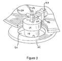
- Figure 3 is an enlarged view of a portion of Figure 2 that shows the top of the vessel 13 in more detail.
- Figure 3 also illustrates a lock 56 and associated safety knob 57 that work in conjunction with a check valve 60 to prevent unintended release of high pressure gases from the vessel 13.
- the lock 56 prevents the cap 14 from being removed from the vessel 13 until the safety knob 57 has been opened to allow pressure to escape through the check valve 60.
- the lock 56 and the knob 57 prevent the lid 14 from being removed from the vessel 13 when high pressures remain within the vessel 13.
- Figure 3 also shows the attenuator 61 on below the adapter plate 62.
- a number of the fluid and gas lines particularly 23 and 28 are also illustrated in the view of Figure 3.
- the instrument can be used in an automated fashion to carry out two or more identical or different reactions in sequence.
- the number of reactions that can be carried at in sequence is not limited by the processor or the vessel, but primarily by the number and type of reservoirs, fluid lines and valves that are included in any particular version of the device.
- the processor 26 can be programmed to carry out several reactions in sequence by selectively pumping specific starting materials from particular reservoirs at particular times to the reaction vessel and then exposing those materials to microwave radiation.
- the vessel 13, the various fluid lines, and the valves 34 and 36 can be rinsed if necessary or desired with solvent from the solvent reservoir 43.
- Rinsing is optional, of course, and may not need to be carried out between all reactions, but the instrument provides the opportunity to carry out rinsing in manual or automated fashion as may be desired.
- the invention is a method of conducting microwave assisted chemical reactions using high viscosity liquids or heterogeneous mixtures of liquids and solids. It will be understood that although the invention (as both instrument and method) is best described in terms of its capabilities of handling highly viscous liquids and heterogeneous mixtures, the invention is not limited to such materials, and homogeneous, free-flowing liquids (including compounds and solutions) can be used as well.
- the method comprises pumping a discrete portion of a composition selected from the group consisting of high viscosity liquids and heterogeneous mixtures of liquids and solids to a microwave transparent pressure resistant reaction vessel at ambient pressures of between about atmospheric pressure and about 30 psi.
- the discrete portion is then isolated in the pressure resistant vessel, following which microwave radiation is applied to the isolated discrete portion in the reaction vessel to initiate and maintain a chemical reaction at a pressure of at least about 175 psi while preventing the vessel from releasing higher-pressure gases generated by a chemical reaction in the vessel.
- Pressure is next released from the vessel following desired completion of the chemical reaction and the reaction products of the discrete portion are pumped from the vessel at ambient pressures of between about atmospheric pressure and about 30 psi following the pressure release.
- the method comprises pumping a second discrete portion after the first portion has been pumped out on the reaction vessel and thereafter carrying out the steps of isolating the second portion, applying microwave radiation to the second portion, releasing pressure from the vessel, and pumping reaction products from the vessel.
- the method can further comprise stirring the discrete portion in the reaction vessel during the step of applying microwave radiation.
- Figure 1 does not illustrate such a stirrer, but it will be understood that a very typical and exemplary technique is to include a Teflon-coated magnetic stirrer bar in the vessel and to rotate it using an external magnet beneath or adjacent the vessel.
- the step of applying microwave radiation preferably comprises applying single or dual modes rather than multiple modes in the cavity.
- Those familiar with microwave modes will recognize that the establishment of a specific single or duel mode in a particular cavity is a function of the wavelength (frequency) of the microwaves and the dimensions, potentially including the shape, of the cavity into which the microwaves are propagated. Differently shaped cavities can be incorporated with different wavelengths to produce a single or dual-mode of radiation.
- the single mode cavities that are described and set forth in the commonly assigned and previously-incorporated patents and applications are exemplary.
- the method can also comprise, and often typically comprises, maintaining their reaction vessel at a constant temperature for an extended portions of a chemical reaction, recognizing of course that the reaction will need to heat up to such temperature on as an initial part of the reaction scheme.
- the method also comprises measuring the temperature of the reaction vessel or of its contents, and then adjusting the application of microwave radiation in response to the measured temperature.
- the method also preferably comprises the step of measuring the temperature of the reaction vessel or its contents and cooling the reaction vessel in response to the measure temperature so that the combination of adjusting the applied or propagated microwave radiation and the application of cooling keeps the reaction subject to a desired amount of microwave radiation but at a desired fixed temperature.
- the method comprises maintaining the pressure in the reaction vessel at between about 175 and 250 psi as this range tends to be the temperature and pressure range at which a number of chemical reactions proceed most favorably.
- the method can also comprise rinsing or backwashing the reaction vessel with a solvent between the steps of pumping the first reaction products and pumping the second discrete portion.
- the method comprises driving the rinsing solvent with an inertr gas.
- inert does not necessarily (although it can) refer to the noble gases, but includes any appropriate gas that does not disadvantageously react with the instrument, the reactants, or the products. In many (but not necessarily all) applications nitrogen is an appropriate inert gas for these purposes.
- the method preferably comprises mixing the composition to be pumped and exposed to microwaves from components selected from the group consisting of solids, liquids, solutions, solid phase catalysts and solid-supported reagents prior to the step of pumping the composition to the reaction vessel.
Landscapes
- Chemical & Material Sciences (AREA)
- Physics & Mathematics (AREA)
- Electromagnetism (AREA)
- Organic Chemistry (AREA)
- Chemical Kinetics & Catalysis (AREA)
- Health & Medical Sciences (AREA)
- General Health & Medical Sciences (AREA)
- Toxicology (AREA)
- Clinical Laboratory Science (AREA)
- Physical Or Chemical Processes And Apparatus (AREA)
- Organic Low-Molecular-Weight Compounds And Preparation Thereof (AREA)
Applications Claiming Priority (2)
| Application Number | Priority Date | Filing Date | Title |
|---|---|---|---|
| US10/605,021 US6989519B2 (en) | 2003-09-02 | 2003-09-02 | Controlled flow instrument for microwave assisted chemistry with high viscosity liquids and heterogeneous mixtures |
| US605021 | 2003-09-02 |
Publications (3)
| Publication Number | Publication Date |
|---|---|
| EP1547681A2 true EP1547681A2 (de) | 2005-06-29 |
| EP1547681A3 EP1547681A3 (de) | 2005-09-07 |
| EP1547681B1 EP1547681B1 (de) | 2013-10-09 |
Family
ID=34216259
Family Applications (1)
| Application Number | Title | Priority Date | Filing Date |
|---|---|---|---|
| EP04255177.0A Expired - Lifetime EP1547681B1 (de) | 2003-09-02 | 2004-08-27 | Durchflussgeregeltes Gerät für ein mikrowellenunterstütztes chemisches Verfahren |
Country Status (4)
| Country | Link |
|---|---|
| US (3) | US6989519B2 (de) |
| EP (1) | EP1547681B1 (de) |
| JP (1) | JP2005095887A (de) |
| CA (1) | CA2478166C (de) |
Cited By (2)
| Publication number | Priority date | Publication date | Assignee | Title |
|---|---|---|---|---|
| US7041947B2 (en) | 2003-09-02 | 2006-05-09 | Cem Corporation | Controlled flow instrument for microwave assisted chemistry with high viscosity liquids and heterogeneous mixtures |
| US7109452B2 (en) | 2003-09-02 | 2006-09-19 | Cem Corporation | Controlled flow instrument for microwave assisted chemistry with high viscosity liquids and heterogeneous mixtures |
Families Citing this family (26)
| Publication number | Priority date | Publication date | Assignee | Title |
|---|---|---|---|---|
| US7771716B2 (en) * | 2001-12-07 | 2010-08-10 | Cytori Therapeutics, Inc. | Methods of using regenerative cells in the treatment of musculoskeletal disorders |
| US7307248B2 (en) * | 2003-12-09 | 2007-12-11 | Cem Corporation | Method and apparatus for microwave assisted high throughput high pressure chemical synthesis |
| JP4145335B2 (ja) * | 2004-04-20 | 2008-09-03 | 三光化学工業株式会社 | マイクロ波を応用した化学反応装置 |
| US7141769B2 (en) * | 2005-04-01 | 2006-11-28 | Cem Corporation | Spectroscopy-based real-time control for microwave-assisted chemistry |
| KR100627634B1 (ko) * | 2005-07-18 | 2006-09-25 | 한국화학연구원 | 연속교반식 반응기를 이용한 다공성 물질 및 혼합금속산화물의 연속적 제조방법 및 연속적 제조 장치 |
| US7537917B2 (en) * | 2006-03-31 | 2009-05-26 | Collins Michael J | Microwave assisted PCR amplification of DNA |
| DE102006047619B4 (de) * | 2006-10-09 | 2008-11-13 | Clariant International Limited | Verfahren zur Herstellung basischer Fettsäureamide |
| DE102006047617B4 (de) * | 2006-10-09 | 2008-11-27 | Clariant International Limited | Verfahren zur Herstellung basischer (Meth)acrylamide |
| WO2009048642A1 (en) * | 2007-10-11 | 2009-04-16 | Accelbeam Devices Llc | Microwave reactor |
| EP2075059A1 (de) | 2007-12-14 | 2009-07-01 | Biotage AB | Vorrichtungen und Verfahren zur Ausführung mikrowellenunterstützter chemischer Synthesen |
| US20100126987A1 (en) * | 2008-11-25 | 2010-05-27 | Zhylkov Valerie S | Device for transfer of microwave energy into a defined volume |
| WO2010118267A1 (en) | 2009-04-08 | 2010-10-14 | Accelbeam Devices Llc | Microwave processing chamber |
| WO2010084333A1 (en) * | 2009-01-26 | 2010-07-29 | Cambrex Karlskoga Ab | Microwave apparatus |
| DE102009031059A1 (de) | 2009-06-30 | 2011-01-05 | Clariant International Ltd. | Vorrichtung zur kontinuierlichen Durchführung chemischer Reaktionen bei hohen Temperaturen |
| DE102010030287B4 (de) * | 2010-03-22 | 2022-07-14 | Mwt Mikrowellen Labor Technik Ag | Druckbehälter mit Haltemittel, System mit einer Gehäuseanordnung, die einen solchen Druckbehälter aufweist, und Verfahren mit Druckbehälter und Haltemittel |
| IT1400513B1 (it) * | 2010-05-04 | 2013-06-11 | Progressus S R L | Procedimento per la realizzazione industriale di processi chimici con microonde. |
| US9124881B2 (en) * | 2010-12-03 | 2015-09-01 | Fly's Eye Imaging LLC | Method of displaying an enhanced three-dimensional images |
| WO2012164350A2 (en) * | 2011-05-31 | 2012-12-06 | Schlumberger Canada Limited | Apparatus and method for characterizing parameters for the cracking, in-situ combustion, and upgrading of hydrocarbons |
| US9161395B2 (en) * | 2011-06-30 | 2015-10-13 | Cem Corporation | Instrument for performing microwave-assisted reactions |
| US20140290341A1 (en) * | 2011-08-03 | 2014-10-02 | Becton, Dickinson And Company | Detection of a Compromised Flow Line in a Laboratory Instrument |
| CN102313668B (zh) * | 2011-08-25 | 2013-03-20 | 上海新拓分析仪器科技有限公司 | 一种微波消解炉腔 |
| JP6210446B2 (ja) * | 2012-02-14 | 2017-10-11 | 国立大学法人北海道大学 | フロー型触媒反応装置 |
| EP2711076A3 (de) | 2012-09-21 | 2016-05-25 | Total Synthesis Ltd. | Fluidverarbeitungsvorrichtung |
| EP3006103A1 (de) * | 2014-10-06 | 2016-04-13 | Paul Scherrer Institut | Verfahren zur Herstellung metallorganischer Rahmen und kovalenter organischer Rahmen |
| CN112041396B (zh) * | 2018-04-12 | 2022-06-03 | Agc株式会社 | 液体组合物的分取方法 |
| US20200397177A1 (en) * | 2019-06-20 | 2020-12-24 | Midea Group Co., Ltd. | Container including agitator for microwave sous vide function |
Citations (3)
| Publication number | Priority date | Publication date | Assignee | Title |
|---|---|---|---|---|
| US5403564A (en) | 1993-05-05 | 1995-04-04 | Helmut Katschnig | Apparatus for heating and thermal decontaminating a pumpable or pourable material |
| US5420039A (en) | 1992-12-31 | 1995-05-30 | Cem Corporation | Control of continuous microwave digestion process |
| US5672316A (en) | 1994-03-11 | 1997-09-30 | Knapp; Gunter | Microwave-heatable pressure reactor |
Family Cites Families (41)
| Publication number | Priority date | Publication date | Assignee | Title |
|---|---|---|---|---|
| US3926556A (en) | 1973-05-30 | 1975-12-16 | Raymond Marcel Gut Boucher | Biocidal electromagnetic synergistic process |
| US3917699A (en) * | 1973-12-07 | 1975-11-04 | Allied Chem | Process for the production of 2-aminocycloalkanone oxime |
| US4051691A (en) * | 1973-12-10 | 1977-10-04 | Dawkins Claude W | Air conditioning apparatus |
| US4613738A (en) | 1985-02-19 | 1986-09-23 | Savillex | Microwave heating digestion vessel |
| US4736083A (en) | 1985-02-19 | 1988-04-05 | Savillex Corporation | Microwave heating digestion vessel |
| US4674294A (en) * | 1985-12-09 | 1987-06-23 | Agaro Raymond D | Three-in-one motor vehicle air conditioning system |
| US4945977A (en) * | 1987-01-05 | 1990-08-07 | Agaro Raymond D | Combination vehicle heating and cooling system |
| US4762170A (en) * | 1987-11-16 | 1988-08-09 | Paccar Inc. | Auxiliary power system for trucks and other heavy duty vehicles |
| US4825663A (en) * | 1987-11-16 | 1989-05-02 | Paccar Inc. | Auxiliary air conditioning system for trucks and other heavy duty vehicles |
| ATE112978T1 (de) * | 1988-10-10 | 1994-11-15 | Commw Scient Ind Res Org | Verfahren und vorrichtung für kontinuierliche chemische reaktionen. |
| US5206479A (en) | 1990-05-04 | 1993-04-27 | Cem Corporation | Microwave heating system |
| JPH04251186A (ja) * | 1991-01-08 | 1992-09-07 | Kobe Steel Ltd | 液体処理用マイクロ波溶融炉 |
| US5215715A (en) * | 1991-07-10 | 1993-06-01 | Cem Corporation | Microwave heated digesting system for digesting materials to be analyzed |
| WO1993005345A1 (en) | 1991-08-28 | 1993-03-18 | Commonwealth Scientific And Industrial Research Organisation | Mixing during microwave or rf heating |
| US5333678A (en) * | 1992-03-06 | 1994-08-02 | Onan Corporation | Auxiliary power unit |
| JPH06205963A (ja) * | 1992-08-04 | 1994-07-26 | Atoo Kk | 自動化学反応装置 |
| US20020198230A1 (en) * | 1993-09-24 | 2002-12-26 | Howard M. Kingston | Method and apparatus for microwave assisted chemical reactions |
| KR100318550B1 (ko) | 1993-10-28 | 2002-08-14 | 커먼웰쓰 사이언티픽 앤드 인더스트리얼 리서치 오가니제이션 | 배치마이크로파반응장치 |
| DE19518540B4 (de) | 1995-05-19 | 2009-09-03 | Lautenschläger, Werner | Vorrichtung zum Verdampfen von festen oder flüssigen Stoffen in einem Behälter, vorzugsweise bei Unterdruck |
| CA2233623C (en) * | 1995-10-03 | 2006-08-29 | David A. Barclay | Microwave assisted chemical processes |
| US5796080A (en) * | 1995-10-03 | 1998-08-18 | Cem Corporation | Microwave apparatus for controlling power levels in individual multiple cells |
| FR2751830B1 (fr) * | 1996-07-23 | 1998-10-23 | Prolabo Sa | Dispositif pour realiser des reactions chimiques sous micro-ondes sur une grande quantite de produits |
| DE19700499B4 (de) | 1996-12-23 | 2005-06-02 | Mikrowellen-Systeme Mws Gmbh | Vorrichtung zum Behandeln chemischer Substanzen durch Erhitzen |
| JP2001520700A (ja) * | 1997-04-17 | 2001-10-30 | マルク ジャン カンパーニャ | 燃料及び燃料を生産する方法 |
| US6086830A (en) * | 1997-09-23 | 2000-07-11 | Imperial Petroleum Recovery Corporation | Radio frequency microwave energy applicator apparatus to break oil and water emulsion |
| US6033912A (en) | 1997-11-13 | 2000-03-07 | Milestone S.R.L. | Method of controlling a chemical process heated by microwave radiation |
| US6273886B1 (en) * | 1998-02-19 | 2001-08-14 | Curon Medical, Inc. | Integrated tissue heating and cooling apparatus |
| US6084226A (en) * | 1998-04-21 | 2000-07-04 | Cem Corporation | Use of continuously variable power in microwave assisted chemistry |
| US6320170B1 (en) * | 1999-09-17 | 2001-11-20 | Cem Corporation | Microwave volatiles analyzer with high efficiency cavity |
| DE60104985T2 (de) * | 2000-02-25 | 2005-08-18 | Biotage Ab | Mikrowellenheizvorrichtung |
| JP2002013653A (ja) * | 2000-06-30 | 2002-01-18 | Bosch Automotive Systems Corp | 圧力リリーフ弁 |
| US6753517B2 (en) * | 2001-01-31 | 2004-06-22 | Cem Corporation | Microwave-assisted chemical synthesis instrument with fixed tuning |
| US6886408B2 (en) | 2001-01-31 | 2005-05-03 | Cem Corporation | Pressure measurement in microwave-assisted chemical synthesis |
| US6607920B2 (en) * | 2001-01-31 | 2003-08-19 | Cem Corporation | Attenuator system for microwave-assisted chemical synthesis |
| US7088567B2 (en) * | 2001-10-19 | 2006-08-08 | Ngimat, Co. | Tunable capacitors using fluid dielectrics |
| US7282184B2 (en) * | 2002-04-19 | 2007-10-16 | Cem Corporation | Microwave assisted chemical synthesis instrument with controlled pressure release |
| US6744024B1 (en) * | 2002-06-26 | 2004-06-01 | Cem Corporation | Reaction and temperature control for high power microwave-assisted chemistry techniques |
| US6867400B2 (en) * | 2002-07-31 | 2005-03-15 | Cem Corporation | Method and apparatus for continuous flow microwave-assisted chemistry techniques |
| US20040179977A1 (en) | 2003-03-10 | 2004-09-16 | Cem Corporation | Controlled Pressure Release Vessel for Microwave Assisted Chemistry |
| US7041947B2 (en) | 2003-09-02 | 2006-05-09 | Cem Corporation | Controlled flow instrument for microwave assisted chemistry with high viscosity liquids and heterogeneous mixtures |
| US6989519B2 (en) | 2003-09-02 | 2006-01-24 | Cem Corporation | Controlled flow instrument for microwave assisted chemistry with high viscosity liquids and heterogeneous mixtures |
-
2003
- 2003-09-02 US US10/605,021 patent/US6989519B2/en not_active Expired - Lifetime
-
2004
- 2004-08-20 CA CA2478166A patent/CA2478166C/en not_active Expired - Fee Related
- 2004-08-27 EP EP04255177.0A patent/EP1547681B1/de not_active Expired - Lifetime
- 2004-09-02 JP JP2004255191A patent/JP2005095887A/ja active Pending
-
2005
- 2005-06-13 US US11/151,500 patent/US7214913B2/en not_active Expired - Fee Related
- 2005-09-16 US US11/228,767 patent/US7109452B2/en not_active Expired - Fee Related
Patent Citations (3)
| Publication number | Priority date | Publication date | Assignee | Title |
|---|---|---|---|---|
| US5420039A (en) | 1992-12-31 | 1995-05-30 | Cem Corporation | Control of continuous microwave digestion process |
| US5403564A (en) | 1993-05-05 | 1995-04-04 | Helmut Katschnig | Apparatus for heating and thermal decontaminating a pumpable or pourable material |
| US5672316A (en) | 1994-03-11 | 1997-09-30 | Knapp; Gunter | Microwave-heatable pressure reactor |
Cited By (3)
| Publication number | Priority date | Publication date | Assignee | Title |
|---|---|---|---|---|
| US7041947B2 (en) | 2003-09-02 | 2006-05-09 | Cem Corporation | Controlled flow instrument for microwave assisted chemistry with high viscosity liquids and heterogeneous mixtures |
| US7109452B2 (en) | 2003-09-02 | 2006-09-19 | Cem Corporation | Controlled flow instrument for microwave assisted chemistry with high viscosity liquids and heterogeneous mixtures |
| US7214913B2 (en) | 2003-09-02 | 2007-05-08 | Cem, Corporation | Controlled flow instrument for microwave assisted chemistry with high viscosity liquids and heterogeneous mixtures |
Also Published As
| Publication number | Publication date |
|---|---|
| US20060006170A1 (en) | 2006-01-12 |
| CA2478166A1 (en) | 2005-03-02 |
| US7214913B2 (en) | 2007-05-08 |
| US6989519B2 (en) | 2006-01-24 |
| US20050045625A1 (en) | 2005-03-03 |
| US20050230381A1 (en) | 2005-10-20 |
| EP1547681A3 (de) | 2005-09-07 |
| EP1547681B1 (de) | 2013-10-09 |
| JP2005095887A (ja) | 2005-04-14 |
| US7109452B2 (en) | 2006-09-19 |
| CA2478166C (en) | 2014-11-18 |
Similar Documents
| Publication | Publication Date | Title |
|---|---|---|
| EP1547681B1 (de) | Durchflussgeregeltes Gerät für ein mikrowellenunterstütztes chemisches Verfahren | |
| EP1515799B1 (de) | Reaktions und temperaturregelung für hoch leistungs, mikrowellen-assistierte chemische verfahren | |
| EP1356710B1 (de) | Instrument für mikrowellenunterstützte chemische synthese versehen mit stationärer abstimmung | |
| US20080053989A1 (en) | Method and Apparatus for Microwave Assisted High Throughput High Pressure Chemical Synthesis | |
| EP1749569A1 (de) | Apparatur für chemische reaktionen unter verwendung von mikrowelle | |
| US6175104B1 (en) | Microwave probe applicator for physical and chemical processes | |
| US7041947B2 (en) | Controlled flow instrument for microwave assisted chemistry with high viscosity liquids and heterogeneous mixtures | |
| EP2382039B1 (de) | Mikrowellenvorrichtung | |
| JP5342097B2 (ja) | 低温マイクロ波支援有機化学合成のための方法及び器具 | |
| US7812291B2 (en) | Microwave-assisted chromatography preparation | |
| EP1796830B1 (de) | Chemischer mikrowellen-reaktor | |
| US20080175765A1 (en) | High throughput, microwave energy heated continuous hydrothermal synthesis apparatus |
Legal Events
| Date | Code | Title | Description |
|---|---|---|---|
| PUAI | Public reference made under article 153(3) epc to a published international application that has entered the european phase |
Free format text: ORIGINAL CODE: 0009012 |
|
| AK | Designated contracting states |
Kind code of ref document: A2 Designated state(s): AT BE BG CH CY CZ DE DK EE ES FI FR GB GR HU IE IT LI LU MC NL PL PT RO SE SI SK TR |
|
| AX | Request for extension of the european patent |
Extension state: AL HR LT LV MK |
|
| PUAL | Search report despatched |
Free format text: ORIGINAL CODE: 0009013 |
|
| AK | Designated contracting states |
Kind code of ref document: A3 Designated state(s): AT BE BG CH CY CZ DE DK EE ES FI FR GB GR HU IE IT LI LU MC NL PL PT RO SE SI SK TR |
|
| AX | Request for extension of the european patent |
Extension state: AL HR LT LV MK |
|
| RIC1 | Information provided on ipc code assigned before grant |
Ipc: 7B 01J 19/12 A Ipc: 7H 05B 6/80 B |
|
| 17P | Request for examination filed |
Effective date: 20060303 |
|
| AKX | Designation fees paid |
Designated state(s): AT BE BG CH CY CZ DE DK EE ES FI FR GB GR HU IE IT LI LU MC NL PL PT RO SE SI SK TR |
|
| GRAP | Despatch of communication of intention to grant a patent |
Free format text: ORIGINAL CODE: EPIDOSNIGR1 |
|
| INTG | Intention to grant announced |
Effective date: 20130507 |
|
| GRAS | Grant fee paid |
Free format text: ORIGINAL CODE: EPIDOSNIGR3 |
|
| GRAA | (expected) grant |
Free format text: ORIGINAL CODE: 0009210 |
|
| AK | Designated contracting states |
Kind code of ref document: B1 Designated state(s): AT BE BG CH CY CZ DE DK EE ES FI FR GB GR HU IE IT LI LU MC NL PL PT RO SE SI SK TR |
|
| REG | Reference to a national code |
Ref country code: GB Ref legal event code: FG4D |
|
| REG | Reference to a national code |
Ref country code: CH Ref legal event code: EP Ref country code: AT Ref legal event code: REF Ref document number: 635317 Country of ref document: AT Kind code of ref document: T Effective date: 20131015 |
|
| REG | Reference to a national code |
Ref country code: IE Ref legal event code: FG4D |
|
| REG | Reference to a national code |
Ref country code: DE Ref legal event code: R096 Ref document number: 602004043519 Country of ref document: DE Effective date: 20131205 |
|
| REG | Reference to a national code |
Ref country code: AT Ref legal event code: MK05 Ref document number: 635317 Country of ref document: AT Kind code of ref document: T Effective date: 20131009 |
|
| REG | Reference to a national code |
Ref country code: NL Ref legal event code: VDEP Effective date: 20131009 |
|
| PG25 | Lapsed in a contracting state [announced via postgrant information from national office to epo] |
Ref country code: SI Free format text: LAPSE BECAUSE OF FAILURE TO SUBMIT A TRANSLATION OF THE DESCRIPTION OR TO PAY THE FEE WITHIN THE PRESCRIBED TIME-LIMIT Effective date: 20131009 |
|
| PG25 | Lapsed in a contracting state [announced via postgrant information from national office to epo] |
Ref country code: FI Free format text: LAPSE BECAUSE OF FAILURE TO SUBMIT A TRANSLATION OF THE DESCRIPTION OR TO PAY THE FEE WITHIN THE PRESCRIBED TIME-LIMIT Effective date: 20131009 Ref country code: BE Free format text: LAPSE BECAUSE OF FAILURE TO SUBMIT A TRANSLATION OF THE DESCRIPTION OR TO PAY THE FEE WITHIN THE PRESCRIBED TIME-LIMIT Effective date: 20131009 Ref country code: SE Free format text: LAPSE BECAUSE OF FAILURE TO SUBMIT A TRANSLATION OF THE DESCRIPTION OR TO PAY THE FEE WITHIN THE PRESCRIBED TIME-LIMIT Effective date: 20131009 Ref country code: NL Free format text: LAPSE BECAUSE OF FAILURE TO SUBMIT A TRANSLATION OF THE DESCRIPTION OR TO PAY THE FEE WITHIN THE PRESCRIBED TIME-LIMIT Effective date: 20131009 |
|
| PG25 | Lapsed in a contracting state [announced via postgrant information from national office to epo] |
Ref country code: CY Free format text: LAPSE BECAUSE OF FAILURE TO SUBMIT A TRANSLATION OF THE DESCRIPTION OR TO PAY THE FEE WITHIN THE PRESCRIBED TIME-LIMIT Effective date: 20131009 Ref country code: PL Free format text: LAPSE BECAUSE OF FAILURE TO SUBMIT A TRANSLATION OF THE DESCRIPTION OR TO PAY THE FEE WITHIN THE PRESCRIBED TIME-LIMIT Effective date: 20131009 Ref country code: ES Free format text: LAPSE BECAUSE OF FAILURE TO SUBMIT A TRANSLATION OF THE DESCRIPTION OR TO PAY THE FEE WITHIN THE PRESCRIBED TIME-LIMIT Effective date: 20131009 Ref country code: AT Free format text: LAPSE BECAUSE OF FAILURE TO SUBMIT A TRANSLATION OF THE DESCRIPTION OR TO PAY THE FEE WITHIN THE PRESCRIBED TIME-LIMIT Effective date: 20131009 |
|
| PG25 | Lapsed in a contracting state [announced via postgrant information from national office to epo] |
Ref country code: PT Free format text: LAPSE BECAUSE OF FAILURE TO SUBMIT A TRANSLATION OF THE DESCRIPTION OR TO PAY THE FEE WITHIN THE PRESCRIBED TIME-LIMIT Effective date: 20140210 |
|
| REG | Reference to a national code |
Ref country code: DE Ref legal event code: R097 Ref document number: 602004043519 Country of ref document: DE |
|
| PG25 | Lapsed in a contracting state [announced via postgrant information from national office to epo] |
Ref country code: EE Free format text: LAPSE BECAUSE OF FAILURE TO SUBMIT A TRANSLATION OF THE DESCRIPTION OR TO PAY THE FEE WITHIN THE PRESCRIBED TIME-LIMIT Effective date: 20131009 |
|
| PLBE | No opposition filed within time limit |
Free format text: ORIGINAL CODE: 0009261 |
|
| STAA | Information on the status of an ep patent application or granted ep patent |
Free format text: STATUS: NO OPPOSITION FILED WITHIN TIME LIMIT |
|
| PG25 | Lapsed in a contracting state [announced via postgrant information from national office to epo] |
Ref country code: RO Free format text: LAPSE BECAUSE OF FAILURE TO SUBMIT A TRANSLATION OF THE DESCRIPTION OR TO PAY THE FEE WITHIN THE PRESCRIBED TIME-LIMIT Effective date: 20131009 Ref country code: CZ Free format text: LAPSE BECAUSE OF FAILURE TO SUBMIT A TRANSLATION OF THE DESCRIPTION OR TO PAY THE FEE WITHIN THE PRESCRIBED TIME-LIMIT Effective date: 20131009 Ref country code: SK Free format text: LAPSE BECAUSE OF FAILURE TO SUBMIT A TRANSLATION OF THE DESCRIPTION OR TO PAY THE FEE WITHIN THE PRESCRIBED TIME-LIMIT Effective date: 20131009 |
|
| 26N | No opposition filed |
Effective date: 20140710 |
|
| PG25 | Lapsed in a contracting state [announced via postgrant information from national office to epo] |
Ref country code: DK Free format text: LAPSE BECAUSE OF FAILURE TO SUBMIT A TRANSLATION OF THE DESCRIPTION OR TO PAY THE FEE WITHIN THE PRESCRIBED TIME-LIMIT Effective date: 20131009 |
|
| REG | Reference to a national code |
Ref country code: DE Ref legal event code: R097 Ref document number: 602004043519 Country of ref document: DE Effective date: 20140710 |
|
| PGFP | Annual fee paid to national office [announced via postgrant information from national office to epo] |
Ref country code: DE Payment date: 20140821 Year of fee payment: 11 |
|
| PGFP | Annual fee paid to national office [announced via postgrant information from national office to epo] |
Ref country code: GB Payment date: 20140827 Year of fee payment: 11 Ref country code: FR Payment date: 20140808 Year of fee payment: 11 |
|
| PGFP | Annual fee paid to national office [announced via postgrant information from national office to epo] |
Ref country code: IT Payment date: 20140808 Year of fee payment: 11 |
|
| PG25 | Lapsed in a contracting state [announced via postgrant information from national office to epo] |
Ref country code: MC Free format text: LAPSE BECAUSE OF FAILURE TO SUBMIT A TRANSLATION OF THE DESCRIPTION OR TO PAY THE FEE WITHIN THE PRESCRIBED TIME-LIMIT Effective date: 20131009 Ref country code: LU Free format text: LAPSE BECAUSE OF FAILURE TO SUBMIT A TRANSLATION OF THE DESCRIPTION OR TO PAY THE FEE WITHIN THE PRESCRIBED TIME-LIMIT Effective date: 20140827 |
|
| REG | Reference to a national code |
Ref country code: CH Ref legal event code: PL |
|
| PG25 | Lapsed in a contracting state [announced via postgrant information from national office to epo] |
Ref country code: LI Free format text: LAPSE BECAUSE OF NON-PAYMENT OF DUE FEES Effective date: 20140831 Ref country code: CH Free format text: LAPSE BECAUSE OF NON-PAYMENT OF DUE FEES Effective date: 20140831 |
|
| REG | Reference to a national code |
Ref country code: IE Ref legal event code: MM4A |
|
| PG25 | Lapsed in a contracting state [announced via postgrant information from national office to epo] |
Ref country code: IE Free format text: LAPSE BECAUSE OF NON-PAYMENT OF DUE FEES Effective date: 20140827 |
|
| REG | Reference to a national code |
Ref country code: DE Ref legal event code: R119 Ref document number: 602004043519 Country of ref document: DE |
|
| GBPC | Gb: european patent ceased through non-payment of renewal fee |
Effective date: 20150827 |
|
| PG25 | Lapsed in a contracting state [announced via postgrant information from national office to epo] |
Ref country code: IT Free format text: LAPSE BECAUSE OF NON-PAYMENT OF DUE FEES Effective date: 20150827 |
|
| PG25 | Lapsed in a contracting state [announced via postgrant information from national office to epo] |
Ref country code: BG Free format text: LAPSE BECAUSE OF FAILURE TO SUBMIT A TRANSLATION OF THE DESCRIPTION OR TO PAY THE FEE WITHIN THE PRESCRIBED TIME-LIMIT Effective date: 20131009 |
|
| REG | Reference to a national code |
Ref country code: FR Ref legal event code: ST Effective date: 20160429 |
|
| PG25 | Lapsed in a contracting state [announced via postgrant information from national office to epo] |
Ref country code: GR Free format text: LAPSE BECAUSE OF FAILURE TO SUBMIT A TRANSLATION OF THE DESCRIPTION OR TO PAY THE FEE WITHIN THE PRESCRIBED TIME-LIMIT Effective date: 20140110 |
|
| PG25 | Lapsed in a contracting state [announced via postgrant information from national office to epo] |
Ref country code: DE Free format text: LAPSE BECAUSE OF NON-PAYMENT OF DUE FEES Effective date: 20160301 Ref country code: TR Free format text: LAPSE BECAUSE OF FAILURE TO SUBMIT A TRANSLATION OF THE DESCRIPTION OR TO PAY THE FEE WITHIN THE PRESCRIBED TIME-LIMIT Effective date: 20131009 Ref country code: GB Free format text: LAPSE BECAUSE OF NON-PAYMENT OF DUE FEES Effective date: 20150827 Ref country code: HU Free format text: LAPSE BECAUSE OF FAILURE TO SUBMIT A TRANSLATION OF THE DESCRIPTION OR TO PAY THE FEE WITHIN THE PRESCRIBED TIME-LIMIT; INVALID AB INITIO Effective date: 20040827 |
|
| PG25 | Lapsed in a contracting state [announced via postgrant information from national office to epo] |
Ref country code: FR Free format text: LAPSE BECAUSE OF NON-PAYMENT OF DUE FEES Effective date: 20150831 |