EP1547500A1 - Brennstoffpaket - Google Patents
Brennstoffpaket Download PDFInfo
- Publication number
- EP1547500A1 EP1547500A1 EP04030373A EP04030373A EP1547500A1 EP 1547500 A1 EP1547500 A1 EP 1547500A1 EP 04030373 A EP04030373 A EP 04030373A EP 04030373 A EP04030373 A EP 04030373A EP 1547500 A1 EP1547500 A1 EP 1547500A1
- Authority
- EP
- European Patent Office
- Prior art keywords
- package
- fuel package
- fuel
- coal
- ignition
- Prior art date
- Legal status (The legal status is an assumption and is not a legal conclusion. Google has not performed a legal analysis and makes no representation as to the accuracy of the status listed.)
- Granted
Links
- 238000002485 combustion reaction Methods 0.000 title 1
- 238000004806 packaging method and process Methods 0.000 claims abstract description 22
- 239000000446 fuel Substances 0.000 claims description 56
- 239000003245 coal Substances 0.000 claims description 32
- NJPPVKZQTLUDBO-UHFFFAOYSA-N novaluron Chemical compound C1=C(Cl)C(OC(F)(F)C(OC(F)(F)F)F)=CC=C1NC(=O)NC(=O)C1=C(F)C=CC=C1F NJPPVKZQTLUDBO-UHFFFAOYSA-N 0.000 claims description 8
- 239000007787 solid Substances 0.000 claims description 8
- 239000000463 material Substances 0.000 claims description 5
- 239000007767 bonding agent Substances 0.000 claims description 3
- 239000002023 wood Substances 0.000 claims description 2
- 230000002757 inflammatory effect Effects 0.000 claims 1
- 230000002401 inhibitory effect Effects 0.000 claims 1
- XLYOFNOQVPJJNP-UHFFFAOYSA-N water Substances O XLYOFNOQVPJJNP-UHFFFAOYSA-N 0.000 claims 1
- 239000011111 cardboard Substances 0.000 abstract description 3
- 239000003610 charcoal Substances 0.000 abstract description 3
- 239000012188 paraffin wax Substances 0.000 abstract description 2
- 239000011087 paperboard Substances 0.000 abstract 1
- 238000010304 firing Methods 0.000 description 8
- 239000000843 powder Substances 0.000 description 5
- NINIDFKCEFEMDL-UHFFFAOYSA-N Sulfur Chemical compound [S] NINIDFKCEFEMDL-UHFFFAOYSA-N 0.000 description 4
- 229910052717 sulfur Inorganic materials 0.000 description 4
- 239000011593 sulfur Substances 0.000 description 4
- OKTJSMMVPCPJKN-UHFFFAOYSA-N Carbon Chemical compound [C] OKTJSMMVPCPJKN-UHFFFAOYSA-N 0.000 description 3
- 229910052799 carbon Inorganic materials 0.000 description 3
- 239000011888 foil Substances 0.000 description 3
- 239000000126 substance Substances 0.000 description 3
- 230000007704 transition Effects 0.000 description 3
- 239000002318 adhesion promoter Substances 0.000 description 2
- 235000021168 barbecue Nutrition 0.000 description 2
- 230000015572 biosynthetic process Effects 0.000 description 2
- 230000009977 dual effect Effects 0.000 description 2
- 230000002349 favourable effect Effects 0.000 description 2
- 239000010881 fly ash Substances 0.000 description 2
- 238000000034 method Methods 0.000 description 2
- 239000000203 mixture Substances 0.000 description 2
- 238000010943 off-gassing Methods 0.000 description 2
- 238000012856 packing Methods 0.000 description 2
- LFQSCWFLJHTTHZ-UHFFFAOYSA-N Ethanol Chemical compound CCO LFQSCWFLJHTTHZ-UHFFFAOYSA-N 0.000 description 1
- 206010061218 Inflammation Diseases 0.000 description 1
- OAICVXFJPJFONN-UHFFFAOYSA-N Phosphorus Chemical compound [P] OAICVXFJPJFONN-UHFFFAOYSA-N 0.000 description 1
- XAGFODPZIPBFFR-UHFFFAOYSA-N aluminium Chemical compound [Al] XAGFODPZIPBFFR-UHFFFAOYSA-N 0.000 description 1
- 229910052782 aluminium Inorganic materials 0.000 description 1
- 238000000137 annealing Methods 0.000 description 1
- 230000009286 beneficial effect Effects 0.000 description 1
- 235000013361 beverage Nutrition 0.000 description 1
- 238000004200 deflagration Methods 0.000 description 1
- 230000001419 dependent effect Effects 0.000 description 1
- 230000000694 effects Effects 0.000 description 1
- 230000004054 inflammatory process Effects 0.000 description 1
- 239000012212 insulator Substances 0.000 description 1
- VNWKTOKETHGBQD-UHFFFAOYSA-N methane Chemical compound C VNWKTOKETHGBQD-UHFFFAOYSA-N 0.000 description 1
- 239000000123 paper Substances 0.000 description 1
- 239000003208 petroleum Substances 0.000 description 1
- 229910052698 phosphorus Inorganic materials 0.000 description 1
- 239000011574 phosphorus Substances 0.000 description 1
- 239000002689 soil Substances 0.000 description 1
- 239000003053 toxin Substances 0.000 description 1
- 231100000765 toxin Toxicity 0.000 description 1
- 108700012359 toxins Proteins 0.000 description 1
- 238000009423 ventilation Methods 0.000 description 1
Images


Classifications
-
- A—HUMAN NECESSITIES
- A47—FURNITURE; DOMESTIC ARTICLES OR APPLIANCES; COFFEE MILLS; SPICE MILLS; SUCTION CLEANERS IN GENERAL
- A47J—KITCHEN EQUIPMENT; COFFEE MILLS; SPICE MILLS; APPARATUS FOR MAKING BEVERAGES
- A47J37/00—Baking; Roasting; Grilling; Frying
- A47J37/06—Roasters; Grills; Sandwich grills
- A47J37/07—Roasting devices for outdoor use; Barbecues
- A47J37/0763—Small-size, portable barbecues
- A47J37/0768—Disposable barbecue packages containing a quantity of fuel, e.g. charcoal
-
- A—HUMAN NECESSITIES
- A47—FURNITURE; DOMESTIC ARTICLES OR APPLIANCES; COFFEE MILLS; SPICE MILLS; SUCTION CLEANERS IN GENERAL
- A47J—KITCHEN EQUIPMENT; COFFEE MILLS; SPICE MILLS; APPARATUS FOR MAKING BEVERAGES
- A47J37/00—Baking; Roasting; Grilling; Frying
- A47J37/06—Roasters; Grills; Sandwich grills
- A47J37/07—Roasting devices for outdoor use; Barbecues
- A47J37/0786—Accessories
- A47J37/079—Charcoal igniting devices
Definitions
- the invention relates to a fuel package with coal pieces after the preamble of claim 1.
- Such fuel packages are desired, for example, in order to Serve portioned units for grill firing.
- Of the User does not need to carry a large carbon bag and from the coals partially remove, which in any case is associated with pollution and mobile use
- the invention is based on the problem with a portioned Fuel package to achieve an improvement.
- the invention solves this problem with a fuel package the features of claim 1 and with the features of the claim 2 or by an ignition device with the features of claim 12.
- advantageous embodiments refer to the dependent claims 2 to 11 and 13 to 14.
- the subset consists of combustible material
- he must not be disposed of separately, but can with the Burn coal pieces together.
- he can himself consist of coal and thus slowly with other pieces of coal, for example, egg briquettes or charcoal, incinerate, without that it comes to the formation of fly ash or flying sparks could.
- the invention is thus a very clean and safe Burn achieved.
- the pedestal can be quite a big one Have thickness, so that the burning of the fuel package can be done directly on an external floor and this one For a long time, only a small amount of heat is applied to the burning time.
- the base protects the coal pieces, for example Moisture of a soil on which the unpacked package is about is directly hung up.
- Ignition aids and size adjustment of the coal pieces achieved be that to a large extent before the pedestal burn down.
- the fuel package remains particularly favorable even after removal the packaging remains dimensionally stable.
- the packaging must not to be burned with, so that the o. g. Problems regarding Fire and pollution hazard can be avoided.
- the packaging can in particular by a scissors, Knife or similar tool to be operated quick release, such as a circumferential tear thread, openable be. This facilitates above all the mobile employment, because then such a tool is dispensable on the spot and therefore does not have to be carried.
- An external dampening of the Packaging for example, by a bike ride in the rain, endangered the lighters do not, because the packaging itself does not burn participates.
- a pattern of recesses in the subset improves the draft from below to the glow of the coals.
- the packaging does not have to be burned, this can be designed differently depending on the purpose. For example, this may be for the provision of fuel packages watertight for supply in disaster areas be. Also it is to improve the stackability and for a appealing and not acting like a carbon bag
- Aesthetics possible that the outer contour of the fuel package a forms regular geometric shape and this one of a is shown in dimensionally stable packaging. For example this may be a pyramidal or truncated cone shape.
- a foldable Carrying handle can be provided at the top.
- the fuel package at least one integrated Lighter, in particular with at least one outward guidable fuse or the like ignition aid. Then is handling or carrying separate firing aids - such as alcohol - dispensable.
- the fuse can be up to Open the packaging protected inside the packaging and is thereby different from the outside in the prior art Influences, especially tear risk or moisture, preserved.
- a barbecue trip can not more fail because of a source of ignition, such as matches or a lighter, have been forgotten.
- the fuel package is then in conjunction with the tool-free to use Tear or similar closure of the package completely self-sufficient.
- a particularly uniform burning is guaranteed, provided that the adhesion of coal pieces with each other or with the subset by a combustible and acting as a primer adhesion promoter is effected. This then also exercises a dual function out. By burning it then lose the coal pieces also their liability to each other and can evenly to Formation of a wide ember bed.
- a fuel paste can also as Igniter the coal pieces distributed several solid state lighter assigned and each with the fuse be connected, with their burning relative to the state of Technique is decisively improved when the fuse and a respective lighter a firing head with ignition accelerator is interposed.
- the ignition head is made, for example Sulfur, the ignition can, for example, from a Black powder sulfur mixture exist, phosphorus can additionally be included. This igniter ensures that at the end of the fuse this is not on the edge of the respective one Solid state lights go out without setting it on fire. This also avoids that different fire accelerator sources ignited individually one after the other on a limited area Need to become. It is enough a single fuse or Ignition rod off.
- the ignition accelerators and ignition heads must contain no outgassing substances.
- Fuel packages can also use solid state lighters with paraffin or petroleum soaked and individually in a special, that Escaping this substance preventing foil be wrapped, taking the foil then automatically ignites the solid-state lighter with burns. The danger of deflagration is avoided.
- such an ignition device can be customized cut to length and thus to different sized fuel packages be adaptable.
- the schematically illustrated in Figure 1 in overview and total 1 designated fuel package of the first embodiment includes a variety of carbon pieces 2, the underside are supported by a bowl-like base 3. This one points a lower surface 4 and laterally raised walls 5, which extend into the plane of the upper edge of the coal pieces 2 can, but do not have to, as below in one another embodiment is shown.
- the fuel package 1 is in the closed, ready for sale state of FIG. 1 of surrounded by a package 6.
- This consists for example of paper or film or even a self-stable material, for Example of a cardboard.
- the outer contour of the fuel package 1 a permanent regular geometric Have a shape, for example a pyramid, tetrahedron, round cylinder, Truncated cone or, as indicated in Fig.
- a - possibly foldable - carrying handle 7 can be to facilitate of individual transport provided by customers be.
- an edge length of the fuel package is 10 to 30 Centimeter.
- the weight can be for a one off Barbecues are less than a kilogram. It is possible that an assortment of fuel packages 1 of different sizes for different large grill companies held and offered becomes.
- To open the package can be a tool-free opening Quick release 8, for example, a tear thread - here vertical running - be provided.
- the subset 3 may be in one piece and consists of a total of flammable material, here from formally compressed coal. Around a particularly good dimensional stability of the unpacked fuel package To secure, part of the coal pieces 2 with the pedestal 3 liable to be connected.
- the subset 3 is at least on its lower surface 4 with a uniform pattern of Recesses 9 provided as ventilation slots for the embers serve.
- the fuel package 1 comprises a fuse, a firing rod or a similar time-delayed ignition aid 11, unlike the cited prior art, not just directly is in contact with pieces of coal 2, but also to the outside feasible and at its end remote from the coals 2 12th is flammable. It is due to the distance of the end 12 To the coal pieces 2 not the risk that a user will At violently flaring igniters 13 burns, which are the coal pieces 2 should set fire and therefore integrated between them are.
- a great advantage of the invention is that the Ignition aid 11 during the transport process to the Sales outlets and also for onward transport to the job site initially within the package 6 in particular tearing off and moisture is kept and only after removal the package 6 accessible and can be guided to the outside. This results in a special reliability of the fernentzündbaren and therefore time-delaying ignition aid 11.
- a Ignition head 14 for example with sulfur or another highly flammable material, as well as a separately movable friction surface 15 (or vice versa) be provided (Fig. 3). Then that's it Fuel package 1 to use completely self-sufficient.
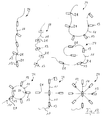
- lighters 13 with a common fuse 11 too connect. In any case, a single ignition of the end is sufficient 12 to activate all the lighters 13.
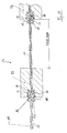
- the fuse 11 For example, as shown in Figs. 4 and 5, the igniter heads may be used 21 and igniter 13 penetrate. The further burn of the Fuse 11 is not by the ignition 21 and igniter 13 with special needs.
- the lighters 13 are as permanent protection against Moisture and against outgassing individually in combustible film 23rd packed up.
- the number of lighters 13 in the ignition device 24 is variable depending on the size of the fuel package 1. A Cutting the fuse 11 can individually the number of pretend associated lighter 13.
- the lighter 13 Essential for a reliable burning of the lighter 13 is the provision of at least one ignition accelerator 16, the between the fuse 11 and the actual lighter 13th is provided and causes the glowing fuse 11th cause a great heat to ignite the ignition head 21. With the ignition accelerator 16, the lighter 13 can also relatively far down in the coal pieces 2 are what their supports optimal burning and annealing. An additional one second firing head 21 on a lighter 13 provides increased Safety of his inflammation, even if he, for example was damaged during packing of the fuel package.
- An ignition accelerator 16 here comprises a mixture of Black powder and sulfur and is each in a radial of arranged the fuse 11 outwardly facing air duct 17. Their number is variable.
- a firing head 21 is shown, the addition to the outside with an auxiliary fuel 18th is provided. This includes, for example, wood chips or others elongated substances that continue the burning of the lighter 13 on secure and strengthen.
- the fuse 11 can from a Be surrounded by black powder coat 19.
- An outer cover As a thermal insulator, 22 offers additional safety for the User and is excluded in the ignition head 21, so that they sit directly on the black powder coat 19. By the recesses are the lighters 13 in their position on the Fuse 11 secured against slipping.
- a large area networked detonator in the form of a fuel paste 113 is provided.
- the alternative fuel package 101 according to FIGS. 6 and 7 has in principle similarity to the first embodiment a horizontal tear thread 108, which allows that the upper packaging part can be lifted off in the manner of a hood (Transition from Fig. 6 to Fig. 7).
- the subset 3 is similar here formed to the first embodiment, but with a over a large area distributed fuel paste as a lighter 113 in place single lighter 13 provided. Again, the fuse 11 initially held within the package 106 and can after their openings are led out. At the transition from the Fuse 11 to the fuel paste 113 is again at least one Firing head 21 is provided with ignition accelerator 16, the safe burning of the fuel paste 113 causes.
- the fuel paste 113 can also function as a bonding agent 10 in a dual function Pieces of coal 2 with each other or between pieces of coal 2 and serve the subset 3.
- the embodiment of the fuel package 201 after the Figures 8 and 9 are very similar to those just explained, only here changed the shape of the pedestal 203 and the packaging 206.
- the base 203 is rather plate-like flat, at least some of Coal pieces 2 are adhesively bonded together.
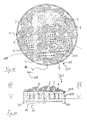
- FIG. 11 and 12 is another embodiment a round in plan view and relatively large fuel package 301 shown.
- the pedestal 303 has vertical side walls 305 with also recesses 9 and downwards feet 20 on which the air flow through the embers due to their Increase distance function to the ground.
Landscapes
- Engineering & Computer Science (AREA)
- Food Science & Technology (AREA)
- Solid Fuels And Fuel-Associated Substances (AREA)
- Lighters Containing Fuel (AREA)
- Organic Low-Molecular-Weight Compounds And Preparation Thereof (AREA)
- Control Of The Air-Fuel Ratio Of Carburetors (AREA)
Abstract
Description
- Fig. 1
- eine schematische Querschnittsansicht eines erfindungsgemäßen Brennstoffpakets im verpackten Zustand,
- Fig. 2
- das Brennstoffpaket nach Fig. 1 nach Entfernen der Verpackung und Herausführen der Zündschnur,
- Fig. 3
- eine Detailansicht des äußeren Zündschnurendes mit einer daran angehängten Reibefläche,
- Fig. 4
- einen Schnitt durch einen Festkörperanzünder mit Zündkopf und Entzündbeschleuniger an einem Ende,
- Fig. 5
- eine ähnliche Ansicht wie Fig. 4, jedoch mit zwei Zündköpfen und Entzündbeschleunigern an dem Festkörperanzünder,
- Fig. 6
- eine ähnliche Ansicht wie Fig. 1 eines alternativen Brennstoffpakets mit einem einzigen Anzünder durch eine Brennpaste,
- Fig. 7
- eine ähnliche Ansicht wie Fig. 6 nach Entfernen des Oberteils der Verpackung,
- Fig. 8
- eine ähnliche Ansicht wie Fig. 6 eines weiteren, prinzipiell ähnlichen Brennstoffpakets mit einem alternativ geformten Untersatz,
- Fig. 9
- eine ähnliche Ansicht wie Fig. 8 nach Entfernen des Oberteils der Verpackung,
- Fig. 10
- eine Detailansicht des Übergangsbereichs zwischen der Zündschnur und der Brennpaste in den Ausführungsbeispielen nach den Figuren 6 bis 9,
- Fig. 11
- eine ähnliche Ansicht wie Fig. 6 eines in Draufsicht runden, prinzipiell ähnlichen Brennstoffpakets mit einem alternativ geformten Untersatz,
- Fig. 12
- einen Schnitt entlang der Linie XII-XII in Fig. 11,
- Fig. 13
- unterschiedliche Anordnungen von Zündschnüren und Anzündern in schematischer Übersicht,
- Fig. 14
- eine Detailansicht des Zündschnurverlaufs und dadurch verbundener Anzünder in Fig. 13.
- 1, 101, 201, 301
- Brennstoffpaket,
- 2
- Kohlenstücke,
- 3, 203, 303
- Untersatz,
- 4
- Unterfläche,
- 5, 305
- Wandungen,
- 6, 106, 206
- Verpackung,
- 7
- Tragegriff,
- 8, 108
- Schnellverschluß,
- 9
- Ausnehmungen,
- 10
- Haftvermittler,
- 11
- Zündhilfe,
- 12
- deren äußeres Ende,
- 13, 113
- Anzünder,
- 14
- Anzündkopf,
- 15
- Reibefläche,
- 16,
- Entzündhilfe,
- 17
- Luftkanal,
- 18
- Hilfsbrennstoff,
- 19
- Schwarzpulvermantel,
- 20
- Standfüße,
- 21
- Zündkopf,
- 22
- Deckmantel,
- 23
- Umhüllung,
- 24
- Entzündvorrichtung
Claims (14)
- Formstabiles Brennstoffpaket (1;101;201;301) mit einer Vielzahl von auf einem Untersatz (3;203;303) angeordneten Kohlestücken (2) und einer umgreifenden Verpackung (6; 106; 206),
dadurch gekennzeichnet, daß der Untersatz (3;203;303) aus brennbarem Material besteht - Formstabiles Brennstoffpaket (1;101;201;301) mit einer Vielzahl von auf einem Untersatz (3;203;303) angeordneten Kohlestücken (2) und einer umgreifenden Verpackung (6; 106; 206), insbesondere nach Anspruch 1,
dadurch gekennzeichnet, daß das Brennstoffpaket (1;101;201;301) auch nach Entfernen der Verpackung (6) formstabil ist. - Brennstoffpaket (1;101;201;301) nach einem der Ansprüche 1 oder 2,
dadurch gekennzeichnet, daß Kohlestücke (2) mit dem Untersatz (3;203;303) haftend verbunden sind. - Brennstoffpaket (1;101;201;301) nach einem der Ansprüche 1 bis 3,
dadurch gekennzeichnet, daß der Untersatz (3;203;303) einen Teller oder eine Schale aus verpreßter Kohle bildet. - Brennstoffpaket (1;101;201;301) nach einem der Ansprüche 1 bis 4,
dadurch gekennzeichnet, daß der Untersatz (3;203;303) mit einem Muster von Ausnehmungen (9) versehen ist. - Brennstoffpaket (1;101;201;301) nach einem der Ansprüche 1 bis 5,
dadurch gekennzeichnet, daß dessen Außenkontur eine regelmäßige geometrische Form ausbildet. - Brennstoffpaket (1;101;201;301) nach Anspruch 6,
dadurch gekennzeichnet, daß die Verpackung (6;106;206) formstabil die geometrische Form abbildet. - Brennstoffpaket (1;101;201;301) nach einem der Ansprüche 1 bis 7,
dadurch gekennzeichnet, daß dieses zumindest einen integrierten Anzünder (13;113) umfaßt. - Brennstoffpaket (1;101;201;301) nach einem der Ansprüche 1 bis 8,
dadurch gekennzeichnet, daß die Haftung von Kohlestücken (2) untereinander bzw. mit dem Untersatz (3;203;303) durch einen brennbaren und als Anzünder (113) wirkenden Haftvermittler (10) bewirkt ist. - Brennstoffpaket (1;101;201;301) nach einem der Ansprüche 1 bis 9,
dadurch gekennzeichnet, daß dieses eine nach außen führbare Zündschnur oder dergleichen Zündhilfe (11) umfaßt. - Brennstoffpaket (1;101;201;301) nach Anspruch 10,
dadurch gekennzeichnet, daß die Zündschnur (11) mit einer Reibefläche (15) und einem daran entzündbaren Anzündkopf (14) versehen ist. - Entzündvorrichtung (24) für ein Brennstoffpaket (1;101;201; 301) mit einer Vielzahl von Kohle- oder Holzstücken (2), insbesondere für ein Brennstoffpaket nach einem der Ansprüche 1 bis 11,
dadurch gekennzeichnet, daß die Entzündvorrichtung (24) mehrere Festkörperanzünder (13) umfaßt, die jeweils mit der Zündschnur (11) verbunden sind, wobei der Zündschnur (11) und einem jeweiligen Anzünder (13) zumindest ein Zündkopf (21) mit einem oder mehreren Entzündbeschleuniger(n) (16) zwischengeordnet ist. - Entzündvorrichtung (24) nach Anspruch 12,
dadurch gekennzeichnet, daß diese bedarfsgerecht ablängbar ist. - Entzündvorrichtung (24) nach einem der Ansprüche 12 oder 13,
dadurch gekennzeichnet, daß die Festkörperanzünder (13) jeweils in einer brennbaren, den Durchtritt von Gas und Wasser hemmenden Umhüllung (23) gehalten sind.
Applications Claiming Priority (2)
| Application Number | Priority Date | Filing Date | Title |
|---|---|---|---|
| DE10360049 | 2003-12-22 | ||
| DE10360049 | 2003-12-22 |
Publications (2)
| Publication Number | Publication Date |
|---|---|
| EP1547500A1 true EP1547500A1 (de) | 2005-06-29 |
| EP1547500B1 EP1547500B1 (de) | 2010-03-17 |
Family
ID=34530339
Family Applications (1)
| Application Number | Title | Priority Date | Filing Date |
|---|---|---|---|
| EP04030373A Expired - Lifetime EP1547500B1 (de) | 2003-12-22 | 2004-12-21 | Brennstoffpaket |
Country Status (4)
| Country | Link |
|---|---|
| EP (1) | EP1547500B1 (de) |
| AT (1) | ATE460870T1 (de) |
| DE (1) | DE502004010903D1 (de) |
| PT (1) | PT1547500E (de) |
Cited By (2)
| Publication number | Priority date | Publication date | Assignee | Title |
|---|---|---|---|---|
| WO2008049100A3 (en) * | 2006-10-19 | 2008-07-10 | Sonoco Dev Inc | Combustible packages for containing a fuel source and a fire starter |
| WO2013017133A1 (en) * | 2011-08-01 | 2013-02-07 | Easyburn Aps | Combustible package for containing a fuel source |
Citations (6)
| Publication number | Priority date | Publication date | Assignee | Title |
|---|---|---|---|---|
| GB839602A (en) * | 1958-05-12 | 1960-06-29 | Diamond National Corp | A self-kindling fuel package for charcoal briquettes and the like |
| DE2646911A1 (de) * | 1976-10-18 | 1978-04-20 | Albrecht Bruno Kg | Grillkohlepackung mit integriertem anzuender |
| FR2620725A1 (fr) * | 1987-09-21 | 1989-03-24 | Genelot Bernard | Conditionnement de charbon de bois avec dispositif d'allumage de feu de barbecue ou de feu de cheminee |
| US4953533A (en) * | 1990-02-06 | 1990-09-04 | Witt Gary L | Self-igniting combustion package |
| EP0943276A1 (de) * | 1998-01-09 | 1999-09-22 | Kurt Fuchs | Anordnung zur Erzeugung einer Grillkohlenglut |
| US6328028B1 (en) * | 2000-04-12 | 2001-12-11 | Bcdc Enterprises | Self-contained charcoal product, and method |
-
2004
- 2004-12-21 AT AT04030373T patent/ATE460870T1/de not_active IP Right Cessation
- 2004-12-21 EP EP04030373A patent/EP1547500B1/de not_active Expired - Lifetime
- 2004-12-21 DE DE502004010903T patent/DE502004010903D1/de not_active Expired - Lifetime
- 2004-12-21 PT PT04030373T patent/PT1547500E/pt unknown
Patent Citations (6)
| Publication number | Priority date | Publication date | Assignee | Title |
|---|---|---|---|---|
| GB839602A (en) * | 1958-05-12 | 1960-06-29 | Diamond National Corp | A self-kindling fuel package for charcoal briquettes and the like |
| DE2646911A1 (de) * | 1976-10-18 | 1978-04-20 | Albrecht Bruno Kg | Grillkohlepackung mit integriertem anzuender |
| FR2620725A1 (fr) * | 1987-09-21 | 1989-03-24 | Genelot Bernard | Conditionnement de charbon de bois avec dispositif d'allumage de feu de barbecue ou de feu de cheminee |
| US4953533A (en) * | 1990-02-06 | 1990-09-04 | Witt Gary L | Self-igniting combustion package |
| EP0943276A1 (de) * | 1998-01-09 | 1999-09-22 | Kurt Fuchs | Anordnung zur Erzeugung einer Grillkohlenglut |
| US6328028B1 (en) * | 2000-04-12 | 2001-12-11 | Bcdc Enterprises | Self-contained charcoal product, and method |
Cited By (3)
| Publication number | Priority date | Publication date | Assignee | Title |
|---|---|---|---|---|
| WO2008049100A3 (en) * | 2006-10-19 | 2008-07-10 | Sonoco Dev Inc | Combustible packages for containing a fuel source and a fire starter |
| US7789919B2 (en) | 2006-10-19 | 2010-09-07 | Sonoco Development, Inc. | Combustible packages for containing a fuel source and a fire starter |
| WO2013017133A1 (en) * | 2011-08-01 | 2013-02-07 | Easyburn Aps | Combustible package for containing a fuel source |
Also Published As
| Publication number | Publication date |
|---|---|
| DE502004010903D1 (de) | 2010-04-29 |
| ATE460870T1 (de) | 2010-04-15 |
| EP1547500B1 (de) | 2010-03-17 |
| PT1547500E (pt) | 2010-06-16 |
Similar Documents
| Publication | Publication Date | Title |
|---|---|---|
| US4762525A (en) | Prepackaged firebox apparatus for outdoor cooking or the like | |
| US5226405A (en) | Ignition platform and fuel component for kindling a fire | |
| US3374071A (en) | Fire kindling devices | |
| US8597381B2 (en) | Compact fire log | |
| US20150322361A1 (en) | Fire Starting Apparatus and Method | |
| EP1992265A1 (de) | Brennstoffeinheit | |
| US3279900A (en) | Rapid ignition charcoal package and method of igniting | |
| US4179270A (en) | Aid for kindling fires | |
| US4782812A (en) | Meat grill | |
| DE29517488U1 (de) | Feueranzünder mit zwei Entflammungsniveaus | |
| DE2926540A1 (de) | Barbecue-vorrichtung | |
| US10602880B2 (en) | Fuel-containing fire-starting device | |
| EP1547500B1 (de) | Brennstoffpaket | |
| DE102020103807B3 (de) | Brenneinrichtung | |
| EP1930398A1 (de) | Feueranzünder, sowie Vorrichtung zum Anzünden eines Ofen-, Kamin- oder Grillfeuers und Verfahren zur Herstellung | |
| DE202017103482U1 (de) | Brennmaterialbehälter | |
| HUE032734T2 (en) | Self-igniting collector | |
| US11149225B1 (en) | Incendiary device | |
| DE60010670T2 (de) | Verbesserter anzündeklotz | |
| MXPA05000310A (es) | Un aparato para encender carbon. | |
| DE1532143A1 (de) | Selbstzuendende Zigarette | |
| DE20002328U1 (de) | Brennstoffpackung | |
| WO2016087410A1 (de) | Aufnahmebehälter für ein festbrennstoffelement | |
| DE102019121223B4 (de) | Kamin- oder Kaminofenbeschickvorrichtung | |
| DE202016100492U1 (de) | Vorrichtung zum Bereitstellen von Holzkohle für einen Grill |
Legal Events
| Date | Code | Title | Description |
|---|---|---|---|
| PUAI | Public reference made under article 153(3) epc to a published international application that has entered the european phase |
Free format text: ORIGINAL CODE: 0009012 |
|
| AK | Designated contracting states |
Kind code of ref document: A1 Designated state(s): AT BE BG CH CY CZ DE DK EE ES FI FR GB GR HU IE IS IT LI LT LU MC NL PL PT RO SE SI SK TR |
|
| AX | Request for extension of the european patent |
Extension state: AL BA HR LV MK YU |
|
| 17P | Request for examination filed |
Effective date: 20051227 |
|
| AKX | Designation fees paid |
Designated state(s): AT BE BG CH CY CZ DE DK EE ES FI FR GB GR HU IE IS IT LI LT LU MC NL PL PT RO SE SI SK TR |
|
| 17Q | First examination report despatched |
Effective date: 20070613 |
|
| GRAP | Despatch of communication of intention to grant a patent |
Free format text: ORIGINAL CODE: EPIDOSNIGR1 |
|
| GRAS | Grant fee paid |
Free format text: ORIGINAL CODE: EPIDOSNIGR3 |
|
| GRAA | (expected) grant |
Free format text: ORIGINAL CODE: 0009210 |
|
| AK | Designated contracting states |
Kind code of ref document: B1 Designated state(s): AT BE BG CH CY CZ DE DK EE ES FI FR GB GR HU IE IS IT LI LT LU MC NL PL PT RO SE SI SK TR |
|
| REG | Reference to a national code |
Ref country code: GB Ref legal event code: FG4D Free format text: NOT ENGLISH |
|
| REG | Reference to a national code |
Ref country code: CH Ref legal event code: EP |
|
| REG | Reference to a national code |
Ref country code: IE Ref legal event code: FG4D |
|
| REF | Corresponds to: |
Ref document number: 502004010903 Country of ref document: DE Date of ref document: 20100429 Kind code of ref document: P |
|
| REG | Reference to a national code |
Ref country code: PT Ref legal event code: SC4A Free format text: AVAILABILITY OF NATIONAL TRANSLATION Effective date: 20100608 Ref country code: NL Ref legal event code: T3 |
|
| REG | Reference to a national code |
Ref country code: GR Ref legal event code: EP Ref document number: 20100401370 Country of ref document: GR |
|
| PG25 | Lapsed in a contracting state [announced via postgrant information from national office to epo] |
Ref country code: LT Free format text: LAPSE BECAUSE OF FAILURE TO SUBMIT A TRANSLATION OF THE DESCRIPTION OR TO PAY THE FEE WITHIN THE PRESCRIBED TIME-LIMIT Effective date: 20100317 |
|
| LTIE | Lt: invalidation of european patent or patent extension |
Effective date: 20100317 |
|
| PG25 | Lapsed in a contracting state [announced via postgrant information from national office to epo] |
Ref country code: SI Free format text: LAPSE BECAUSE OF FAILURE TO SUBMIT A TRANSLATION OF THE DESCRIPTION OR TO PAY THE FEE WITHIN THE PRESCRIBED TIME-LIMIT Effective date: 20100317 Ref country code: PL Free format text: LAPSE BECAUSE OF FAILURE TO SUBMIT A TRANSLATION OF THE DESCRIPTION OR TO PAY THE FEE WITHIN THE PRESCRIBED TIME-LIMIT Effective date: 20100317 Ref country code: FI Free format text: LAPSE BECAUSE OF FAILURE TO SUBMIT A TRANSLATION OF THE DESCRIPTION OR TO PAY THE FEE WITHIN THE PRESCRIBED TIME-LIMIT Effective date: 20100317 |
|
| REG | Reference to a national code |
Ref country code: IE Ref legal event code: FD4D |
|
| PG25 | Lapsed in a contracting state [announced via postgrant information from national office to epo] |
Ref country code: CY Free format text: LAPSE BECAUSE OF FAILURE TO SUBMIT A TRANSLATION OF THE DESCRIPTION OR TO PAY THE FEE WITHIN THE PRESCRIBED TIME-LIMIT Effective date: 20100317 Ref country code: ES Free format text: LAPSE BECAUSE OF FAILURE TO SUBMIT A TRANSLATION OF THE DESCRIPTION OR TO PAY THE FEE WITHIN THE PRESCRIBED TIME-LIMIT Effective date: 20100628 Ref country code: EE Free format text: LAPSE BECAUSE OF FAILURE TO SUBMIT A TRANSLATION OF THE DESCRIPTION OR TO PAY THE FEE WITHIN THE PRESCRIBED TIME-LIMIT Effective date: 20100317 Ref country code: SE Free format text: LAPSE BECAUSE OF FAILURE TO SUBMIT A TRANSLATION OF THE DESCRIPTION OR TO PAY THE FEE WITHIN THE PRESCRIBED TIME-LIMIT Effective date: 20100317 Ref country code: RO Free format text: LAPSE BECAUSE OF FAILURE TO SUBMIT A TRANSLATION OF THE DESCRIPTION OR TO PAY THE FEE WITHIN THE PRESCRIBED TIME-LIMIT Effective date: 20100317 |
|
| PG25 | Lapsed in a contracting state [announced via postgrant information from national office to epo] |
Ref country code: BG Free format text: LAPSE BECAUSE OF FAILURE TO SUBMIT A TRANSLATION OF THE DESCRIPTION OR TO PAY THE FEE WITHIN THE PRESCRIBED TIME-LIMIT Effective date: 20100617 Ref country code: CZ Free format text: LAPSE BECAUSE OF FAILURE TO SUBMIT A TRANSLATION OF THE DESCRIPTION OR TO PAY THE FEE WITHIN THE PRESCRIBED TIME-LIMIT Effective date: 20100317 Ref country code: IS Free format text: LAPSE BECAUSE OF FAILURE TO SUBMIT A TRANSLATION OF THE DESCRIPTION OR TO PAY THE FEE WITHIN THE PRESCRIBED TIME-LIMIT Effective date: 20100717 Ref country code: SK Free format text: LAPSE BECAUSE OF FAILURE TO SUBMIT A TRANSLATION OF THE DESCRIPTION OR TO PAY THE FEE WITHIN THE PRESCRIBED TIME-LIMIT Effective date: 20100317 |
|
| PLBE | No opposition filed within time limit |
Free format text: ORIGINAL CODE: 0009261 |
|
| STAA | Information on the status of an ep patent application or granted ep patent |
Free format text: STATUS: NO OPPOSITION FILED WITHIN TIME LIMIT |
|
| PG25 | Lapsed in a contracting state [announced via postgrant information from national office to epo] |
Ref country code: DK Free format text: LAPSE BECAUSE OF FAILURE TO SUBMIT A TRANSLATION OF THE DESCRIPTION OR TO PAY THE FEE WITHIN THE PRESCRIBED TIME-LIMIT Effective date: 20100317 Ref country code: IE Free format text: LAPSE BECAUSE OF FAILURE TO SUBMIT A TRANSLATION OF THE DESCRIPTION OR TO PAY THE FEE WITHIN THE PRESCRIBED TIME-LIMIT Effective date: 20100317 |
|
| 26N | No opposition filed |
Effective date: 20101220 |
|
| BERE | Be: lapsed |
Owner name: WECKERMANN, ANDREAS Effective date: 20101231 |
|
| PG25 | Lapsed in a contracting state [announced via postgrant information from national office to epo] |
Ref country code: MC Free format text: LAPSE BECAUSE OF NON-PAYMENT OF DUE FEES Effective date: 20101231 |
|
| REG | Reference to a national code |
Ref country code: CH Ref legal event code: PL |
|
| PG25 | Lapsed in a contracting state [announced via postgrant information from national office to epo] |
Ref country code: BE Free format text: LAPSE BECAUSE OF NON-PAYMENT OF DUE FEES Effective date: 20101231 |
|
| PG25 | Lapsed in a contracting state [announced via postgrant information from national office to epo] |
Ref country code: LI Free format text: LAPSE BECAUSE OF NON-PAYMENT OF DUE FEES Effective date: 20101231 Ref country code: CH Free format text: LAPSE BECAUSE OF NON-PAYMENT OF DUE FEES Effective date: 20101231 |
|
| PG25 | Lapsed in a contracting state [announced via postgrant information from national office to epo] |
Ref country code: IT Free format text: LAPSE BECAUSE OF NON-PAYMENT OF DUE FEES Effective date: 20101221 |
|
| PG25 | Lapsed in a contracting state [announced via postgrant information from national office to epo] |
Ref country code: AT Free format text: LAPSE BECAUSE OF NON-PAYMENT OF DUE FEES Effective date: 20101221 |
|
| REG | Reference to a national code |
Ref country code: AT Ref legal event code: MM01 Ref document number: 460870 Country of ref document: AT Kind code of ref document: T Effective date: 20101221 |
|
| PG25 | Lapsed in a contracting state [announced via postgrant information from national office to epo] |
Ref country code: HU Free format text: LAPSE BECAUSE OF FAILURE TO SUBMIT A TRANSLATION OF THE DESCRIPTION OR TO PAY THE FEE WITHIN THE PRESCRIBED TIME-LIMIT Effective date: 20100918 Ref country code: LU Free format text: LAPSE BECAUSE OF NON-PAYMENT OF DUE FEES Effective date: 20101221 |
|
| PG25 | Lapsed in a contracting state [announced via postgrant information from national office to epo] |
Ref country code: TR Free format text: LAPSE BECAUSE OF FAILURE TO SUBMIT A TRANSLATION OF THE DESCRIPTION OR TO PAY THE FEE WITHIN THE PRESCRIBED TIME-LIMIT Effective date: 20100317 |
|
| PGFP | Annual fee paid to national office [announced via postgrant information from national office to epo] |
Ref country code: IT Payment date: 20141212 Year of fee payment: 11 |
|
| REG | Reference to a national code |
Ref country code: FR Ref legal event code: PLFP Year of fee payment: 12 |
|
| REG | Reference to a national code |
Ref country code: FR Ref legal event code: PLFP Year of fee payment: 13 |
|
| PG25 | Lapsed in a contracting state [announced via postgrant information from national office to epo] |
Ref country code: IT Free format text: LAPSE BECAUSE OF NON-PAYMENT OF DUE FEES Effective date: 20151221 |
|
| PGFP | Annual fee paid to national office [announced via postgrant information from national office to epo] |
Ref country code: GB Payment date: 20161212 Year of fee payment: 13 Ref country code: FR Payment date: 20161129 Year of fee payment: 13 |
|
| PGFP | Annual fee paid to national office [announced via postgrant information from national office to epo] |
Ref country code: PT Payment date: 20161209 Year of fee payment: 13 Ref country code: GR Payment date: 20161125 Year of fee payment: 13 |
|
| PGFP | Annual fee paid to national office [announced via postgrant information from national office to epo] |
Ref country code: NL Payment date: 20171023 Year of fee payment: 14 |
|
| PGFP | Annual fee paid to national office [announced via postgrant information from national office to epo] |
Ref country code: DE Payment date: 20171231 Year of fee payment: 14 |
|
| PG25 | Lapsed in a contracting state [announced via postgrant information from national office to epo] |
Ref country code: PT Free format text: LAPSE BECAUSE OF NON-PAYMENT OF DUE FEES Effective date: 20180621 |
|
| GBPC | Gb: european patent ceased through non-payment of renewal fee |
Effective date: 20171221 |
|
| REG | Reference to a national code |
Ref country code: FR Ref legal event code: ST Effective date: 20180831 |
|
| PG25 | Lapsed in a contracting state [announced via postgrant information from national office to epo] |
Ref country code: FR Free format text: LAPSE BECAUSE OF NON-PAYMENT OF DUE FEES Effective date: 20180102 |
|
| PG25 | Lapsed in a contracting state [announced via postgrant information from national office to epo] |
Ref country code: GB Free format text: LAPSE BECAUSE OF NON-PAYMENT OF DUE FEES Effective date: 20171221 Ref country code: GR Free format text: LAPSE BECAUSE OF NON-PAYMENT OF DUE FEES Effective date: 20180705 |
|
| REG | Reference to a national code |
Ref country code: DE Ref legal event code: R119 Ref document number: 502004010903 Country of ref document: DE |
|
| REG | Reference to a national code |
Ref country code: NL Ref legal event code: MM Effective date: 20190101 |
|
| PG25 | Lapsed in a contracting state [announced via postgrant information from national office to epo] |
Ref country code: NL Free format text: LAPSE BECAUSE OF NON-PAYMENT OF DUE FEES Effective date: 20190101 |
|
| PG25 | Lapsed in a contracting state [announced via postgrant information from national office to epo] |
Ref country code: DE Free format text: LAPSE BECAUSE OF NON-PAYMENT OF DUE FEES Effective date: 20190702 |