EP1547455B1 - Groupe frigorifique plat a refrigeration a contre-courant - Google Patents
Groupe frigorifique plat a refrigeration a contre-courant Download PDFInfo
- Publication number
- EP1547455B1 EP1547455B1 EP03750305A EP03750305A EP1547455B1 EP 1547455 B1 EP1547455 B1 EP 1547455B1 EP 03750305 A EP03750305 A EP 03750305A EP 03750305 A EP03750305 A EP 03750305A EP 1547455 B1 EP1547455 B1 EP 1547455B1
- Authority
- EP
- European Patent Office
- Prior art keywords
- air
- cooling
- region
- cooling unit
- chambers
- Prior art date
- Legal status (The legal status is an assumption and is not a legal conclusion. Google has not performed a legal analysis and makes no representation as to the accuracy of the status listed.)
- Expired - Lifetime
Links
Images


Classifications
-
- H—ELECTRICITY
- H05—ELECTRIC TECHNIQUES NOT OTHERWISE PROVIDED FOR
- H05K—PRINTED CIRCUITS; CASINGS OR CONSTRUCTIONAL DETAILS OF ELECTRIC APPARATUS; MANUFACTURE OF ASSEMBLAGES OF ELECTRICAL COMPONENTS
- H05K7/00—Constructional details common to different types of electric apparatus
- H05K7/20—Modifications to facilitate cooling, ventilating, or heating
- H05K7/20536—Modifications to facilitate cooling, ventilating, or heating for racks or cabinets of standardised dimensions, e.g. electronic racks for aircraft or telecommunication equipment
- H05K7/206—Air circulating in closed loop within cabinets wherein heat is removed through air-to-air heat-exchanger
Definitions
- the invention relates to a flat cooling unit for use as a heat exchanger in the cooling of air from, for example, a cabinet, a server cabinet or a cabinet in which are installed heat generating devices whose heat is dissipated from the substantially closed housing assembly to an internal temperature these housing arrangements do not rise above a predetermined maximum value.
- Heat exchangers in the sense of a countercurrent principle, in which cooling air flows in one direction and flows in separate flow chambers, the air to be cooled in the other direction, are already attributable to the prior art, see. for example DE-A 30 44 135 (Siemens). There, a heat exchanger with flow channels is described, which are oriented with its cross section substantially perpendicular to the flat side of the heat exchanger and run longitudinally, see. Figure 2 there and with respect to the countercurrent principle the local column 6, lines 10 to 20.
- a non-countercurrent exchanger arrangement is described, for example, in DE-A 198 04 904 (Rittal), where specific places in the interior, which are subject to increased heat output, can be cooled separately with hoses, these cooling hoses easily adapted to different conditions of the interior (see there the only figure and column 1, lines 54 to 58.)
- a double-walled wall element on the cabinet (rear) side ensures the heat exchange, although no countercurrent principle is used.
- the invention has set itself the task of further increasing the performance of Jacobüngs heat exchangers, the heat loss is so from the housing or possibly a device that has cabinet size, to be dissipated, that a smaller increase in the internal temperature per watt dissipated power loss in housing or cabinet (° K per watt or W / ° K).
- Claim 14 may be the operation of claim 1, Cf. claim 19.
- the air in the inner circle and in the outer circle is guided exactly in countercurrent. This achieves maximum effectiveness.
- axial fans are used, whose performance is much higher (claim 3) and also provide fewer deflections for the moving (flowing) air.
- the axially drawn in air is also discharged axially and pressed in the inlet region in the counterflow heat exchanger, while at the outlet region also such an axial fan - spaced from the input area - can be arranged, which then extracts the cooled air from the heat exchanger and back into the control cabinet, Server cabinet or equipment cabinet or a single large device brings in (claim 1, 14).
- the fan at the inlet area should be operated at a higher power, be operable or operated at a higher speed than that at the outlet area.
- the cooling air provided by also two axial countercurrent fans it is preferable that these two fans have substantially the same capacity, speed or power setting at the inlet portion of the cooling air and the outlet portion of the cooling air (the exhaust air).
- the flow path of the cooling air is practically rectilinear (claim 1). Between the output of the first fan and the second fan, the path of the cooling air is practically straight through the chambers, only interrupted by the inflow and outflow of the air to be cooled, which is in no physical contact with the cooling air, but by separate chambers in the
- the U-shaped design of the flow path for the air to be cooled has proven to be favorable in so far as this air experiences as few deflections during its flow path, the axial fans make a contribution.
- air is forced into a first stagnation chamber, which is under positive pressure by the action of the first fan.
- the air is distributed to a plurality of parallel surface chambers, which extend flat parallel to the flat side of the heat exchanger.
- the cooled air from the individual, parallel and spaced surface chambers collects again in a substantially cylindrical collecting space, from which they are cooled in the air Area is returned, in which the heat is generated.
- another (referred to in the claims as the fourth fan) axial fan can be arranged, which withdraws the air from the plenum, but preferably with a lower power than that first fan, which introduces the air in the first storage space (claims 11 , 12.18).
- a turbulent, swirling flow preferably with an on the surface not flat plates (claim 6) provides increased heat exchanger performance.
- the flow chambers designated as two-dimensional chambers for the air to be cooled and also for the cooling air have only a small height relative to their width and length. Width and height is to be understood here that these two dimensions describe a plane parallel to the flat side of the heat exchanger, while the height in the direction of the thickness, that is defined perpendicular to the flat extent of the flat cooling unit (claims 16, 17).
- the exchanger performance is also increased by the fact that the countercurrent exchange does not take place only after the inlet and up to the outlet of the air to be cooled, but also beyond, ie downstream of the outlet and upstream of the inlet (claim 15).
- the air to be cooled is described as the air which is circulated as domestic air within the cabinet system and thereby cooled. It has at its outlet the lowest possible temperature and is referred to here as cooled air, but often also - to represent the cycle - in the course of their overall course as air to be cooled.
- the useful air, with which the heat exchanger is cooled is referred to as cooling air, which is called in the outlet, where it has its maximum temperature, as exhaust air. Nevertheless, the cooling air remains named as such during its entire flow path in the exchanger in order to obtain a mutually consistent terminology for the invention to be described.
- the cooling air When the cooling air still flows past the inlet portion of the air to be cooled and the cooling air flows before the outlet portion (claim 15), it is provided in the regions of the inlet and outlet (the air to be cooled) so as to be on a width, which is not less than that width, in particular the diameter, of the inflow region or of the outflow region itself.
- a further increase in the cooling capacity or the heat output in the heat exchanger can be achieved with locking pieces (claim 7), which block a direct (short) flow path for the air to be cooled and distract this air to favor a turbulence or a turbulent flow from the shortest flow path and in force a longer flow path.
- These locking pieces may be formed as elbows, in particular adjustable (claim 8,9). They are arranged in the inlet area and in the outlet area, preferably opposite each other.
- the invention achieves, as far as possible, the countercurrent flow performance with as few right-angled deflections, while making full use of the available chambers as evenly as possible.
- a heat exchanger achieved more than twice as large cooling capacity, as currently available air heat exchangers in countercurrent principle. Values of above 400 W / ° K were achieved, which was achieved with a size of the heat exchanger with external dimensions of 100 cm length, 40 cm width and 18 cm height (thickness / thickness).
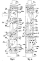
- Figure 1 illustrates a plan view of the flat side 51 of the flat cooling unit.
- two recesses 13, 23 are provided, which are aligned substantially along a center plane A, but have a significant distance in the direction of length I of the flat cooling unit. They are each arranged at a distance I 23 , I 13 of their respective centers of the upper and lower front end of the flat cooling unit in the front flat side 51.
- the recesses 23, 13 are circular and in cross-section along the plane A cylindrical spaces extend into the depth h of the cooling unit, see. FIG . 2 .
- the width of the cooling unit extends perpendicular to the length and is designated b in Figure 1.
- the heat sink is much longer than it is wide.
- the depth (thickness or thickness) in the direction h is again much smaller than the width. However, the depth can also be significantly increased if several of the sheet metal walls 50a, 50b, 50c to be described later are used to define the flow chambers k1, k2, k3,.
- the storage space 11 behind the inlet 13 and the collecting space 21 in front of the outlet 23 respectively cylindrical. These areas are also referred to as entry area and exit area.
- a first axial fan 10 is arranged, which pushes the warm air SL (suction air) to be cooled into the first stowage chamber 11 in an air flow.
- a second fan 20 may be disposed at the exit port 23 to provide cooled air receive the collection chamber 21 and return as compressed air DL in the circuit.
- the flat side 51 of Figure 1 is mounted as one or to a wall of a cabinet enclosure, such as a device cabinet, a server cabinet or a cabinet with corresponding openings, such as the door, a side wall or the rear wall.
- a cabinet enclosure such as a device cabinet, a server cabinet or a cabinet with corresponding openings, such as the door, a side wall or the rear wall.
- the openings 13, 23 access to the interior of the cabinet, which may be closed otherwise and will usually be closed. It then creates a circulation of the warm air volume in the cabinet through the heat exchanger, which in turn causes a cooling of the circulated cabinet air by cooling air KL countercurrent principle, which cooling air exits as exhaust air AL at the opposite end again.
- the airflow for cooling is schematically illustrated by arrows in FIG. It is supported by two input fans 30, 31 shown here, which are arranged adjacent and electrically connected in parallel. Also arranged adjacent and electrically also connected in parallel are two outlet fans 40, 41, all fan according to the principle of axial ventilation, ie with a rotation axis and an inner support, are arranged on the radial wings, which compress and promote the air. Air enters axially and axially, with the end of the inlet fans 30, 31 defining the beginning of the heat exchanger and the beginning of the outlet fans 40, 41 the end of the heat exchanger.
- the openings 13, 23 are arranged at a distance from the lower end and the upper end, they also have a distance b1, b2 and b3, b4 from the lateral longitudinal sides (narrow sides) of the heat exchanger.
- the inflow region 13 and the outflow region 23 are thus placed in the heat exchanger so that - seen in the flow direction of the cooling air KL - an exchanger surface is also found in front of the outlet region 23 and after the inlet region 13.
- Also next to the outlet area and adjacent to the inlet area exchanger surfaces are provided, so that a flushing of the here cylindrically shaped collection chamber or storage chamber 21, 11 is possible.
- the flow widths b1, b2 and b3, b4 should in each case taken together at least on the order of the diameter d13 and d23 of the opening 13, 23rd lie, but may preferably be made larger.
- the number of axial fans 30, 31, 40, 41 on the input end face and the output end face of the flat cooling unit depends on its dimensions. It can also be connected in parallel more axial fans, as well as less.
- This orientation of the flow chambers illustrate the two sections along the planes A and B, the section along the plane A illustrating the stagnation chamber and the collection chamber 11, 21, while the sectional view of Figure 3 along the plane B illustrates the entire flow path on which it can be seen that the webs 32 and the webs 42 in each case seal the same chamber on the front side (towards the outside).
- These two-dimensional flow chambers k1, k3, k5, k7 are those flow chambers (with odd indices) which receive the upwardly flowing, to be cooled hot air L3.
- the flow chambers k2, k4, k6, k8 which are in connection with the outside air in FIG. 3 are those flow chambers which receive the cooling outside air L4 and lead in countercurrent to the air flow L3 in the other chambers with the odd k indices. They are not closed at the end faces with webs, but in the areas of the inflow 13 and the outflow 23 for the (heated) air to be cooled.
- the webs 22a, 22b, 22c formed here (22 for short) and 12a, 12b, 12c (12 for short) seal the flow spaces of the outside air against the inside air tightly. These webs are schematically visible in the plan view of Figure 1 around the inlet 13 and around the outlet 23 around. They provide as well as the webs 32, 42 for a physical Separation of the elongated, flat flow chambers that carry the outside air and those other parallel flow chambers, which carry the indoor air.
- each flow chamber between the front, longitudinal sides 52, the front narrow sides 32, 42 and the webs 12 and 22 extends around inlet and outlet area.
- the areal extent of the chambers is thus substantially greater in their width and longitudinal direction than the height h of each of the chambers, the height being indicated by h1 for the chamber k1 and the height h2 for the chamber k2 in FIG.
- the other heights of the other chambers are corresponding.
- All chambers have the same web height practically the same height (thickness or thickness) with individual sheet metal layers 50a, 50b, 50c each of the chambers areally limited.
- the sheet metal layers may additionally be made uneven perpendicular to their extension, for example by corrugation or embossed knobs to increase the heat exchange surface between the chambers. But they are impermeable to the flow of air to physically separate the cooling air from the air to be cooled.
- the chamber heights were less than 10 mm, preferably less than 5 mm.
- the webs 12, 42 and 22, 32 are glued in the example with the sheets 50a, 50b, 50c, etc., in order to achieve an airtight seal.
- the stacked webs 52 may be glued in the frontal longitudinal region with the sheets in the edge region, in addition also be reinforced by a screw fastening.
- a respective arcuate cover plate 18, 28 is added as a flow barrier. It can extend completely into the depth of the storage space 11 and into the depth of the collecting space 21.
- the heat exchanger of Figure 4 in the plane B is formed as described with reference to Figures 1 to 3.
- a sectional view of the heat exchanger of Figure 4 would correspond exactly to that sectional view of Figure 3, with the same countercurrent principle and the same chamber height of the flat flow chambers.
- the vote of the electrical performance of the fan, or their sizes or their actually operated speed should preferably be such that the fan 10 is operated at a greater power than the fan 20.
- the stowage chamber 11 is replaced by a greater pressure than he can be reduced from the collection chamber 21 by the negative pressure.
- this technical design or this technical operation of the heat exchanger provide greater turbulence and increase the turbulence effect in the flat flow chambers.
- Different measures for changing the performance of the lower fan are alternatively possible. Different fan types (by size) can be used with regard to fans 10 or 20. It is possible to use the same fans, which are operated differently, and it is possible to use different fans, which are operated differently, but according to the same described specification.
- the fans 30, 31 and 40, 41 should be substantially the same, ie achieve the same air throughput.
- the cooling effects achieved with the arrangement described could be increased by 20% to 30% if the deflection surface or guide surface in the sense of locking pieces 18, 28 was added to the embodiment of FIG. 1, which is already outstanding in heat exchange performance.
- the residence time of the air to be cooled in the elongated flat chambers is achieved in addition to increasing the turbulence.
- the shortest path ie the short circuit for the guided in the U-shaped flow of movement air SL, L3, DL is blocked and despite maintaining the substantially U-shaped flow direction, the lateral sections b3, b4, b1, b2 next to the inflow opening 13 and next the outflow opening 23 participates in the heat exchange, which also applies to the front section I 23 and the rear section I 13 of the heat exchanger, based on the flow direction of the outer cooling air KL, AL.
- the external cooling air can exert its cooling effect ..
- a flushing of the The circulation can be affected when the arcuate locking pieces 18, 28 are adjusted, which adjustment can be oriented both in the circumferential direction, as well as in the axial direction by pushing in and out of the cylindrical storage chamber 11 and the cylindrical receiving chamber 21.
- the shape of the chambers 11, 21 is not limited to a cylindrical shape, but also in the immediate vicinity deviating geometries can be selected, such as ellipses and Peecke. But it is advantageous if the chamber extends to the very depth of the heat exchanger and occupy the entire height h of the flat cooling unit.
Landscapes
- Engineering & Computer Science (AREA)
- Aviation & Aerospace Engineering (AREA)
- Physics & Mathematics (AREA)
- Thermal Sciences (AREA)
- Microelectronics & Electronic Packaging (AREA)
- Cooling Or The Like Of Electrical Apparatus (AREA)
- Heat-Exchange Devices With Radiators And Conduit Assemblies (AREA)
- Medicines Containing Plant Substances (AREA)
- Vaporization, Distillation, Condensation, Sublimation, And Cold Traps (AREA)
Claims (19)
- Refroidisseur à surface plate destiné à être utilisé pour des armoires d'appareillage, des armoires de serveurs ou des armoires de commande ou un ensemble boîtier essentiellement fermé pour accueillir des dispositifs générateurs de chaleur, dans lequel la température de l'air réchauffé (SL) peut être abaissée à contre-courant (L4 ; L3 ; k1 ; k2...) avec de l'air réfrigéré (KL) circulant en sens inverse sans que l'air réfrigéré n'entre physiquement en contact avec le flux d'air (L1, L3, L5) réchauffé à réfrigérer dans le refroidisseur à surface plate, caractérisé en ce que,(a) des éléments de séparation étanches (12a, 12b, 12c ; 22a, 22b, 22c) sont prévus dans une zone d'admission (13, 11) et / ou dans une zone d'évacuation (23, 21) de l'air à réfrigérer, éléments à l'aide desquels des premiers canaux (k1, k3, k5) pour l'air à réfrigérer (L3) sont séparés de seconds canaux (k2, k4, k6) pour l'air réfrigérant (L4) ;(b) les éléments de séparation étanches (12a, 22a,...) de l'air à réfrigérer (L3) et de l'air réfrigérant (L4) de la zone d'admission (11) ou de la zone d'évacuation (21) sont disposés dans le refroidisseur et peuvent être entièrement exposés au flux d'air réfrigérant et d'air à réfrigérer, une surface d'échange étant ainsi également prévue avant la zone d'admission et après la zone d'évacuation.
- Refroidisseur selon la revendication précédente, dans lequel des entretoises pour la fermeture d'une chambre correspondante sont disposées de manière à ce qu'elles ferment de façon étanche des chambres à surface plate pour l'air à réfrigérer au niveau d'une face d'admission (30) et d'une face d'évacuation (40) de l'air réfrigéré et ferment de façon étanche les chambres à surface plate pour l'air réfrigéré (KL, L4, AL) au niveau de la zone d'admission et de la zone d'évacuation de l'air à réfrigérer (11, 21).
- Refroidisseur selon l'une des revendications précédentes, dans lequel deux ventilateurs (30, 31 ; 40, 41, 10) servent de ventilateurs axiaux.
- Refroidisseur selon l'une des revendications 2 ou 3, dans lequel les chambres (k1, k2, k3, k4) sont séparées les unes des autres par des tôles (50a, 50b, 50c, ...) et où les hauteurs (h1, h2,...) des chambres sont déterminées par l'écart entre les tôles.
- Refroidisseur selon l'une des revendications précédentes, dans lequel sont prévues des entretoises (12, 42, 22, 32) au niveau de la zone d'admission et de la zone d'évacuation (13, 23) aussi bien de l'air réfrigérant que de l'air à réfrigérer, ces entretoises étant disposées entre les tôles (50a, 50b) délimitant la surface plate des chambres et servant à la fermeture étanche de la chambre non ouverte à l'endroit correspondant.
- Refroidisseur selon la revendication 4 ou 5, dans lequel, les tôles ne sont pas planes mais sont plus particulièrement ondulées ou noppées.
- Refroidisseur selon l'une des revendications précédentes, dans lequel dans la zone d'admission de l'air à réfrigérer (SL) et / ou dans la zone d'évacuation de l'air réfrigéré (DL) sont prévus des éléments de blocage (28, 18) afin de bloquer une voie directe de circulation du flux entre la zone d'admission et la zone d'évacuation et de prolonger le cheminement de l'air à réfrigérer dans les chambres.
- Refroidisseur selon la revendication 7, dans lequel les éléments de blocage (18, 28) sont ajustables.
- Refroidisseur selon la revendication 7 ou 8, dans lequel les éléments de blocage sont de forme courbée.
- Refroidisseur selon l'une des revendications précédentes, dans lequel la zone d'admission (13, 11) et/ou la zone d'évacuation (23, 21) sont essentiellement de conception circulaire ou essentiellement de conception cylindrique dans une extension en hauteur (h) du refroidisseur.
- Refroidisseur selon l'une des revendications précédentes, dans lequel un troisième ventilateur (10) peut être mis en service au niveau de la zone d'admission (13, 11) de l'air à réfrigérer (SL) avec une vitesse de rotation qui est supérieure à la vitesse de rotation d'un quatrième ventilateur (20) au niveau de la zone d'évacuation de l'air réfrigéré (DL, 23), en particulier de plus de 10 % supérieure à la puissance du quatrième ventilateur (20).
- Refroidisseur selon l'une des revendications 1 à 10, dans lequel un quatrième ventilateur est disposé au niveau de la zone d'évacuation (21, 23) de l'air réfrigéré et dont la puissance est inférieure à celle d'un troisième ventilateur (10).
- Refroidisseur selon la revendication 4, dans lequel l'écart entre les tôles est déterminé par des entretoises (12a, 42a, 22a, 32a) et dans lequel la hauteur (h1, h2) de chaque chambre correspond à la hauteur des entretoises.
- Procédé de réfrigération d'air d'une armoire d'appareillage, d'une armoire de serveur ou d'une armoire de commande ou d'un ensemble boîtier essentiellement fermé pour accueillir des dispositifs générateurs de chaleur, dans lequel la température de l'air réchauffé (SL) est abaissée à contre-courant (L4 ; L3 ; k1; k2...) avec de l'air réfrigéré (KL) circulant en sens inverse sans que l'air réfrigéré n'entre physiquement en contact avec le flux d'air (L1, L3, L5) réchauffé à réfrigérer, caractérisé en ce que l'air réfrigéré (KL, AL) circule en passant devant une zone d'admission cylindrique (13, 11) pour le flux d'air à réfrigérer (SL, L1) et / ou avant une zone d'évacuation cylindrique (21, 23) pour le flux d'air déjà réfrigéré (L5, DL) avant et après l'admission / l'évacuation, afin de disposer d'une surface d'échange après ou avant l'admission ou l'évacuation.
- Procédé selon la revendication 14, dans lequel le passage du flux devant la zone d'admission ou la circulation du flux avant la zone d'évacuation se déroule sur une largeur (b1+b2 ; b3+b4) qui n'est pas inférieure et en particulier qui est essentiellement identique ou supérieure à une largeur, plus précisément à un diamètre (d13, d23) de la zone d'admission (13) ou de la zone d'évacuation (23) du flux.
- Procédé selon la revendication 14, dans lequel l'air à réfrigérer et l'air réfrigérant (L3, L4) circulent dans des couches à surface plate étendue dont la hauteur (h1, h2) est telle qu'elle favorise une circulation turbulente du flux dans les couches.
- Procédé selon la revendication 16, dans lequel les couches ont une hauteur inférieure à 10 mm, et en particulier inférieure à 5 mm.
- Procédé selon la revendication 14, dans lequel l'air réchauffé (SL) introduit à l'aide d'un troisième ventilateur (10) est introduit de façon plus intense, plus précisément avec une puissance plus importante que l'air d'un quatrième ventilateur (20) qui évacue l'air réfrigéré dans le refroidisseur dans la zone d'évacuation (23, 21) hors du refroidisseur.
- Procédé selon la revendication 14, dans lequel un refroidisseur selon la revendication 6 est utilisé.
Applications Claiming Priority (3)
| Application Number | Priority Date | Filing Date | Title |
|---|---|---|---|
| DE10240419A DE10240419B3 (de) | 2002-09-02 | 2002-09-02 | Flächiges Kühlaggregat im Gegenstromprinzip |
| DE10240419 | 2002-09-02 | ||
| PCT/DE2003/002904 WO2004023856A1 (fr) | 2002-09-02 | 2003-09-02 | Groupe frigorifique plat a refrigeration a contre-courant |
Publications (2)
| Publication Number | Publication Date |
|---|---|
| EP1547455A1 EP1547455A1 (fr) | 2005-06-29 |
| EP1547455B1 true EP1547455B1 (fr) | 2006-11-22 |
Family
ID=31969019
Family Applications (1)
| Application Number | Title | Priority Date | Filing Date |
|---|---|---|---|
| EP03750305A Expired - Lifetime EP1547455B1 (fr) | 2002-09-02 | 2003-09-02 | Groupe frigorifique plat a refrigeration a contre-courant |
Country Status (5)
| Country | Link |
|---|---|
| US (1) | US20060144070A1 (fr) |
| EP (1) | EP1547455B1 (fr) |
| AT (1) | ATE346485T1 (fr) |
| DE (3) | DE10240419B3 (fr) |
| WO (1) | WO2004023856A1 (fr) |
Families Citing this family (8)
| Publication number | Priority date | Publication date | Assignee | Title |
|---|---|---|---|---|
| DE102007002923B3 (de) * | 2007-01-19 | 2008-09-18 | Ormazabal Anlagentechnik Gmbh | Vorrichtung zur Entlüftung von elektrischen Funktionseinheiten |
| TWI556716B (zh) * | 2010-02-12 | 2016-11-01 | 台達電子工業股份有限公司 | 熱交換單元、熱交換裝置及應用熱交換裝置的密閉式電器設備 |
| DE102011054661A1 (de) * | 2011-10-20 | 2013-04-25 | H-M-S-Systems Gmbh | Vorrichtung zum Entwärmen einer elektrischen Anlage |
| US9861213B2 (en) | 2014-11-13 | 2018-01-09 | The Vollrath Company, L.L.C. | Forced cold air well with false bottom insert |
| JP7130652B2 (ja) * | 2017-09-08 | 2022-09-05 | 日精エー・エス・ビー機械株式会社 | 金型 |
| CN208047109U (zh) * | 2017-10-16 | 2018-11-02 | 华为技术有限公司 | 散热结构、机柜及通信系统 |
| CN109688764B (zh) * | 2018-12-21 | 2020-07-24 | 华为数字技术(苏州)有限公司 | 机柜 |
| US11765864B2 (en) | 2019-08-26 | 2023-09-19 | Ovh | Cooling arrangement for a rack hosting electronic equipment and at least one fan |
Family Cites Families (16)
| Publication number | Priority date | Publication date | Assignee | Title |
|---|---|---|---|---|
| CA899500A (en) * | 1970-02-14 | 1972-05-02 | Fries Paul | Cabinet for electronic components |
| DE2416471C3 (de) * | 1974-04-04 | 1978-06-15 | Leopold 6831 Reilingen Weinlich | Wärmeaustauscher für die staubfreie Abfuhr von Wärme aus elektrische Einrichtungen enthaltenden Gehäusen |
| US4384611A (en) * | 1978-05-15 | 1983-05-24 | Hxk Inc. | Heat exchanger |
| US4276927A (en) * | 1979-06-04 | 1981-07-07 | The Trane Company | Plate type heat exchanger |
| DE7930973U1 (de) * | 1979-11-02 | 1980-02-21 | Moeskes, Leo, 8503 Altdorf | Wärmeaustauscher für hochempfindliche Schaltgeräte |
| DE3044135C2 (de) * | 1980-11-24 | 1983-01-27 | Siemens AG, 1000 Berlin und 8000 München | Luft-Luft-Wärmetauscher |
| DE3045326C2 (de) * | 1980-12-02 | 1982-10-21 | Autz & Hermann, 6900 Heidelberg | Zur staubfreien Kühlung eines Schaltschrankes dienender Wärmetauscher |
| US4949218A (en) * | 1989-02-01 | 1990-08-14 | Fujitsu Limited | Cabinet with built-in cooling system |
| DE9104385U1 (de) * | 1991-04-10 | 1991-06-06 | Siemens AG, 8000 München | Baugruppensystem der Leistungselektronik mit mindestens einem Lüfter |
| DE9309741U1 (de) * | 1993-06-30 | 1993-08-26 | Filterwerk Mann & Hummel Gmbh, 71638 Ludwigsburg | Wärmetauscher |
| DE19701100C2 (de) * | 1997-01-15 | 1999-10-14 | Autz & Herrmann Maschf | Klimatisierungseinrichtung |
| AT404987B (de) * | 1997-08-27 | 1999-04-26 | Ktm Kuehler Gmbh | Plattenwärmetauscher, insbesondere ölkühler |
| DE19804904C1 (de) * | 1998-02-07 | 1999-11-11 | Loh Kg Rittal Werk | Schaltschrank mit Einrichtungen zum Kühlen der Innenraum-Warmluft |
| DE29820993U1 (de) * | 1998-11-24 | 1999-01-21 | Pfannenberg Elektrospezialgerätebau GmbH, 21035 Hamburg | Vorrichtung zum Austausch von Wärmeenergie zwischen einem Innenraum eines Gehäuses und einer Umgebung |
| SE515608C2 (sv) * | 1999-03-02 | 2001-09-10 | Teknisk Installationsledning I | En fläktenhet och ett värmeväxlingselement för kylning av elektriska komponenter |
| SE0100458L (sv) * | 2001-02-13 | 2002-03-05 | Teknisk Installationsledning I | Värmeväxlare för ett slutet utrymme |
-
2002
- 2002-09-02 DE DE10240419A patent/DE10240419B3/de not_active Expired - Fee Related
-
2003
- 2003-09-02 DE DE10393127T patent/DE10393127B4/de not_active Expired - Fee Related
- 2003-09-02 US US10/526,355 patent/US20060144070A1/en not_active Abandoned
- 2003-09-02 EP EP03750305A patent/EP1547455B1/fr not_active Expired - Lifetime
- 2003-09-02 AT AT03750305T patent/ATE346485T1/de not_active IP Right Cessation
- 2003-09-02 DE DE50305787T patent/DE50305787D1/de not_active Expired - Lifetime
- 2003-09-02 WO PCT/DE2003/002904 patent/WO2004023856A1/fr not_active Ceased
Also Published As
| Publication number | Publication date |
|---|---|
| DE10240419B3 (de) | 2004-04-22 |
| US20060144070A1 (en) | 2006-07-06 |
| WO2004023856A1 (fr) | 2004-03-18 |
| ATE346485T1 (de) | 2006-12-15 |
| DE10393127D2 (de) | 2005-06-02 |
| DE10393127B4 (de) | 2010-12-09 |
| EP1547455A1 (fr) | 2005-06-29 |
| DE50305787D1 (de) | 2007-01-04 |
Similar Documents
| Publication | Publication Date | Title |
|---|---|---|
| DE3336049C3 (de) | Gegenstrom-Wärmetauscher | |
| DE102015119863B4 (de) | Elektrische Heizvorrichtung zum Heizen von Fluiden | |
| DE102007061966B4 (de) | Anordnung zum Kühlen von elektrischen und elektronischen Bauteilen und Moduleinheiten in Geräteschränken | |
| DE2006759A1 (de) | Elektromkschrank | |
| DE102012217868A1 (de) | Wärmeübertrager | |
| EP1547455B1 (fr) | Groupe frigorifique plat a refrigeration a contre-courant | |
| DE4008012C2 (de) | Lüftungsanordnung für ein einen Gefrierraum und einen Kühlraum aufweisendes Kühlgerät | |
| DE3734857C2 (fr) | ||
| DE102012217869A1 (de) | Wärmeübertrager | |
| DE2722288B2 (de) | Plattenwärmetauscher, bei dem mit Abstand aufeinander folgende Platten Durchgangsöffnungen für das eine Wärmetauschmedium aufweisen | |
| DE60110328T2 (de) | Wärmetauscher mit mehrfachen Wärmeaustauschblöcken mit Flüssigkeitsendkammer mit gleichmässiger Verteilung und Verdampfer-Kondensator mit demselben | |
| DE102012217872A1 (de) | Wärmeübertrager | |
| DE202017104743U1 (de) | Wärmetauscher mit Mikrokanal-Struktur oder Flügelrohr-Struktur | |
| DE202017102436U1 (de) | Wärmetauscher mit Mikrokanal-Struktur oder Flügelrohr-Struktur | |
| DE102013219539A1 (de) | Wärmeübertrager | |
| EP2099274B1 (fr) | Boîtier destiné à la réception de modules enfichables électroniques | |
| DE19716836A1 (de) | Plattenwärmetauscher, insbesondere Verdampfer für Klimatisierungskreislauf | |
| DE3209760C2 (de) | Wärmeaustauscher | |
| DE202013105494U1 (de) | Kühlkörper zur Kühlung einer wärmeerzeugenden Komponente sowie Computersystem | |
| DE19813119A1 (de) | Turbulenzwärmerückgewinner und Anwendungen desselben | |
| EP2410829B1 (fr) | Système de refroidissement pour appareils électroniques encastrés | |
| DE20203758U1 (de) | Luftaustauschsystem für die Belüftung eines Raums eines Gebäudes mit einem Wärmetauscher | |
| EP3086050B1 (fr) | Dispositif d'aeration decentralise encastrable | |
| DE9418235U1 (de) | Vorrichtung, insbesondere Wärmeschrank | |
| DE102019127581B3 (de) | Energiespeicher mit einer Mehrzahl von Energiespeicherzellen und Verfahren zur Herstellung einer Kühlplatte eines Energiespeichers |
Legal Events
| Date | Code | Title | Description |
|---|---|---|---|
| PUAI | Public reference made under article 153(3) epc to a published international application that has entered the european phase |
Free format text: ORIGINAL CODE: 0009012 |
|
| 17P | Request for examination filed |
Effective date: 20050317 |
|
| AK | Designated contracting states |
Kind code of ref document: A1 Designated state(s): AT BE BG CH CY CZ DE DK EE ES FI FR GB GR HU IE IT LI LU MC NL PT RO SE SI SK TR |
|
| GRAP | Despatch of communication of intention to grant a patent |
Free format text: ORIGINAL CODE: EPIDOSNIGR1 |
|
| GRAS | Grant fee paid |
Free format text: ORIGINAL CODE: EPIDOSNIGR3 |
|
| GRAA | (expected) grant |
Free format text: ORIGINAL CODE: 0009210 |
|
| AK | Designated contracting states |
Kind code of ref document: B1 Designated state(s): AT BE BG CH CY CZ DE DK EE ES FI FR GB GR HU IE IT LI LU MC NL PT RO SE SI SK TR |
|
| PG25 | Lapsed in a contracting state [announced via postgrant information from national office to epo] |
Ref country code: NL Free format text: LAPSE BECAUSE OF FAILURE TO SUBMIT A TRANSLATION OF THE DESCRIPTION OR TO PAY THE FEE WITHIN THE PRESCRIBED TIME-LIMIT Effective date: 20061122 Ref country code: IE Free format text: LAPSE BECAUSE OF FAILURE TO SUBMIT A TRANSLATION OF THE DESCRIPTION OR TO PAY THE FEE WITHIN THE PRESCRIBED TIME-LIMIT Effective date: 20061122 Ref country code: FI Free format text: LAPSE BECAUSE OF FAILURE TO SUBMIT A TRANSLATION OF THE DESCRIPTION OR TO PAY THE FEE WITHIN THE PRESCRIBED TIME-LIMIT Effective date: 20061122 Ref country code: CZ Free format text: LAPSE BECAUSE OF FAILURE TO SUBMIT A TRANSLATION OF THE DESCRIPTION OR TO PAY THE FEE WITHIN THE PRESCRIBED TIME-LIMIT Effective date: 20061122 Ref country code: RO Free format text: LAPSE BECAUSE OF FAILURE TO SUBMIT A TRANSLATION OF THE DESCRIPTION OR TO PAY THE FEE WITHIN THE PRESCRIBED TIME-LIMIT Effective date: 20061122 Ref country code: SI Free format text: LAPSE BECAUSE OF FAILURE TO SUBMIT A TRANSLATION OF THE DESCRIPTION OR TO PAY THE FEE WITHIN THE PRESCRIBED TIME-LIMIT Effective date: 20061122 Ref country code: SK Free format text: LAPSE BECAUSE OF FAILURE TO SUBMIT A TRANSLATION OF THE DESCRIPTION OR TO PAY THE FEE WITHIN THE PRESCRIBED TIME-LIMIT Effective date: 20061122 |
|
| REG | Reference to a national code |
Ref country code: GB Ref legal event code: FG4D Free format text: NOT ENGLISH |
|
| REG | Reference to a national code |
Ref country code: CH Ref legal event code: EP |
|
| REG | Reference to a national code |
Ref country code: IE Ref legal event code: FG4D Free format text: LANGUAGE OF EP DOCUMENT: GERMAN |
|
| REF | Corresponds to: |
Ref document number: 50305787 Country of ref document: DE Date of ref document: 20070104 Kind code of ref document: P |
|
| RAP2 | Party data changed (patent owner data changed or rights of a patent transferred) |
Owner name: FRAUNHOFER-GESELLSCHAFT ZUR FOERDERUNG DER ANGEWAN |
|
| PG25 | Lapsed in a contracting state [announced via postgrant information from national office to epo] |
Ref country code: DK Free format text: LAPSE BECAUSE OF FAILURE TO SUBMIT A TRANSLATION OF THE DESCRIPTION OR TO PAY THE FEE WITHIN THE PRESCRIBED TIME-LIMIT Effective date: 20070222 Ref country code: BG Free format text: LAPSE BECAUSE OF FAILURE TO SUBMIT A TRANSLATION OF THE DESCRIPTION OR TO PAY THE FEE WITHIN THE PRESCRIBED TIME-LIMIT Effective date: 20070222 Ref country code: SE Free format text: LAPSE BECAUSE OF FAILURE TO SUBMIT A TRANSLATION OF THE DESCRIPTION OR TO PAY THE FEE WITHIN THE PRESCRIBED TIME-LIMIT Effective date: 20070222 |
|
| NLT2 | Nl: modifications (of names), taken from the european patent patent bulletin |
Owner name: FRAUNHOFER-GESELLSCHAFT ZUR Effective date: 20070117 |
|
| PG25 | Lapsed in a contracting state [announced via postgrant information from national office to epo] |
Ref country code: ES Free format text: LAPSE BECAUSE OF FAILURE TO SUBMIT A TRANSLATION OF THE DESCRIPTION OR TO PAY THE FEE WITHIN THE PRESCRIBED TIME-LIMIT Effective date: 20070305 |
|
| PG25 | Lapsed in a contracting state [announced via postgrant information from national office to epo] |
Ref country code: PT Free format text: LAPSE BECAUSE OF FAILURE TO SUBMIT A TRANSLATION OF THE DESCRIPTION OR TO PAY THE FEE WITHIN THE PRESCRIBED TIME-LIMIT Effective date: 20070423 |
|
| GBT | Gb: translation of ep patent filed (gb section 77(6)(a)/1977) |
Effective date: 20070329 |
|
| NLV1 | Nl: lapsed or annulled due to failure to fulfill the requirements of art. 29p and 29m of the patents act | ||
| REG | Reference to a national code |
Ref country code: IE Ref legal event code: FD4D |
|
| EN | Fr: translation not filed | ||
| PLBE | No opposition filed within time limit |
Free format text: ORIGINAL CODE: 0009261 |
|
| STAA | Information on the status of an ep patent application or granted ep patent |
Free format text: STATUS: NO OPPOSITION FILED WITHIN TIME LIMIT |
|
| ET | Fr: translation filed | ||
| REG | Reference to a national code |
Ref country code: FR Ref legal event code: EERR Free format text: CORRECTION DE BOPI 07/28 - BREVETS EUROPEENS DONT LA TRADUCTION N A PAS ETE REMISE A L INPI. IL Y A LIEU DE SUPPRIMER : LA MENTION DE LA NON REMISE. LA REMISE DE LA TRADUCTION EST PUBLIEE DANS LE PRESENT BOPI. |
|
| 26N | No opposition filed |
Effective date: 20070823 |
|
| BERE | Be: lapsed |
Owner name: FRAUNHOFER-GESELLSCHAFT ZUR FORDERUNG DER ANGEWAN Effective date: 20070930 |
|
| PG25 | Lapsed in a contracting state [announced via postgrant information from national office to epo] |
Ref country code: MC Free format text: LAPSE BECAUSE OF NON-PAYMENT OF DUE FEES Effective date: 20070930 Ref country code: GR Free format text: LAPSE BECAUSE OF FAILURE TO SUBMIT A TRANSLATION OF THE DESCRIPTION OR TO PAY THE FEE WITHIN THE PRESCRIBED TIME-LIMIT Effective date: 20070223 |
|
| REG | Reference to a national code |
Ref country code: CH Ref legal event code: PL |
|
| PG25 | Lapsed in a contracting state [announced via postgrant information from national office to epo] |
Ref country code: CH Free format text: LAPSE BECAUSE OF NON-PAYMENT OF DUE FEES Effective date: 20070930 Ref country code: LI Free format text: LAPSE BECAUSE OF NON-PAYMENT OF DUE FEES Effective date: 20070930 |
|
| PG25 | Lapsed in a contracting state [announced via postgrant information from national office to epo] |
Ref country code: BE Free format text: LAPSE BECAUSE OF NON-PAYMENT OF DUE FEES Effective date: 20070930 |
|
| PG25 | Lapsed in a contracting state [announced via postgrant information from national office to epo] |
Ref country code: AT Free format text: LAPSE BECAUSE OF NON-PAYMENT OF DUE FEES Effective date: 20070902 |
|
| PG25 | Lapsed in a contracting state [announced via postgrant information from national office to epo] |
Ref country code: EE Free format text: LAPSE BECAUSE OF FAILURE TO SUBMIT A TRANSLATION OF THE DESCRIPTION OR TO PAY THE FEE WITHIN THE PRESCRIBED TIME-LIMIT Effective date: 20061122 |
|
| PG25 | Lapsed in a contracting state [announced via postgrant information from national office to epo] |
Ref country code: LU Free format text: LAPSE BECAUSE OF NON-PAYMENT OF DUE FEES Effective date: 20070902 Ref country code: CY Free format text: LAPSE BECAUSE OF FAILURE TO SUBMIT A TRANSLATION OF THE DESCRIPTION OR TO PAY THE FEE WITHIN THE PRESCRIBED TIME-LIMIT Effective date: 20061122 |
|
| PG25 | Lapsed in a contracting state [announced via postgrant information from national office to epo] |
Ref country code: HU Free format text: LAPSE BECAUSE OF FAILURE TO SUBMIT A TRANSLATION OF THE DESCRIPTION OR TO PAY THE FEE WITHIN THE PRESCRIBED TIME-LIMIT Effective date: 20070523 Ref country code: TR Free format text: LAPSE BECAUSE OF FAILURE TO SUBMIT A TRANSLATION OF THE DESCRIPTION OR TO PAY THE FEE WITHIN THE PRESCRIBED TIME-LIMIT Effective date: 20061122 |
|
| PG25 | Lapsed in a contracting state [announced via postgrant information from national office to epo] |
Ref country code: FR Free format text: LAPSE BECAUSE OF NON-PAYMENT OF DUE FEES Effective date: 20090929 |
|
| REG | Reference to a national code |
Ref country code: FR Ref legal event code: PLFP Year of fee payment: 14 |
|
| REG | Reference to a national code |
Ref country code: FR Ref legal event code: PLFP Year of fee payment: 15 |
|
| PGFP | Annual fee paid to national office [announced via postgrant information from national office to epo] |
Ref country code: IT Payment date: 20170926 Year of fee payment: 15 Ref country code: FR Payment date: 20170925 Year of fee payment: 15 Ref country code: GB Payment date: 20170925 Year of fee payment: 15 Ref country code: DE Payment date: 20170921 Year of fee payment: 15 |
|
| REG | Reference to a national code |
Ref country code: DE Ref legal event code: R119 Ref document number: 50305787 Country of ref document: DE |
|
| GBPC | Gb: european patent ceased through non-payment of renewal fee |
Effective date: 20180902 |
|
| PG25 | Lapsed in a contracting state [announced via postgrant information from national office to epo] |
Ref country code: DE Free format text: LAPSE BECAUSE OF NON-PAYMENT OF DUE FEES Effective date: 20190402 Ref country code: IT Free format text: LAPSE BECAUSE OF NON-PAYMENT OF DUE FEES Effective date: 20180902 |
|
| PG25 | Lapsed in a contracting state [announced via postgrant information from national office to epo] |
Ref country code: FR Free format text: LAPSE BECAUSE OF NON-PAYMENT OF DUE FEES Effective date: 20180930 |
|
| PG25 | Lapsed in a contracting state [announced via postgrant information from national office to epo] |
Ref country code: GB Free format text: LAPSE BECAUSE OF NON-PAYMENT OF DUE FEES Effective date: 20180902 |