EP1547455B1 - Flat refrigerating unit with counter current cooling - Google Patents
Flat refrigerating unit with counter current cooling Download PDFInfo
- Publication number
- EP1547455B1 EP1547455B1 EP03750305A EP03750305A EP1547455B1 EP 1547455 B1 EP1547455 B1 EP 1547455B1 EP 03750305 A EP03750305 A EP 03750305A EP 03750305 A EP03750305 A EP 03750305A EP 1547455 B1 EP1547455 B1 EP 1547455B1
- Authority
- EP
- European Patent Office
- Prior art keywords
- air
- cooling
- region
- cooling unit
- chambers
- Prior art date
- Legal status (The legal status is an assumption and is not a legal conclusion. Google has not performed a legal analysis and makes no representation as to the accuracy of the status listed.)
- Expired - Lifetime
Links
- 238000001816 cooling Methods 0.000 title claims abstract description 99
- 238000000034 method Methods 0.000 claims description 7
- 239000002184 metal Substances 0.000 claims description 6
- 238000007789 sealing Methods 0.000 claims description 4
- 230000000694 effects Effects 0.000 description 5
- 230000002349 favourable effect Effects 0.000 description 2
- 238000011010 flushing procedure Methods 0.000 description 2
- 230000003321 amplification Effects 0.000 description 1
- 230000004888 barrier function Effects 0.000 description 1
- 238000002474 experimental method Methods 0.000 description 1
- 239000000284 extract Substances 0.000 description 1
- 238000003199 nucleic acid amplification method Methods 0.000 description 1
- 238000000926 separation method Methods 0.000 description 1
- 239000013589 supplement Substances 0.000 description 1
- 238000011144 upstream manufacturing Methods 0.000 description 1
- 238000009423 ventilation Methods 0.000 description 1
Images


Classifications
-
- H—ELECTRICITY
- H05—ELECTRIC TECHNIQUES NOT OTHERWISE PROVIDED FOR
- H05K—PRINTED CIRCUITS; CASINGS OR CONSTRUCTIONAL DETAILS OF ELECTRIC APPARATUS; MANUFACTURE OF ASSEMBLAGES OF ELECTRICAL COMPONENTS
- H05K7/00—Constructional details common to different types of electric apparatus
- H05K7/20—Modifications to facilitate cooling, ventilating, or heating
- H05K7/20536—Modifications to facilitate cooling, ventilating, or heating for racks or cabinets of standardised dimensions, e.g. electronic racks for aircraft or telecommunication equipment
- H05K7/206—Air circulating in closed loop within cabinets wherein heat is removed through air-to-air heat-exchanger
Definitions
- the invention relates to a flat cooling unit for use as a heat exchanger in the cooling of air from, for example, a cabinet, a server cabinet or a cabinet in which are installed heat generating devices whose heat is dissipated from the substantially closed housing assembly to an internal temperature these housing arrangements do not rise above a predetermined maximum value.
- Heat exchangers in the sense of a countercurrent principle, in which cooling air flows in one direction and flows in separate flow chambers, the air to be cooled in the other direction, are already attributable to the prior art, see. for example DE-A 30 44 135 (Siemens). There, a heat exchanger with flow channels is described, which are oriented with its cross section substantially perpendicular to the flat side of the heat exchanger and run longitudinally, see. Figure 2 there and with respect to the countercurrent principle the local column 6, lines 10 to 20.
- a non-countercurrent exchanger arrangement is described, for example, in DE-A 198 04 904 (Rittal), where specific places in the interior, which are subject to increased heat output, can be cooled separately with hoses, these cooling hoses easily adapted to different conditions of the interior (see there the only figure and column 1, lines 54 to 58.)
- a double-walled wall element on the cabinet (rear) side ensures the heat exchange, although no countercurrent principle is used.
- the invention has set itself the task of further increasing the performance of Jacobüngs heat exchangers, the heat loss is so from the housing or possibly a device that has cabinet size, to be dissipated, that a smaller increase in the internal temperature per watt dissipated power loss in housing or cabinet (° K per watt or W / ° K).
- Claim 14 may be the operation of claim 1, Cf. claim 19.
- the air in the inner circle and in the outer circle is guided exactly in countercurrent. This achieves maximum effectiveness.
- axial fans are used, whose performance is much higher (claim 3) and also provide fewer deflections for the moving (flowing) air.
- the axially drawn in air is also discharged axially and pressed in the inlet region in the counterflow heat exchanger, while at the outlet region also such an axial fan - spaced from the input area - can be arranged, which then extracts the cooled air from the heat exchanger and back into the control cabinet, Server cabinet or equipment cabinet or a single large device brings in (claim 1, 14).
- the fan at the inlet area should be operated at a higher power, be operable or operated at a higher speed than that at the outlet area.
- the cooling air provided by also two axial countercurrent fans it is preferable that these two fans have substantially the same capacity, speed or power setting at the inlet portion of the cooling air and the outlet portion of the cooling air (the exhaust air).
- the flow path of the cooling air is practically rectilinear (claim 1). Between the output of the first fan and the second fan, the path of the cooling air is practically straight through the chambers, only interrupted by the inflow and outflow of the air to be cooled, which is in no physical contact with the cooling air, but by separate chambers in the
- the U-shaped design of the flow path for the air to be cooled has proven to be favorable in so far as this air experiences as few deflections during its flow path, the axial fans make a contribution.
- air is forced into a first stagnation chamber, which is under positive pressure by the action of the first fan.
- the air is distributed to a plurality of parallel surface chambers, which extend flat parallel to the flat side of the heat exchanger.
- the cooled air from the individual, parallel and spaced surface chambers collects again in a substantially cylindrical collecting space, from which they are cooled in the air Area is returned, in which the heat is generated.
- another (referred to in the claims as the fourth fan) axial fan can be arranged, which withdraws the air from the plenum, but preferably with a lower power than that first fan, which introduces the air in the first storage space (claims 11 , 12.18).
- a turbulent, swirling flow preferably with an on the surface not flat plates (claim 6) provides increased heat exchanger performance.
- the flow chambers designated as two-dimensional chambers for the air to be cooled and also for the cooling air have only a small height relative to their width and length. Width and height is to be understood here that these two dimensions describe a plane parallel to the flat side of the heat exchanger, while the height in the direction of the thickness, that is defined perpendicular to the flat extent of the flat cooling unit (claims 16, 17).
- the exchanger performance is also increased by the fact that the countercurrent exchange does not take place only after the inlet and up to the outlet of the air to be cooled, but also beyond, ie downstream of the outlet and upstream of the inlet (claim 15).
- the air to be cooled is described as the air which is circulated as domestic air within the cabinet system and thereby cooled. It has at its outlet the lowest possible temperature and is referred to here as cooled air, but often also - to represent the cycle - in the course of their overall course as air to be cooled.
- the useful air, with which the heat exchanger is cooled is referred to as cooling air, which is called in the outlet, where it has its maximum temperature, as exhaust air. Nevertheless, the cooling air remains named as such during its entire flow path in the exchanger in order to obtain a mutually consistent terminology for the invention to be described.
- the cooling air When the cooling air still flows past the inlet portion of the air to be cooled and the cooling air flows before the outlet portion (claim 15), it is provided in the regions of the inlet and outlet (the air to be cooled) so as to be on a width, which is not less than that width, in particular the diameter, of the inflow region or of the outflow region itself.
- a further increase in the cooling capacity or the heat output in the heat exchanger can be achieved with locking pieces (claim 7), which block a direct (short) flow path for the air to be cooled and distract this air to favor a turbulence or a turbulent flow from the shortest flow path and in force a longer flow path.
- These locking pieces may be formed as elbows, in particular adjustable (claim 8,9). They are arranged in the inlet area and in the outlet area, preferably opposite each other.
- the invention achieves, as far as possible, the countercurrent flow performance with as few right-angled deflections, while making full use of the available chambers as evenly as possible.
- a heat exchanger achieved more than twice as large cooling capacity, as currently available air heat exchangers in countercurrent principle. Values of above 400 W / ° K were achieved, which was achieved with a size of the heat exchanger with external dimensions of 100 cm length, 40 cm width and 18 cm height (thickness / thickness).
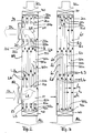
- Figure 1 illustrates a plan view of the flat side 51 of the flat cooling unit.
- two recesses 13, 23 are provided, which are aligned substantially along a center plane A, but have a significant distance in the direction of length I of the flat cooling unit. They are each arranged at a distance I 23 , I 13 of their respective centers of the upper and lower front end of the flat cooling unit in the front flat side 51.
- the recesses 23, 13 are circular and in cross-section along the plane A cylindrical spaces extend into the depth h of the cooling unit, see. FIG . 2 .
- the width of the cooling unit extends perpendicular to the length and is designated b in Figure 1.
- the heat sink is much longer than it is wide.
- the depth (thickness or thickness) in the direction h is again much smaller than the width. However, the depth can also be significantly increased if several of the sheet metal walls 50a, 50b, 50c to be described later are used to define the flow chambers k1, k2, k3,.
- the storage space 11 behind the inlet 13 and the collecting space 21 in front of the outlet 23 respectively cylindrical. These areas are also referred to as entry area and exit area.
- a first axial fan 10 is arranged, which pushes the warm air SL (suction air) to be cooled into the first stowage chamber 11 in an air flow.
- a second fan 20 may be disposed at the exit port 23 to provide cooled air receive the collection chamber 21 and return as compressed air DL in the circuit.
- the flat side 51 of Figure 1 is mounted as one or to a wall of a cabinet enclosure, such as a device cabinet, a server cabinet or a cabinet with corresponding openings, such as the door, a side wall or the rear wall.
- a cabinet enclosure such as a device cabinet, a server cabinet or a cabinet with corresponding openings, such as the door, a side wall or the rear wall.
- the openings 13, 23 access to the interior of the cabinet, which may be closed otherwise and will usually be closed. It then creates a circulation of the warm air volume in the cabinet through the heat exchanger, which in turn causes a cooling of the circulated cabinet air by cooling air KL countercurrent principle, which cooling air exits as exhaust air AL at the opposite end again.
- the airflow for cooling is schematically illustrated by arrows in FIG. It is supported by two input fans 30, 31 shown here, which are arranged adjacent and electrically connected in parallel. Also arranged adjacent and electrically also connected in parallel are two outlet fans 40, 41, all fan according to the principle of axial ventilation, ie with a rotation axis and an inner support, are arranged on the radial wings, which compress and promote the air. Air enters axially and axially, with the end of the inlet fans 30, 31 defining the beginning of the heat exchanger and the beginning of the outlet fans 40, 41 the end of the heat exchanger.
- the openings 13, 23 are arranged at a distance from the lower end and the upper end, they also have a distance b1, b2 and b3, b4 from the lateral longitudinal sides (narrow sides) of the heat exchanger.
- the inflow region 13 and the outflow region 23 are thus placed in the heat exchanger so that - seen in the flow direction of the cooling air KL - an exchanger surface is also found in front of the outlet region 23 and after the inlet region 13.
- Also next to the outlet area and adjacent to the inlet area exchanger surfaces are provided, so that a flushing of the here cylindrically shaped collection chamber or storage chamber 21, 11 is possible.
- the flow widths b1, b2 and b3, b4 should in each case taken together at least on the order of the diameter d13 and d23 of the opening 13, 23rd lie, but may preferably be made larger.
- the number of axial fans 30, 31, 40, 41 on the input end face and the output end face of the flat cooling unit depends on its dimensions. It can also be connected in parallel more axial fans, as well as less.
- This orientation of the flow chambers illustrate the two sections along the planes A and B, the section along the plane A illustrating the stagnation chamber and the collection chamber 11, 21, while the sectional view of Figure 3 along the plane B illustrates the entire flow path on which it can be seen that the webs 32 and the webs 42 in each case seal the same chamber on the front side (towards the outside).
- These two-dimensional flow chambers k1, k3, k5, k7 are those flow chambers (with odd indices) which receive the upwardly flowing, to be cooled hot air L3.
- the flow chambers k2, k4, k6, k8 which are in connection with the outside air in FIG. 3 are those flow chambers which receive the cooling outside air L4 and lead in countercurrent to the air flow L3 in the other chambers with the odd k indices. They are not closed at the end faces with webs, but in the areas of the inflow 13 and the outflow 23 for the (heated) air to be cooled.
- the webs 22a, 22b, 22c formed here (22 for short) and 12a, 12b, 12c (12 for short) seal the flow spaces of the outside air against the inside air tightly. These webs are schematically visible in the plan view of Figure 1 around the inlet 13 and around the outlet 23 around. They provide as well as the webs 32, 42 for a physical Separation of the elongated, flat flow chambers that carry the outside air and those other parallel flow chambers, which carry the indoor air.
- each flow chamber between the front, longitudinal sides 52, the front narrow sides 32, 42 and the webs 12 and 22 extends around inlet and outlet area.
- the areal extent of the chambers is thus substantially greater in their width and longitudinal direction than the height h of each of the chambers, the height being indicated by h1 for the chamber k1 and the height h2 for the chamber k2 in FIG.
- the other heights of the other chambers are corresponding.
- All chambers have the same web height practically the same height (thickness or thickness) with individual sheet metal layers 50a, 50b, 50c each of the chambers areally limited.
- the sheet metal layers may additionally be made uneven perpendicular to their extension, for example by corrugation or embossed knobs to increase the heat exchange surface between the chambers. But they are impermeable to the flow of air to physically separate the cooling air from the air to be cooled.
- the chamber heights were less than 10 mm, preferably less than 5 mm.
- the webs 12, 42 and 22, 32 are glued in the example with the sheets 50a, 50b, 50c, etc., in order to achieve an airtight seal.
- the stacked webs 52 may be glued in the frontal longitudinal region with the sheets in the edge region, in addition also be reinforced by a screw fastening.
- a respective arcuate cover plate 18, 28 is added as a flow barrier. It can extend completely into the depth of the storage space 11 and into the depth of the collecting space 21.
- the heat exchanger of Figure 4 in the plane B is formed as described with reference to Figures 1 to 3.
- a sectional view of the heat exchanger of Figure 4 would correspond exactly to that sectional view of Figure 3, with the same countercurrent principle and the same chamber height of the flat flow chambers.
- the vote of the electrical performance of the fan, or their sizes or their actually operated speed should preferably be such that the fan 10 is operated at a greater power than the fan 20.
- the stowage chamber 11 is replaced by a greater pressure than he can be reduced from the collection chamber 21 by the negative pressure.
- this technical design or this technical operation of the heat exchanger provide greater turbulence and increase the turbulence effect in the flat flow chambers.
- Different measures for changing the performance of the lower fan are alternatively possible. Different fan types (by size) can be used with regard to fans 10 or 20. It is possible to use the same fans, which are operated differently, and it is possible to use different fans, which are operated differently, but according to the same described specification.
- the fans 30, 31 and 40, 41 should be substantially the same, ie achieve the same air throughput.
- the cooling effects achieved with the arrangement described could be increased by 20% to 30% if the deflection surface or guide surface in the sense of locking pieces 18, 28 was added to the embodiment of FIG. 1, which is already outstanding in heat exchange performance.
- the residence time of the air to be cooled in the elongated flat chambers is achieved in addition to increasing the turbulence.
- the shortest path ie the short circuit for the guided in the U-shaped flow of movement air SL, L3, DL is blocked and despite maintaining the substantially U-shaped flow direction, the lateral sections b3, b4, b1, b2 next to the inflow opening 13 and next the outflow opening 23 participates in the heat exchange, which also applies to the front section I 23 and the rear section I 13 of the heat exchanger, based on the flow direction of the outer cooling air KL, AL.
- the external cooling air can exert its cooling effect ..
- a flushing of the The circulation can be affected when the arcuate locking pieces 18, 28 are adjusted, which adjustment can be oriented both in the circumferential direction, as well as in the axial direction by pushing in and out of the cylindrical storage chamber 11 and the cylindrical receiving chamber 21.
- the shape of the chambers 11, 21 is not limited to a cylindrical shape, but also in the immediate vicinity deviating geometries can be selected, such as ellipses and Peecke. But it is advantageous if the chamber extends to the very depth of the heat exchanger and occupy the entire height h of the flat cooling unit.
Landscapes
- Engineering & Computer Science (AREA)
- Aviation & Aerospace Engineering (AREA)
- Physics & Mathematics (AREA)
- Thermal Sciences (AREA)
- Microelectronics & Electronic Packaging (AREA)
- Cooling Or The Like Of Electrical Apparatus (AREA)
- Heat-Exchange Devices With Radiators And Conduit Assemblies (AREA)
- Medicines Containing Plant Substances (AREA)
- Vaporization, Distillation, Condensation, Sublimation, And Cold Traps (AREA)
Abstract
Description
Die Erfindung befasst sich mit einem flächigen Kühlaggregat zur Verwendung als Wärmetauscher bei der Kühlung von Luft aus beispielsweise einem Geräteschrank, einem Serverschrank oder einem Schaltschrank, in welchen Wärme erzeugende Einrichtungen eingebaut sind, deren Wärme aus der im wesentlichen geschlossenen Gehäuseanordnung abzuführen ist, um eine Innentemperatur dieser Gehäuse-Anordnungen nicht über einen vorgegebenen Maximalwert steigen zu lassen.The invention relates to a flat cooling unit for use as a heat exchanger in the cooling of air from, for example, a cabinet, a server cabinet or a cabinet in which are installed heat generating devices whose heat is dissipated from the substantially closed housing assembly to an internal temperature these housing arrangements do not rise above a predetermined maximum value.
Wärmetauscher im Sinne eines Gegenstromprinzips, bei dem Kühlluft in die eine Richtung strömt und in davon getrennten Strömungskammern die zu kühlende Luft in die andere Richtung strömt, sind als solche schon dem Stand der Technik zuzurechnen, vgl. beispielsweise DE-A 30 44 135 (Siemens). Dort ist ein Wärmetauscher mit Strömungskanälen beschrieben, die mit ihrem Querschnitt im wesentlichen senkrecht zur Flachseite des Wärmetauschers orientiert sind und längs verlaufen, vgl. dortige Figur 2 sowie hinsichtlich des Gegenstromprinzips die dortige Spalte 6, Zeilen 10 bis 20. Zur Beschickung der so orientierten Kühlkammern mit der zu kühlenden Luft werden Radiallüfter oder Tangentiallüfter eingesetzt, die an den Enden des Wärmetauschers in dreieckförmigen Staukammern eingebaut sind, um die Luft axial anzusaugen und radial in die Staukammern hineinzudrücken (bei der Einströmöffnung für die zu kühlende Luft). Entsprechendes gilt auch am entgegengesetzten Ende bei der Einströmöffnung für die Kühlluft. Sinn und Zweck der beschriebenen Lösung des Standes der Technik ist es, die strömende Luft nahezu gleichmäßig auf alle Strömungskanäle zu verteilen, bei möglichst hoher Ausnutzung des Gehäusevolumens für den Wärmetauscher.Heat exchangers in the sense of a countercurrent principle, in which cooling air flows in one direction and flows in separate flow chambers, the air to be cooled in the other direction, are already attributable to the prior art, see. for example DE-A 30 44 135 (Siemens). There, a heat exchanger with flow channels is described, which are oriented with its cross section substantially perpendicular to the flat side of the heat exchanger and run longitudinally, see. Figure 2 there and with respect to the countercurrent principle the local column 6,
Eine nicht im Gegenstromprinzip arbeitende Tauscheranordnung ist beispielsweise beschrieben in der DE-A 198 04 904 (Rittal), wo spezifische Stellen im Innenraum, die einer erhöhten Wärmeabgabe unterliegen, mit Schläuchen gesondert gekühlt werden können, wobei diese Kühlschläuche leicht an unterschiedliche Gegebenheiten des Innenraums angepasst werden können (vgl. dort die einzige Figur sowie Spalte 1, Zeilen 54 bis 58.) Ein doppelwandiges Wandelement auf der Schrank(rück)seite sorgt für den Wärmetausch, wobei allerdings kein Gegenstromprinzip eingesetzt wird.A non-countercurrent exchanger arrangement is described, for example, in DE-A 198 04 904 (Rittal), where specific places in the interior, which are subject to increased heat output, can be cooled separately with hoses, these cooling hoses easily adapted to different conditions of the interior (see there the only figure and column 1, lines 54 to 58.) A double-walled wall element on the cabinet (rear) side ensures the heat exchange, although no countercurrent principle is used.
Die Erfindung hat es sich zur Aufgabe gestellt, die Leistungsfähigkeit von Gegenströmüngs-Wärmetauschern weiter zu erhöhen, wobei die Verlustwärme so aus dem Gehäuse oder eventuell einem Gerät, das Schrankgröße besitzt, abgeführt werden soll, dass ein geringerer Anstieg der Innentemperatur pro abgegebenen Watt Verlustleistung in dem Gehäuse oder Schrank entsteht (°K pro Watt oder W/°K).The invention has set itself the task of further increasing the performance of Gegenströmüngs heat exchangers, the heat loss is so from the housing or possibly a device that has cabinet size, to be dissipated, that a smaller increase in the internal temperature per watt dissipated power loss in housing or cabinet (° K per watt or W / ° K).
Gelöst wird die Aufgabe mit einem flächigen Kühlaggregat im Gegenstromprinzip, nach zumindest einem der unabhängigen Ansprüche 1 oder 14.The object is achieved with a flat cooling unit in countercurrent principle, according to at least one of the independent claims 1 or 14.
Anspruch 14 kann die Arbeitsweise von Anspruch 1 sein, Vgl. Anspruch 19.Claim 14 may be the operation of claim 1, Cf. claim 19.
Die Luft im Innenkreis und im Außenkreis wird genau im Gegenstrom geführt. Damit wird eine maximale Wirksamkeit erreicht. Statt Radiallüftern werden Axiallüfter eingesetzt, deren Leistungsfähigkeit wesentlich höher ist (Anspruch 3) und außerdem weniger Umlenkungen für die zu bewegende (strömende) Luft bereitstellen. Die axial angesaugte Luft wird auch axial abgeführt und im Einlassbereich in den Gegenstrom-Wärmetauscher hineingedrückt, während am Auslassbereich ebenfalls ein solcher Axiallüfter - beabstandet von dem Eingangsbereich - angeordnet sein kann, der die dann gekühlte Luft aus dem Wärmetauscher herauszieht und zurück in den Schaltschrank, Serverschrank oder Geräteschrank oder ein einzelnes großes Gerät hineinbringt (Anspruch 1, 14). Günstig für die Erhöhung des Wärmetauschs ist dabei ein Unterschied in der Leistungsfähigkeit, der eingestellten Drehzahl oder der Größe der beiden Lüfter, die den zu kühlenden Luftstrom verursachen. Der Lüfter an dem Einlassbereich soll mit einer größeren Leistung betrieben werden, betreibbar sein oder mit einer höheren Drehzahl betrieben werden, als derjenige am Auslassbereich. Hinsichtlich der Kühlluft, die von ebenfalls zwei Axiallüftern im Gegenstromprinzip bereitgestellt wird, ist es günstig, wenn diese beiden Lüfter am Einlassbereich der Kühlluft und am Auslassbereich der Kühlluft (der Abluft) im wesentlichen die gleiche Leistungsfähigkeit, Drehzahl oder Leistungseinstellung besitzen. Trotz Bereitstellung einer maximal möglichen kühlenden Luft wird durch das erhöhte Einbringen der zu kühlenden Luft eine längere Verweildauer der zu kühlenden Luft erreicht und - nach derzeitigem Wissensstand - auch die Verwirbelung oder die Turbulenzen innerhalb der Strömungskammern erhöht, was zu einem verbesserten Wärmetausch mit der entgegenströmenden Kühlluft führt.The air in the inner circle and in the outer circle is guided exactly in countercurrent. This achieves maximum effectiveness. Instead of centrifugal fans axial fans are used, whose performance is much higher (claim 3) and also provide fewer deflections for the moving (flowing) air. The axially drawn in air is also discharged axially and pressed in the inlet region in the counterflow heat exchanger, while at the outlet region also such an axial fan - spaced from the input area - can be arranged, which then extracts the cooled air from the heat exchanger and back into the control cabinet, Server cabinet or equipment cabinet or a single large device brings in (claim 1, 14). Favorable for increasing the heat exchange is thereby a difference in the performance, the set speed or the size of the two fans that cause the air flow to be cooled. The fan at the inlet area should be operated at a higher power, be operable or operated at a higher speed than that at the outlet area. With respect to the cooling air provided by also two axial countercurrent fans, it is preferable that these two fans have substantially the same capacity, speed or power setting at the inlet portion of the cooling air and the outlet portion of the cooling air (the exhaust air). Despite providing a maximum possible cooling air is achieved by the increased introduction of the air to be cooled a longer residence time of the air to be cooled and - according to current knowledge - also increases the turbulence or turbulence within the flow chambers, resulting in improved heat exchange with the opposite cooling air leads.
Der Strömungsweg der Kühlluft ist dabei praktisch geradlinig (Anspruch 1). Zwischen dem Ausgang des ersten Lüfters und des zweiten Lüfters verläuft der Weg der Kühlluft praktisch geradlinig durch die Kammern, lediglich unterbrochen von dem Einströmbereich und dem Ausströmbereich der zu kühlenden Luft, die in keinem physischen Kontakt mit der Kühlluft steht, sondern durch getrennte Kammern imThe flow path of the cooling air is practically rectilinear (claim 1). Between the output of the first fan and the second fan, the path of the cooling air is practically straight through the chambers, only interrupted by the inflow and outflow of the air to be cooled, which is in no physical contact with the cooling air, but by separate chambers in the
Gegenstromprinzip geleitet wird (Anspruch 14).Countercurrent principle is passed (claim 14).
Statt einem Lüfter können auch mehrere Lüfter jeweils parallel geschaltet sein, je nach Ausbildung, Form und Größe des flächigen Kühlaggregats (Anspruch 3).Instead of a fan and several fans can be connected in parallel, depending on the design, shape and size of the flat cooling unit (claim 3).
Die U-förmige Ausbildung des Strömungsweges für die zu kühlende Luft hat sich als insoweit günstig erwiesen, als diese Luft möglichst wenig Umlenkungen während ihres Strömungsweges erfährt, wobei die Axiallüfter einen Beitrag leisten. Ausgehend von einem Einlassbereich, insbesondere in zylindrischer Gestaltung, wird Luft in eine erste Staukammer gedrückt, die unter Überdruck durch Wirkung des ersten Lüfters steht. Von dieser Staukammer wird die Luft auf eine Vielzahl paralleler Flächenkammern verteilt, die sich flächig parallel zur Flachseite des Wärmetauschers erstrecken. Am Auslassbereich, der in einem deutlichen Abstand vom Einlassbereich im wesentlichen senkrecht zur Flachseite des Wärmetauschers orientiert angeordnet ist, sammelt sich die gekühlte Luft aus den einzelnen, parallelen und beabstandeten Flächenkammern wieder in einem im wesentlichen zylindrischen Sammelraum, aus dem sie als gekühlte Luft in den Bereich zurückgegeben wird, in welchem die Wärme entsteht. An dieser Stelle kann ein weiterer (in den Ansprüchen als vierter Lüfter bezeichneter) Axiallüfter angeordnet werden, der die Luft aus dem Sammelraum abzieht, bevorzugt aber mit einer geringeren Leistung, als demjenigen ersten Lüfter, der die Luft in den ersten Stauraum einbringt (Ansprüche 11,12,18).The U-shaped design of the flow path for the air to be cooled has proven to be favorable in so far as this air experiences as few deflections during its flow path, the axial fans make a contribution. Starting from an inlet region, in particular in a cylindrical design, air is forced into a first stagnation chamber, which is under positive pressure by the action of the first fan. From this storage chamber, the air is distributed to a plurality of parallel surface chambers, which extend flat parallel to the flat side of the heat exchanger. At the outlet region, which is oriented at a considerable distance from the inlet region substantially perpendicular to the flat side of the heat exchanger, the cooled air from the individual, parallel and spaced surface chambers collects again in a substantially cylindrical collecting space, from which they are cooled in the air Area is returned, in which the heat is generated. At this point, another (referred to in the claims as the fourth fan) axial fan can be arranged, which withdraws the air from the plenum, but preferably with a lower power than that first fan, which introduces the air in the first storage space (claims 11 , 12.18).
Mit einer solchen Gestaltung ist es möglich, die verfügbare Baulänge und somit auch die Fläche für das zum Wärmetausch verwendete Blechpaket vollständig auszunutzen und im Bleckpaket selbst keine Räume freizustellen oder aussparen zu müssen, die einen Lüfter aufnehmen. Dazuhin ergibt sich durch die Lage und Bauhöhe der flachen Strömungskanäle eine turbulente, verwirbelnde Strömung, die bevorzugt mit an der Oberfläche nicht ebenen Platten (Anspruch 6) eine erhöhte Tauscherleistung zur Verfügung stellt.With such a design, it is possible to fully exploit the available length and thus also the area for the laminated core used for heat exchange and in the Bleckpaket itself do not have to indemnify or exclude spaces that receive a fan. Given by the position and height of the flat flow channels, a turbulent, swirling flow, preferably with an on the surface not flat plates (claim 6) provides increased heat exchanger performance.
Die als flächige Kammern bezeichneten Strömungskammern für die zu kühlende Luft und auch für die Kühlluft haben bezogen auf ihre Breite und Länge eine nur geringe Höhe. Breite und Höhe ist hier so zu verstehen, dass diese beiden Maße eine Ebene parallel zur Flachseite des Wärmetauschers beschreiben, während die Höhe in Richtung der Dicke, also senkrecht zur flächigen Erstreckung des flachen Kühlaggregats definiert ist (Anspr. 16, 17).The flow chambers designated as two-dimensional chambers for the air to be cooled and also for the cooling air have only a small height relative to their width and length. Width and height is to be understood here that these two dimensions describe a plane parallel to the flat side of the heat exchanger, while the height in the direction of the thickness, that is defined perpendicular to the flat extent of the flat cooling unit (claims 16, 17).
Die Tauscherleistung wird auch dadurch erhöht, dass der Gegenstromaustausch nicht erst nach dem Einlass und bis hin zum Auslass der zu kühlenden Luft erfolgt, sondern auch darüber hinaus, also dem Auslass nachgelagert und dem Einlass vorgelagert (Anspruch 15).The exchanger performance is also increased by the fact that the countercurrent exchange does not take place only after the inlet and up to the outlet of the air to be cooled, but also beyond, ie downstream of the outlet and upstream of the inlet (claim 15).
Die insoweit im Gegenstromprinzip abwechselnd angeordneten flächigen Strömungskammern für Kühlluft und zu kühlende Luft erstrecken sich auch zwischen dem Ausströmende des Wärmetauschers und dem Einlassbereich sowie zwischen dem Einströmbereich der Kühlluft und dem Auslassbereich der zu kühlenden Luft, die hier bereits als die "gekühlte Luft" bezeichnet wird.The so far in the countercurrent principle alternately arranged planar flow chambers for cooling air and air to be cooled also extend between the outflow end of the heat exchanger and the inlet region and between the inflow of the cooling air and the outlet of the air to be cooled, which is already referred to here as the "cooled air" ,
Zur Terminologie sei angemerkt, dass die "zu kühlende Luft" als diejenige Luft beschrieben wird, die als Brauchluft innerhalb des Schranksystems umgewälzt und dabei gekühlt wird. Sie hat an ihrem Austritt die niedrigst mögliche Temperatur und wird hier als gekühlte Luft bezeichnet, oft aber auch - zur Darstellung des Kreislaufes - im Zuge ihres Gesamtverlaufes als zu kühlende Luft. Die Nutzluft, mit welcher der Wärmetauscher gekühlt wird, wird als Kühlluft bezeichnet, die im Auslassbereich, also dort, wo sie ihre maximale Temperatur besitzt, als Abluft benannt wird. Dennoch bleibt die Kühlluft auch während ihrer gesamten Strömungsstrecke im Tauscher als solche benannt, um eine sinngemäß einheitliche Terminologie für die zu beschreibende Erfindung zu erhalten.With regard to terminology, it should be noted that the "air to be cooled" is described as the air which is circulated as domestic air within the cabinet system and thereby cooled. It has at its outlet the lowest possible temperature and is referred to here as cooled air, but often also - to represent the cycle - in the course of their overall course as air to be cooled. The useful air, with which the heat exchanger is cooled, is referred to as cooling air, which is called in the outlet, where it has its maximum temperature, as exhaust air. Nevertheless, the cooling air remains named as such during its entire flow path in the exchanger in order to obtain a mutually consistent terminology for the invention to be described.
Auch anzumerken ist, dass bei der Umschreibung eines flächigen Kühlaggregats die Funktion und Wirkungsweise dieses Aggregats oft durch Verwendung der Luftströmungen und der strömenden Luft beschrieben wird, was aber nicht insoweit einschränkend verstanden werden soll, als dass damit nur der aktuelle Betrieb gemeint ist. Der aktuelle Betrieb ist vielmehr von einem Verfahrensanspruch (Anspruch 14) umfasst, mit welchem erläutert wird, dass der Einlassbereich und der Auslassbereich der zu kühlenden Luft nicht die Enden des jeweiligen Wärmetauschers sind, sondern zwischen diesen Bereichen und dem jeweiligen stirnseitigen Ende (Anfang) auch noch Kühlbereiche im Gegenstromprinzip platziert sind. Das wird so umschrieben, dass an dem Einlassbereich vorbei kühlende Kühlluft noch zu strömen vermag, alternativ oder kumulativ auch hinter dem Auslassbereich der gekühlten Luft noch kühlende Frischluft im Gegenstrom-Wärmetauschprinzip eingesetzt werden kann.It should also be noted that in the description of a flat cooling unit, the function and mode of operation of this unit is often described by using the air currents and the flowing air, but this should not be understood as limiting, as this means only the current operation. Rather, the actual operation is covered by a method claim (claim 14), with which it is explained that the inlet area and the outlet area of the air to be cooled are not the ends of the respective heat exchanger but also between these areas and the respective front end (beginning) still cooling areas are placed in countercurrent principle. This is so circumscribed that cooling air flowing past the inlet area is still able to flow, alternatively or cumulatively, still cooling fresh air in countercurrent heat exchange principle can be used behind the outlet area of the cooled air.
Wenn die Kühlluft am Einlassbereich der zu kühlenden Luft noch vorbeiströmt und die kühlende Luft schon vor dem Auslassbereich strömt (Anspruch 15) ist dies in den Bereichen von Einlass und Auslass (der zu kühlenden Luft) jeweils so vorgesehen, dass es auf einer Breite erfolgt, die nicht geringer ist, als diejenige Breite, insbesondere der Durchmesser, des Einströmbereichs oder des Ausströmbereichs selber.When the cooling air still flows past the inlet portion of the air to be cooled and the cooling air flows before the outlet portion (claim 15), it is provided in the regions of the inlet and outlet (the air to be cooled) so as to be on a width, which is not less than that width, in particular the diameter, of the inflow region or of the outflow region itself.
Aus der Höhe der strömenden Luftschichten (Anspruch 17) ist auch auf den Abstand der die Kammern trennenden metallischen Bleche zu schließen (Anspruch 17). Letztere Kammern sind mit Trennelementen in Form von Stegen so abgedichtet, dass jeweils ein getrenntes Kammersystem für die kühlende Luft und ein getrenntes Kammersystem für die zu kühlende Luft entsteht, die sich abwechseln (Ansprüche 6, Ziffer (a), 2, 4, 5 sowie 13).From the height of the flowing air layers (claim 17) is also on the distance of the chambers separating metallic plates to close (claim 17). The latter chambers are sealed with dividing elements in the form of webs so that in each case a separate chamber system for the cooling air and a separate chamber system for the air to be cooled is formed, which alternate (claims 6, paragraph (a), 2, 4, 5 and 13).
Eine weitere Erhöhung der Kühlleistung oder der Wärmeabgabeleistung im Wärmetauscher erreicht man mit Sperrstücken (Anspruch 7), welche einen direkten (kurzen) Strömungsweg für die zu kühlende Luft sperren und diese Luft zur Begünstigung einer Verwirbelung oder einer turbulenten Strömung aus dem kürzesten Strömungsweg ablenken und in einen längeren Strömungsweg zwingen. Diese Sperrstücke können als Bogenstücke ausgebildet sein, insbesondere verstellbar (Anspruch 8,9). Sie sind im Einlassbereich und im Auslassbereich angeordnet, bevorzugt gegenüberliegend.A further increase in the cooling capacity or the heat output in the heat exchanger can be achieved with locking pieces (claim 7), which block a direct (short) flow path for the air to be cooled and distract this air to favor a turbulence or a turbulent flow from the shortest flow path and in force a longer flow path. These locking pieces may be formed as elbows, in particular adjustable (claim 8,9). They are arranged in the inlet area and in the outlet area, preferably opposite each other.
Die Erfindung erreicht es, mit solwenig rechtwinkligen Umlenkungen wie möglich die Gegenstrom-Strömungsleistung zu sichern und dabei die verfügbaren Kammern so vollständig und so gleichmäßig wie möglich auszunutzen. In technischen Versuchen konnte erprobt werden, dass ein Wärmetauscher eine mehr als doppelt so große Kühlleistung erzielte, als derzeit verfügbare Luft-Wärmetauscher im Gegenstromprinzip. Erreicht wurden Werte von oberhalb 400 W/°K, die bei einer Größenordnung des Wärmetauschers mit Außenabmessungen von 100cm Länge, 40cm Breite und 18cm Höhe (Dicke/Stärke) erreicht wurde.The invention achieves, as far as possible, the countercurrent flow performance with as few right-angled deflections, while making full use of the available chambers as evenly as possible. In technical experiments could be tested that a heat exchanger achieved more than twice as large cooling capacity, as currently available air heat exchangers in countercurrent principle. Values of above 400 W / ° K were achieved, which was achieved with a size of the heat exchanger with external dimensions of 100 cm length, 40 cm width and 18 cm height (thickness / thickness).
Die Erfindung wird im folgenden an Ausführungsbeispielen erläutert und ergänzt.
- Figur 1
- ist eine Ansicht auf die
Flachseite 51 eines Wärmetauschers mit einerEinströmöffnung 13 und einerAusströmöffnung 23 für die zu kühlende Luft bzw. die gekühlte Luft. Zwei Schnittlinien A und B sind angedeutet. - Figur 2
- ist ein Querschnitt entlang der Ebene A von Figur 1.
- Figur 3
- ist ein Querschnitt entlang der Ebene B von Figur 1.
- Figur 4
- veranschaulicht eine vorteilhafte Ergänzung der Anordnung nach Figur 1, wobei die Querschnitte der Figuren 2 und 3 entsprechend auch für diese Anordnung gelten, mit den
entsprechenden Abschnitten
- FIG. 1
- is a view of the
flat side 51 of a heat exchanger with aninflow opening 13 and anoutflow opening 23 for the air to be cooled or the cooled air. Two section lines A and B are indicated. - FIG. 2
- is a cross-section along the plane A of Figure 1.
- FIG. 3
- is a cross-section along the plane B of Figure 1.
- FIG. 4
- 1 illustrates an advantageous supplement to the arrangement according to FIG. 1, the cross sections of FIGS. 2 and 3 also correspondingly being valid for this arrangement, with the corresponding
sections
Figur 1 veranschaulicht eine Aufsicht auf die Flachseite 51 des flächigen Kühlaggregats. In der Flachseite 51 sind zwei Aussparungen 13, 23 vorgesehen, die im wesentlichen entlang einer Mittelebene A ausgerichtet sind, aber einen deutlichen Abstand in Längenrichtung I des flächigen Kühlaggregats besitzen. Sie sind jeweils in einem Abstand I23, I13 ihrer jeweiligen Mitten von dem oberen und unteren Stirnende des flächigen Kühlaggregats in der vorderen Flachseite 51 angeordnet. Die Aussparungen 23, 13 sind kreisförmig und im Querschnitt entlang der Ebene A erstrecken sich zylindrische Räume in die Tiefe h des Kühlaggregats, vgl. Figur 2. Die Breite des Kühlaggregats erstreckt sich senkrecht zur Länge und ist mit b in Figur 1 bezeichnet. Der Kühlkörper ist wesentlich länger, als er breit ist. Die Tiefe (Dicke oder Stärke) in Richtung h ist wiederum wesentlich geringer, als die Breite. Die Tiefe kann aber auch deutlich erhöht werden, wenn mehrere der später zu beschreibenden Blechwände 50a, 50b, 50c zur Definition der Strömungskammern k1, k2, k3,... verwendet werden. Figure 1 illustrates a plan view of the
Bei Zugrundelegung einer kreisförmigen Öffnung 13 für den Eintritt der zu kühlenden Warmluft und einer kreisförmigen Öffnung 23 für den Austritt der gekühlten Warmluft bzw. der in den Schaltschrank zurückkehrenden Kaltluft, sind der Stauraum 11 hinter dem Eintritt 13 und der Sammelraum 21 vor dem Austritt 23 jeweils zylindrisch. Diese Bereiche werden auch als Eintrittsbereich und Austrittsbereich bezeichnet. Vor dem Eintrittsbereich 13 ist ein erster Axiallüfter 10 angeordnet, der die zu kühlende warme Luft SL (Saugluft) in einem Luftstrom in die erste Staukammer 11 hineindrückt. Ein zweiter Lüfter 20 kann an der Austrittsöffnung 23 angeordnet sein, um gekühlte Luft aus der Sammelkammer 21 aufzunehmen und als Druckluft DL in den Kreislauf zurückzugeben.On the basis of a
Die Flachseite 51 von Figur 1 wird als eine oder an eine Wand eines Schrankgehäuses, beispielsweise eines Geräteschrankes, eines Serverschrankes oder eines Schaltschrankes mit entsprechenden Öffnungen montiert, so beispielsweise die Tür, eine Seitenwand oder die Rückwand. Dadurch haben die Öffnungen 13, 23 Zutritt zu dem Inneren des Schrankes, der im übrigen geschlossen sein kann und meist auch geschlossen sein wird. Es entsteht dann eine Umwälzung des warmen Luftvolumens im Schrank durch den Wärmetauscher hindurch, der seinerseits durch Kühlluft KL im Gegenstromprinzip eine Kühlung der zirkulierten Schrankluft verursacht, welche Kühlluft als Abluft AL am entgegengesetzten Stirnende wieder austritt.The
Dieser Durchfluß der kühlenden Luft KL, L4, AL erfolgt entlang von Strömungskammern, die im Schnitt später erläutert werden.This flow of cooling air KL, L4, AL takes place along flow chambers, which will be explained in section later.
Der Luftstrom zum Kühlen ist schematisch durch Pfeile in Figur 1 veranschaulicht. Er wird unterstützt durch hier eingezeichnete zwei Eingangslüfter 30, 31, die benachbart angeordnet und elektrisch parallel geschaltet sind. Ebenfalls benachbart angeordnet und elektrisch ebenfalls parallel geschaltet sind zwei Ausgangslüfter 40, 41, alles Lüfter nach dem Prinzip der Axiallüftung, also mit einer Drehachse und einem Innenträger, an dem radiale Flügel angeordnet sind, welche die Luft komprimieren und fördern. Luft tritt hierbei axial ein und axial aus, wobei das Ende der Eingangslüfter 30, 31 den Beginn des Wärmetauschers definiert und der Beginn der Austrittslüfter 40, 41 das Ende des Wärmetauschers.The airflow for cooling is schematically illustrated by arrows in FIG. It is supported by two
Nachdem die Öffnungen 13, 23 im Abstand vom unteren Ende und vom oberen Ende angeordnet sind, besitzen sie auch einen Abstand b1, b2 bzw. b3, b4 von dem lateralen Längsseiten (Schmalseiten) des Wärmetauschers. Der Einströmbereich 13 und der Ausströmbereich 23 sind damit so in dem Wärmetauscher plaziert, daß - in Strömungsrichtung der kühlenden Luft KL gesehen - eine Tauscherfläche auch vor dem Austrittsbereich 23 und nach dem Eintrittsbereich 13 angetroffen wird. Auch neben dem Austrittsbereich und neben dem Eintrittsbereich sind Tauscherflächen vorgesehen, so daß ein Umspülen der hier zylindrisch ausgeformten Sammelkammer bzw. Staukammer 21, 11 möglich ist.After the
Die Strömungsbreiten b1, b2 sowie b3, b4 sollten jeweils zusammengenommen zumindest in der Größenordnung des Durchmessers d13 und d23 der Öffnung 13, 23 liegen, können bevorzugt aber auch größer ausgestaltet sein. Die Anzahl der Axiallüfter 30, 31, 40, 41 auf der Eingangsstirnseite und der Ausgangsstirnseite des flächigen Kühlaggregats hängt von dessen Abmessungen ab. Es können ebenso mehrere Axiallüfter parallel geschaltet sein, wie auch weniger.The flow widths b1, b2 and b3, b4 should in each case taken together at least on the order of the diameter d13 and d23 of the
An den Längs-Stirnseiten ist der Wärmetauscher geschlossen, was durch einen Stapel von Stegen 52 erreicht wird, welche die einzelnen Kammern zwischen der hinteren Rückwand 50 und der in Figur 1 sichtbaren Frontwand 51 vollständig abdichten. Im oberen Stirnbereich sind ebenfalls Abdichtungsstege 32a, 32b, 32c,... vorgesehen, die aber nur jede zweite Kammer zur Außenseite hin abdichten, wie auch im unteren Stirnbereich nahe den Lüftern 40,41 nur jede zweite Kammer mit Stegen 42a, 42b, 42c, kurz 42 zur Außenseite hin abgedichtet sind. Diejenigen Kammern, die stirnseitig mit den Stegen 32 bzw. 42 abgedichtet sind, sind dieselben Kammern, bzw. die Stege 32, 42 befinden sich auf derselben Ebenenhöhe, bezogen auf die Flachseite 51.At the longitudinal end faces of the heat exchanger is closed, which is achieved by a stack of
Diese Orientierung der Strömungskammern veranschaulichen die beiden Schnitte entlang den Ebenen A und B, wobei der Schnitt entlang der Ebene A die Staukammer und die Sammelkammer 11, 21 mit veranschaulicht, während die Schnittdarstellung der Figur 3 entlang der Ebene B den gesamten Strömungsweg veranschaulicht, an dem ersichtlich ist, daß die Stege 32 und die Stege 42 jeweils dieselbe Kammer stirnseitig (zum Außenraum hin) abdichten. Diese flächigen Strömungskammern k1, k3, k5, k7 sind diejenigen Strömungskammern (mit ungeraden Indizes), welche die aufwärts strömende, zu kühlende Warmluft L3 aufnehmen. Sie stammt aus der Staukammer 11 als Folge des Lüfterdrucks aus der Saugluft SL zum Luftstrom L1 und enden in der Sammelkammer 21, umgelenkt entlang des Strömungsweges L5 und angesaugt von dem Axiallüfter 20 zur Bildung von Druckluft DL am Ausgang des zweiten Axiallüfters 20.This orientation of the flow chambers illustrate the two sections along the planes A and B, the section along the plane A illustrating the stagnation chamber and the
Die in Figur 3 mit der Außenluft in Verbindung stehenden Strömungskammern k2, k4, k6, k8 sind diejenigen Strömungskammern, welche die kühlende Außenluft L4 aufnehmen und im Gegenstromprinzip zu dem Luftstrom L3 in den anderen Kammern mit den ungeraden k-Indizes führen. Sie sind nicht an den Stirnseiten mit Stegen verschlossen, sondern in den Bereichen der Einströmung 13 und der Ausströmung 23 für die zu kühlende (erwärmte) Luft. Die hier gebildeten Stege 22a, 22b, 22c, (kurz 22) und 12a, 12b, 12c (kurz 12) schließen die Strömungsräume der Außenluft gegenüber der Innenluft dicht ab. Diese Stege sind in der Aufsicht von Figur 1 um den Einlaß 13 herum und um den Auslaß 23 herum schematisch ersichtlich. Sie sorgen ebenso wie die Stege 32, 42 für eine physische Trennung der langgestreckten, flächigen Strömungskammern, die die Außenluft führen und denjenigen anderen parallelen Strömungskammern, welche die Innenluft führen.The flow chambers k2, k4, k6, k8 which are in connection with the outside air in FIG. 3 are those flow chambers which receive the cooling outside air L4 and lead in countercurrent to the air flow L3 in the other chambers with the odd k indices. They are not closed at the end faces with webs, but in the areas of the
Das Prinzip des Gegenstroms ist anhand der Figur 2 und 3 ersichtlich. Die Stapelung der einzelnen flächigen Strömungskammern ebenfalls und die flächige Erstreckung dieser flächigen Strömungskammern veranschaulicht die Figur 1, wobei sich jede Strömungskammer zwischen den stirnseitigen, Längsseiten 52, den stirnseitigen Schmalseiten 32, 42 und den Stegen 12 und 22 um Einlaßbereich und Auslaßbereich herum erstreckt. Die flächige Erstreckung der Kammern ist damit in ihrer Breiten- und Längsrichtung wesentlich größer, als die Höhe h jeder der Kammern, wobei die Höhe mit h1 für die Kammer k1 und die Höhe h2 für die Kammer k2 in Figur 3 angegeben ist. Die anderen Höhen der anderen Kammern sind entsprechend.The principle of the countercurrent can be seen with reference to FIGS. 2 and 3. The stacking of the individual flat flow chambers likewise and the planar extent of these two-dimensional flow chambers illustrated in Figure 1, wherein each flow chamber between the front,
Alle Kammern haben bei gleicher Steghöhe praktisch die gleichen Höhen (Dicken oder Stärken) wobei einzelne Blechlagen 50a, 50b, 50c jede der Kammern flächig begrenzt. Die Blechlagen können zusätzlich senkrecht zu ihrer Erstreckung uneben ausgestaltet sein, beispielsweise durch Wellung oder eingeprägte Noppen, um die Wärmetauscherfläche zwischen den Kammern zu vergrößern. Sie sind für die Luftströmung aber undurchlässig, um die kühlende Luft von der zu kühlenden Luft physisch zu trennen.All chambers have the same web height practically the same height (thickness or thickness) with individual
In einer beispielhaften Realisierung betrugen die Kammerhöhen weniger als 10 mm, bevorzugt weniger als 5 mm. Die Stege 12, 42 sowie 22, 32 sind im Beispiel mit den Blechen 50a, 50b, 50c, etc. verklebt, um einen luftdichten Abschluß zu erreichen. Ebenso können die gestapelten Stege 52 im stirnseitigen Längsbereich mit den Blechen im Randbereich verklebt sein, zusätzlich durch eine Schraubbefestigung auch noch verstärkt werden.In an exemplary implementation, the chamber heights were less than 10 mm, preferably less than 5 mm. The
Bei einer Ausbildung des Wärmetauschers so, wie in Figur 4 abgebildet, ergänzt sich am unteren Ende der Auslaßöffnung 23 und am oberen Ende der Einlaßöffnung 13 ein jeweiliges bogenförmig gestaltetes Abdeckblech 18, 28 als Strömungssperre. Sie kann sich ganz in die Tiefe des Stauraums 11 und in die Tiefe des Sammelraums 21 erstrecken. Im übrigen ist der Wärmetauscher von Figur 4 in der Ebene B so ausgebildet, wie anhand der Figuren 1 bis 3 beschrieben. Eine Schnittdarstellung des Wärmetauscher von Figur 4 würde genau derjenigen Schnittdarstellung von Figur 3 entsprechen, bei gleichem Gegenstromprinzip und gleicher Kammerhöhe der flächigen Strömungskammern. In der Figur 2 würde im Bereich des Austritts der zu kühlenden Luft L3 aus den Strömungskammern nahe den unteren Abschnitten der Stege 22a, 22b und unterhalb der oberen Stegabschnitte Stege 12a, 12b beim Eintritt des Luftstroms L1 in die Strömungskammer eine Abdeckung erfolgen, die aber nicht die gesamte Breite der flächigen Strömungskammern erreicht. Die Strömung L1 würde dann zunächst abgelenkt in die Seitenbereiche der Abschnitte b1, b2 am Einlaß und dann entlang des flächigen Mittelabschnitts des Strömungstauschers entlanggeführt werden. Eine dadurch entstehende zusätzliche Verwirbelung sorgt für eine Verstärkung des turbulenten Strömungseffektes und damit für eine stärkere Wärmetauschwirkung und höhere Wärmeübertragungs-Leistung an die entgegenströmende Kühlluft L4.In an embodiment of the heat exchanger as shown in FIG. 4 , at the lower end of the
Die Abstimmung der elektrischen Leistungen der Lüfter, oder aber ihrer Größen oder aber ihrer tatsächlich betriebenen Drehzahl sollte bevorzugt so erfolgen, daß der Lüfter 10 mit einer größeren Leistung betrieben wird, als der Lüfter 20. Die Staukammer 11 erhält so einen stärkeren Überdruck, als er von der Sammelkammer 21 aus durch deren Unterdruck reduziert werden kann. Auch diese technische Gestaltung oder dieser technische Betrieb des Wärmetauschers sorgen für eine stärkere Verwirbelung und eine Erhöhung des Turbulenzeffektes in den flachen Strömungskammern. Die verschiedenen Maßnahmen zur Veränderung der Leistung des unteren Lüfters sind alternativ möglich. Es können unterschiedliche Lüftertypen (nach Baugröße) hinsichtlich der Lüfter 10. oder 20 verwendet werden. Es können dieselben Lüfter verwendet werden, die unterschiedlich betrieben werden und es können unterschiedliche Lüfter verwendet werden, die unterschiedlich betrieben werden, aber nach der gleichen beschriebenen Maßgabe.The vote of the electrical performance of the fan, or their sizes or their actually operated speed should preferably be such that the
Die Lüfter 30, 31 und 40, 41 sollten dagegen im wesentlichen gleich stark sein, also gleichen Luftdurchsatz zu erreichen.On the other hand, the
Die mit der beschriebenen Anordnung erreichten Kühlungswirkungen konnten um 20 % bis 30 % erhöht werden, wenn die Ablenkfläche oder Leitfläche im Sinne von Sperrstücken 18, 28 zu der ohnehin schon in der Wärmetauschleistung hervorragenden Ausführungsform von Figur 1 hinzugenommen wurde. Die Verweildauer der zu kühlenden Luft in den langgestreckten Flachkammern wird dabei zusätzlich zu der Erhöhung der Verwirbelung erreicht. Der kürzeste Weg, also der Kurzschluß für die im U-förmigen Bewegungsstrom geleitete Luft SL, L3, DL wird gesperrt und trotz Beibehaltung der im wesentlichen U-förmigen Strömungsrichtung werden die lateralen Abschnitte b3, b4, b1, b2 neben der Einströmungsöffnung 13 und neben der Ausströmungsöffnung 23 an dem Wärmetausch beteiligt, was auch für den vorderen Abschnitt I23 und den hinteren Abschnitt I13 des Wärmetauschers gilt, bezogen auf die Strömungsrichtung der äußeren Kühlluft KL, AL. Um die Einlaßöffnung herum (außerhalb der abdichtenden Stege 12, und/oder um die Auslaßöffnung 23 herum (um die hier abdichtenden Stege 22) kann die äußere Kühlluft ihre Kühlungswirkung entfalten. Während des im wesentlichen linearen Durchtritts durch die zugehörigen Flachkanäle k2, k4, k8 kann ein Umspülen des Einströmbereiches und des Ausströmbereiches erreicht werden. Die Umspülung kann beeinflußt werden, wenn die bogenförmigen Sperrstücke 18, 28 verstellt werden, welche Verstellung sowohl in umfänglicher Richtung orientiert sein kann, wie auch in axialer Richtung durch Hereinschieben und Herausnehmen aus der zylindrischen Staukammer 11 bzw. der zylindrischen Aufnahmekammer 21.The cooling effects achieved with the arrangement described could be increased by 20% to 30% if the deflection surface or guide surface in the sense of locking
Die Form der Kammern 11, 21 ist nicht auf eine zylindrische Gestalt beschränkt, vielmehr können auch im näheren Umfeld abweichende Geometrien gewählt werden, wie Ellipsen und Mehrecke. Vorteilhaft ist es aber, wenn sich die Kammer bis ganz in die Tiefe des Wärmetauschers erstreckt und die gesamte Höhe h des flächigen Kühlaggregats einnehmen.The shape of the
Claims (19)
- A thin cooling unit of use for instrument lockers, server cabinets or switch cabinets or a substantially closed casing arrangement for holding heat-generating devices, wherein heated air (SL) can be reduced in temperature in counter-current (L4; L3; k1; k2, ...) with cooling air (KL) flowing in the opposite direction without the cooling air coming into physical contact with the heated air stream (L1, L3, L5) for cooling in the thin cooling unit, characterised in that(a) separating elements (12a, 12b, 12c; 22a, 22b, 22c) are provided for sealing off the air for cooling in an inflow region (13; 11) and/or in an outflow region (23, 21) and shut off first ducts (k1, k3, k5) for the air (L3) for cooling from second ducts (k2, k4, k6) for the cooled air (L4) and(b) the separating elements (12a, 22a,...) for shutting the inflow region (11) or outflow region (21) of the air (L3) for cooling off from the cooling air (L4) are disposed in the cooling unit and are completely immersed in the stream of air for cooling and of the cooling air, thus also providing a heat-exchange surface in front of the inflow region and behind the outflow region.
- A cooling unit according to the preceding claim, wherein webs for closing off a respective chamber are disposed so that they tightly seal thin chambers for the air for cooling at an inflow side (30) and outflow side (40) of the cooling air and tightly seal the thin chambers for the cooling air (KL, L4, AL) at the inflow region and the outflow region for the air (11, 21) for cooling.
- A cooling unit according to any of the preceding claims, wherein two fans (30, 31; 40, 41, 10) are in the form of axial fans.
- A cooling unit according to claim 2 or 3, wherein the chambers (k1, k2, k3, k4) are separated from one another by metal sheets (50a, 50b, 50c, ...) and the height (h1, h2, ...) of the chambers is determined by the spacing between the sheets.
- A cooling unit according to any of the preceding claims, wherein web portions (12, 42, 22, 32) between the sheets (50a, 50b) bounding the flat chambers are provided at the inlet region and the outlet region (13, 23) for the air for cooling or the cooling air and are also provided for closing the chambers not open at the respective place.
- A cooling unit according to claim 4 or 5, wherein the metal sheets are not flat, or more especially are corrugated or knobbed.
- A cooling unit according to any preceding claim, wherein shut-off members (28, 18) are provided in the inlet region of the air (SL) for cooling and/or in the outlet region of the cooled air (DL) in order to block any direct flow path between the inlet region and the outlet region and to prolong the distance travelled by the air for cooling in the chambers.
- A cooling unit according to claim 7, wherein the shut-off members (18, 28) are adjustable.
- A cooling unit according to claim 7 or 8, wherein the shut-off members are bent.
- A cooling unit according to any of the preceding claims, wherein the inlet region (13, 11) and/or the outlet region (23, 21) is substantially round or substantially cylindrical in a vertical direction (h) of the cooling unit.
- A cooling unit according to any of the preceding claims, wherein a third fan (10) is operated at the inlet region (13, 11) of the air (SL) for cooling at a speed which is greater than a speed of a fourth fan (20) at the outlet region of the cooled air (DL, 23), more especially is above 10% of the power of the fourth filter (20).
- A cooling unit according to any of the preceding claims 1 to 10, wherein a fourth fan is disposed at the outlet region (21, 23) of the cooled air and is weaker than a third fan (10).
- A cooling unit according to claim 4, wherein the spacing between the metal sheets is determined by webs (12a, 42a, 22a, 32a) and the height (h1, h2) of each chamber corresponds to the respective web height.
- A method of cooling the air from an instrument locker, server cabinet or switch cabinet or a substantially closed casing arrangement for holding heat-generated equipment, wherein heated air (SL) in counter-current (L4; L3; k1; k2 ...) with cooling air (KL) flowing in the opposite direction is reduced in temperature without the cooling air coming into physical contact with the heated air stream (L1, L3, L5) for cooling,
characterised in that the cooling air (KL, AL) flows past a cylindrical inlet region (13, 11) for the air stream (SL, L1) for cooling and/or in front of a cylindrical outlet region (21, 23) for the air stream (L5, DL) already cooled in front of and behind the inlet/outlet, in order to have a heat-exchange surface behind or in front of the inlet or outlet. - A method according to claim 14, wherein the flow past the inlet region or the flow in front of the outlet region occurs over a width (b1 + b2; b3 + b4) which is not less, more especially is substantially the same or greater, than a width, especially a diameter (d13, d23), of the inflow region (13) or the outflow region (23).
- A method according to claim 14, wherein the air (L3, L4) for cooling and the cooled air flow in thin extended layers which have a thickness (h1, h2) just sufficient to promote turbulent flow in the layers.
- A method according to claim 16, wherein the layers are less than 10 mm, especially less than 5 mm thick.
- A method according to claim 14, wherein the heated air (SL) supplied by a third fan (10) is supplied more intensively, more especially at greater power, than the air from a fourth fan (20) which withdraws air cooled in the cooling unit in the outlet region (23, 21) from the cooling unit.
- A method according to claim 14, wherein a cooling unit according to claim 6 is used.
Applications Claiming Priority (3)
| Application Number | Priority Date | Filing Date | Title |
|---|---|---|---|
| DE10240419 | 2002-09-02 | ||
| DE10240419A DE10240419B3 (en) | 2002-09-02 | 2002-09-02 | Flat cooling unit based on the counterflow principle |
| PCT/DE2003/002904 WO2004023856A1 (en) | 2002-09-02 | 2003-09-02 | Flat refrigerating unit with counter current cooling |
Publications (2)
| Publication Number | Publication Date |
|---|---|
| EP1547455A1 EP1547455A1 (en) | 2005-06-29 |
| EP1547455B1 true EP1547455B1 (en) | 2006-11-22 |
Family
ID=31969019
Family Applications (1)
| Application Number | Title | Priority Date | Filing Date |
|---|---|---|---|
| EP03750305A Expired - Lifetime EP1547455B1 (en) | 2002-09-02 | 2003-09-02 | Flat refrigerating unit with counter current cooling |
Country Status (5)
| Country | Link |
|---|---|
| US (1) | US20060144070A1 (en) |
| EP (1) | EP1547455B1 (en) |
| AT (1) | ATE346485T1 (en) |
| DE (3) | DE10240419B3 (en) |
| WO (1) | WO2004023856A1 (en) |
Families Citing this family (8)
| Publication number | Priority date | Publication date | Assignee | Title |
|---|---|---|---|---|
| DE102007002923B3 (en) * | 2007-01-19 | 2008-09-18 | Ormazabal Anlagentechnik Gmbh | Device for venting electrical functional units |
| TWI556716B (en) * | 2010-02-12 | 2016-11-01 | 台達電子工業股份有限公司 | Heat exchange unit, heat exchange device and closed electrical apparatus with heat exchange device |
| DE102011054661A1 (en) * | 2011-10-20 | 2013-04-25 | H-M-S-Systems Gmbh | Device for heating electrical system of e.g. digital poster, in public area, has heat exchanger, in which inner medium is bypassed, and inner circuit closed in relation to outer circuit in liquid tight or gastight manner |
| US9861213B2 (en) | 2014-11-13 | 2018-01-09 | The Vollrath Company, L.L.C. | Forced cold air well with false bottom insert |
| CN111263691B (en) * | 2017-09-08 | 2022-04-01 | 日精Asb机械株式会社 | Die set |
| CN208047109U (en) * | 2017-10-16 | 2018-11-02 | 华为技术有限公司 | Radiator structure, cabinet and communication system |
| CN109688764B (en) * | 2018-12-21 | 2020-07-24 | 华为数字技术(苏州)有限公司 | Machine cabinet |
| US11765864B2 (en) | 2019-08-26 | 2023-09-19 | Ovh | Cooling arrangement for a rack hosting electronic equipment and at least one fan |
Family Cites Families (16)
| Publication number | Priority date | Publication date | Assignee | Title |
|---|---|---|---|---|
| CA899500A (en) * | 1970-02-14 | 1972-05-02 | Fries Paul | Cabinet for electronic components |
| DE2416471C3 (en) * | 1974-04-04 | 1978-06-15 | Leopold 6831 Reilingen Weinlich | Heat exchangers for the dust-free removal of heat from housings containing electrical equipment |
| US4384611A (en) * | 1978-05-15 | 1983-05-24 | Hxk Inc. | Heat exchanger |
| US4276927A (en) * | 1979-06-04 | 1981-07-07 | The Trane Company | Plate type heat exchanger |
| DE7930973U1 (en) * | 1979-11-02 | 1980-02-21 | Moeskes, Leo, 8503 Altdorf | Heat exchangers for highly sensitive switchgear |
| DE3044135C2 (en) * | 1980-11-24 | 1983-01-27 | Siemens AG, 1000 Berlin und 8000 München | Air-to-air heat exchanger |
| DE3045326C2 (en) * | 1980-12-02 | 1982-10-21 | Autz & Hermann, 6900 Heidelberg | Heat exchanger used for dust-free cooling of a switch cabinet |
| US4949218A (en) * | 1989-02-01 | 1990-08-14 | Fujitsu Limited | Cabinet with built-in cooling system |
| DE9104385U1 (en) * | 1991-04-10 | 1991-06-06 | Siemens Ag, 8000 Muenchen, De | |
| DE9309741U1 (en) * | 1993-06-30 | 1993-08-26 | Mann & Hummel Filter | Heat exchanger |
| DE19701100C2 (en) * | 1997-01-15 | 1999-10-14 | Autz & Herrmann Maschf | Air conditioning facility |
| AT404987B (en) * | 1997-08-27 | 1999-04-26 | Ktm Kuehler Gmbh | PLATE HEAT EXCHANGERS, ESPECIALLY OIL COOLERS |
| DE19804904C1 (en) * | 1998-02-07 | 1999-11-11 | Loh Kg Rittal Werk | Control cabinet with facilities for cooling the interior warm air |
| DE29820993U1 (en) * | 1998-11-24 | 1999-01-21 | Pfannenberg Otto Gmbh | Device for exchanging thermal energy between an interior of a housing and an environment |
| SE515608C2 (en) * | 1999-03-02 | 2001-09-10 | Teknisk Installationsledning I | A fan unit and a heat exchange element for cooling electrical components |
| SE516811C2 (en) * | 2001-02-13 | 2002-03-05 | Teknisk Installationsledning I | Heat exchanger for enclosed space |
-
2002
- 2002-09-02 DE DE10240419A patent/DE10240419B3/en not_active Expired - Fee Related
-
2003
- 2003-09-02 DE DE10393127T patent/DE10393127B4/en not_active Expired - Fee Related
- 2003-09-02 WO PCT/DE2003/002904 patent/WO2004023856A1/en active IP Right Grant
- 2003-09-02 US US10/526,355 patent/US20060144070A1/en not_active Abandoned
- 2003-09-02 EP EP03750305A patent/EP1547455B1/en not_active Expired - Lifetime
- 2003-09-02 DE DE50305787T patent/DE50305787D1/en not_active Expired - Lifetime
- 2003-09-02 AT AT03750305T patent/ATE346485T1/en not_active IP Right Cessation
Also Published As
| Publication number | Publication date |
|---|---|
| DE10393127D2 (en) | 2005-06-02 |
| EP1547455A1 (en) | 2005-06-29 |
| US20060144070A1 (en) | 2006-07-06 |
| DE10393127B4 (en) | 2010-12-09 |
| ATE346485T1 (en) | 2006-12-15 |
| WO2004023856A1 (en) | 2004-03-18 |
| DE10240419B3 (en) | 2004-04-22 |
| DE50305787D1 (en) | 2007-01-04 |
Similar Documents
| Publication | Publication Date | Title |
|---|---|---|
| DE2006759A1 (en) | Electrical cabinet | |
| EP1547455B1 (en) | Flat refrigerating unit with counter current cooling | |
| DE102007061966B4 (en) | Arrangement for cooling electrical and electronic components and modular units in equipment cabinets | |
| DE4008012C2 (en) | Ventilation arrangement for a refrigerator having a freezer and a refrigerator | |
| DE3734857C2 (en) | ||
| DE2722288B2 (en) | Plate heat exchanger, in which plates following one another at a distance have through openings for the one heat exchange medium | |
| DE102012217869A1 (en) | Heat exchanger for use in e.g. lithium ion battery, of electric car, has flow channels formed by inlaid element, which is insertable into internal volume of housing, and dispatcher region divided into upper portion and bottom portion | |
| DE102013219539A1 (en) | Heat exchanger for use in electric car, has housing formed by housing upper part and housing base part that comprises bottom region and edge region, where housing upper or base parts are made of plastic, metallic or composite materials | |
| DE102012217872A1 (en) | Heat exchanger | |
| EP1477761A2 (en) | Plate heat exchanger | |
| DE19716836A1 (en) | Heat exchanger for air conditioner recirculation circuit | |
| EP2099274B1 (en) | Casing to install electric plug-in components | |
| DE3209760C2 (en) | Heat exchanger | |
| DE202017104743U1 (en) | Heat exchanger with microchannel structure or wing tube structure | |
| DE19813119A1 (en) | Turbulence heat recovery device for ventilation unit | |
| DE202017102436U1 (en) | Heat exchanger with microchannel structure or wing tube structure | |
| EP2410829B1 (en) | Cooling system for housed electronic equipment | |
| DE2831639C2 (en) | Plate battery for mass and heat exchangers as well as for droplet separators | |
| EP1085273A1 (en) | Device and method for heat exchange | |
| DE102013219517A1 (en) | Heat exchanger for use in electric car, has lower and upper housing sections which are made from plastic or fiber reinforced composite material, and set with bottom portion and circumferential edge region | |
| DE102019127581B3 (en) | Energy storage device with a plurality of energy storage cells and method for producing a cooling plate of an energy storage device | |
| EP2637488B1 (en) | Air conditioning device for cooling electronics components or electronics cabinets with outlet grill | |
| DE102006024342A1 (en) | Heat exchanger e.g. for electronics cubicle, has cooled air outer circuit formed as flow channels arranged parallel to one another | |
| DE202013105494U1 (en) | Heat sink for cooling a heat-generating component and computer system | |
| EP3086050B1 (en) | Ventilation device installed on a decentralised basis |
Legal Events
| Date | Code | Title | Description |
|---|---|---|---|
| PUAI | Public reference made under article 153(3) epc to a published international application that has entered the european phase |
Free format text: ORIGINAL CODE: 0009012 |
|
| 17P | Request for examination filed |
Effective date: 20050317 |
|
| AK | Designated contracting states |
Kind code of ref document: A1 Designated state(s): AT BE BG CH CY CZ DE DK EE ES FI FR GB GR HU IE IT LI LU MC NL PT RO SE SI SK TR |
|
| GRAP | Despatch of communication of intention to grant a patent |
Free format text: ORIGINAL CODE: EPIDOSNIGR1 |
|
| GRAS | Grant fee paid |
Free format text: ORIGINAL CODE: EPIDOSNIGR3 |
|
| GRAA | (expected) grant |
Free format text: ORIGINAL CODE: 0009210 |
|
| AK | Designated contracting states |
Kind code of ref document: B1 Designated state(s): AT BE BG CH CY CZ DE DK EE ES FI FR GB GR HU IE IT LI LU MC NL PT RO SE SI SK TR |
|
| PG25 | Lapsed in a contracting state [announced via postgrant information from national office to epo] |
Ref country code: NL Free format text: LAPSE BECAUSE OF FAILURE TO SUBMIT A TRANSLATION OF THE DESCRIPTION OR TO PAY THE FEE WITHIN THE PRESCRIBED TIME-LIMIT Effective date: 20061122 Ref country code: IE Free format text: LAPSE BECAUSE OF FAILURE TO SUBMIT A TRANSLATION OF THE DESCRIPTION OR TO PAY THE FEE WITHIN THE PRESCRIBED TIME-LIMIT Effective date: 20061122 Ref country code: FI Free format text: LAPSE BECAUSE OF FAILURE TO SUBMIT A TRANSLATION OF THE DESCRIPTION OR TO PAY THE FEE WITHIN THE PRESCRIBED TIME-LIMIT Effective date: 20061122 Ref country code: CZ Free format text: LAPSE BECAUSE OF FAILURE TO SUBMIT A TRANSLATION OF THE DESCRIPTION OR TO PAY THE FEE WITHIN THE PRESCRIBED TIME-LIMIT Effective date: 20061122 Ref country code: RO Free format text: LAPSE BECAUSE OF FAILURE TO SUBMIT A TRANSLATION OF THE DESCRIPTION OR TO PAY THE FEE WITHIN THE PRESCRIBED TIME-LIMIT Effective date: 20061122 Ref country code: SI Free format text: LAPSE BECAUSE OF FAILURE TO SUBMIT A TRANSLATION OF THE DESCRIPTION OR TO PAY THE FEE WITHIN THE PRESCRIBED TIME-LIMIT Effective date: 20061122 Ref country code: SK Free format text: LAPSE BECAUSE OF FAILURE TO SUBMIT A TRANSLATION OF THE DESCRIPTION OR TO PAY THE FEE WITHIN THE PRESCRIBED TIME-LIMIT Effective date: 20061122 |
|
| REG | Reference to a national code |
Ref country code: GB Ref legal event code: FG4D Free format text: NOT ENGLISH |
|
| REG | Reference to a national code |
Ref country code: CH Ref legal event code: EP |
|
| REG | Reference to a national code |
Ref country code: IE Ref legal event code: FG4D Free format text: LANGUAGE OF EP DOCUMENT: GERMAN |
|
| REF | Corresponds to: |
Ref document number: 50305787 Country of ref document: DE Date of ref document: 20070104 Kind code of ref document: P |
|
| RAP2 | Party data changed (patent owner data changed or rights of a patent transferred) |
Owner name: FRAUNHOFER-GESELLSCHAFT ZUR FOERDERUNG DER ANGEWAN |
|
| PG25 | Lapsed in a contracting state [announced via postgrant information from national office to epo] |
Ref country code: DK Free format text: LAPSE BECAUSE OF FAILURE TO SUBMIT A TRANSLATION OF THE DESCRIPTION OR TO PAY THE FEE WITHIN THE PRESCRIBED TIME-LIMIT Effective date: 20070222 Ref country code: BG Free format text: LAPSE BECAUSE OF FAILURE TO SUBMIT A TRANSLATION OF THE DESCRIPTION OR TO PAY THE FEE WITHIN THE PRESCRIBED TIME-LIMIT Effective date: 20070222 Ref country code: SE Free format text: LAPSE BECAUSE OF FAILURE TO SUBMIT A TRANSLATION OF THE DESCRIPTION OR TO PAY THE FEE WITHIN THE PRESCRIBED TIME-LIMIT Effective date: 20070222 |
|
| NLT2 | Nl: modifications (of names), taken from the european patent patent bulletin |
Owner name: FRAUNHOFER-GESELLSCHAFT ZUR Effective date: 20070117 |
|
| PG25 | Lapsed in a contracting state [announced via postgrant information from national office to epo] |
Ref country code: ES Free format text: LAPSE BECAUSE OF FAILURE TO SUBMIT A TRANSLATION OF THE DESCRIPTION OR TO PAY THE FEE WITHIN THE PRESCRIBED TIME-LIMIT Effective date: 20070305 |
|
| PG25 | Lapsed in a contracting state [announced via postgrant information from national office to epo] |
Ref country code: PT Free format text: LAPSE BECAUSE OF FAILURE TO SUBMIT A TRANSLATION OF THE DESCRIPTION OR TO PAY THE FEE WITHIN THE PRESCRIBED TIME-LIMIT Effective date: 20070423 |
|
| GBT | Gb: translation of ep patent filed (gb section 77(6)(a)/1977) |
Effective date: 20070329 |
|
| NLV1 | Nl: lapsed or annulled due to failure to fulfill the requirements of art. 29p and 29m of the patents act | ||
| REG | Reference to a national code |
Ref country code: IE Ref legal event code: FD4D |
|
| EN | Fr: translation not filed | ||
| PLBE | No opposition filed within time limit |
Free format text: ORIGINAL CODE: 0009261 |
|
| STAA | Information on the status of an ep patent application or granted ep patent |
Free format text: STATUS: NO OPPOSITION FILED WITHIN TIME LIMIT |
|
| ET | Fr: translation filed | ||
| REG | Reference to a national code |
Ref country code: FR Ref legal event code: EERR Free format text: CORRECTION DE BOPI 07/28 - BREVETS EUROPEENS DONT LA TRADUCTION N A PAS ETE REMISE A L INPI. IL Y A LIEU DE SUPPRIMER : LA MENTION DE LA NON REMISE. LA REMISE DE LA TRADUCTION EST PUBLIEE DANS LE PRESENT BOPI. |
|
| 26N | No opposition filed |
Effective date: 20070823 |
|
| BERE | Be: lapsed |
Owner name: FRAUNHOFER-GESELLSCHAFT ZUR FORDERUNG DER ANGEWAN Effective date: 20070930 |
|
| PG25 | Lapsed in a contracting state [announced via postgrant information from national office to epo] |
Ref country code: MC Free format text: LAPSE BECAUSE OF NON-PAYMENT OF DUE FEES Effective date: 20070930 Ref country code: GR Free format text: LAPSE BECAUSE OF FAILURE TO SUBMIT A TRANSLATION OF THE DESCRIPTION OR TO PAY THE FEE WITHIN THE PRESCRIBED TIME-LIMIT Effective date: 20070223 |
|
| REG | Reference to a national code |
Ref country code: CH Ref legal event code: PL |
|
| PG25 | Lapsed in a contracting state [announced via postgrant information from national office to epo] |
Ref country code: CH Free format text: LAPSE BECAUSE OF NON-PAYMENT OF DUE FEES Effective date: 20070930 Ref country code: LI Free format text: LAPSE BECAUSE OF NON-PAYMENT OF DUE FEES Effective date: 20070930 |
|
| PG25 | Lapsed in a contracting state [announced via postgrant information from national office to epo] |
Ref country code: BE Free format text: LAPSE BECAUSE OF NON-PAYMENT OF DUE FEES Effective date: 20070930 |
|
| PG25 | Lapsed in a contracting state [announced via postgrant information from national office to epo] |
Ref country code: AT Free format text: LAPSE BECAUSE OF NON-PAYMENT OF DUE FEES Effective date: 20070902 |
|
| PG25 | Lapsed in a contracting state [announced via postgrant information from national office to epo] |
Ref country code: EE Free format text: LAPSE BECAUSE OF FAILURE TO SUBMIT A TRANSLATION OF THE DESCRIPTION OR TO PAY THE FEE WITHIN THE PRESCRIBED TIME-LIMIT Effective date: 20061122 |
|
| PG25 | Lapsed in a contracting state [announced via postgrant information from national office to epo] |
Ref country code: LU Free format text: LAPSE BECAUSE OF NON-PAYMENT OF DUE FEES Effective date: 20070902 Ref country code: CY Free format text: LAPSE BECAUSE OF FAILURE TO SUBMIT A TRANSLATION OF THE DESCRIPTION OR TO PAY THE FEE WITHIN THE PRESCRIBED TIME-LIMIT Effective date: 20061122 |
|
| PG25 | Lapsed in a contracting state [announced via postgrant information from national office to epo] |
Ref country code: HU Free format text: LAPSE BECAUSE OF FAILURE TO SUBMIT A TRANSLATION OF THE DESCRIPTION OR TO PAY THE FEE WITHIN THE PRESCRIBED TIME-LIMIT Effective date: 20070523 Ref country code: TR Free format text: LAPSE BECAUSE OF FAILURE TO SUBMIT A TRANSLATION OF THE DESCRIPTION OR TO PAY THE FEE WITHIN THE PRESCRIBED TIME-LIMIT Effective date: 20061122 |
|
| PG25 | Lapsed in a contracting state [announced via postgrant information from national office to epo] |
Ref country code: FR Free format text: LAPSE BECAUSE OF NON-PAYMENT OF DUE FEES Effective date: 20090929 |
|
| REG | Reference to a national code |
Ref country code: FR Ref legal event code: PLFP Year of fee payment: 14 |
|
| REG | Reference to a national code |
Ref country code: FR Ref legal event code: PLFP Year of fee payment: 15 |
|
| PGFP | Annual fee paid to national office [announced via postgrant information from national office to epo] |
Ref country code: IT Payment date: 20170926 Year of fee payment: 15 Ref country code: FR Payment date: 20170925 Year of fee payment: 15 Ref country code: GB Payment date: 20170925 Year of fee payment: 15 Ref country code: DE Payment date: 20170921 Year of fee payment: 15 |
|
| REG | Reference to a national code |
Ref country code: DE Ref legal event code: R119 Ref document number: 50305787 Country of ref document: DE |
|
| GBPC | Gb: european patent ceased through non-payment of renewal fee |
Effective date: 20180902 |
|
| PG25 | Lapsed in a contracting state [announced via postgrant information from national office to epo] |
Ref country code: DE Free format text: LAPSE BECAUSE OF NON-PAYMENT OF DUE FEES Effective date: 20190402 Ref country code: IT Free format text: LAPSE BECAUSE OF NON-PAYMENT OF DUE FEES Effective date: 20180902 |
|
| PG25 | Lapsed in a contracting state [announced via postgrant information from national office to epo] |
Ref country code: FR Free format text: LAPSE BECAUSE OF NON-PAYMENT OF DUE FEES Effective date: 20180930 |
|
| PG25 | Lapsed in a contracting state [announced via postgrant information from national office to epo] |
Ref country code: GB Free format text: LAPSE BECAUSE OF NON-PAYMENT OF DUE FEES Effective date: 20180902 |