EP1545322B1 - Dispositifs de protection contre l'embolie - Google Patents
Dispositifs de protection contre l'embolie Download PDFInfo
- Publication number
- EP1545322B1 EP1545322B1 EP03767200.3A EP03767200A EP1545322B1 EP 1545322 B1 EP1545322 B1 EP 1545322B1 EP 03767200 A EP03767200 A EP 03767200A EP 1545322 B1 EP1545322 B1 EP 1545322B1
- Authority
- EP
- European Patent Office
- Prior art keywords
- embolism protection
- protection device
- emboli
- vessel
- polymer
- Prior art date
- Legal status (The legal status is an assumption and is not a legal conclusion. Google has not performed a legal analysis and makes no representation as to the accuracy of the status listed.)
- Expired - Lifetime
Links
Images


Classifications
-
- A—HUMAN NECESSITIES
- A61—MEDICAL OR VETERINARY SCIENCE; HYGIENE
- A61B—DIAGNOSIS; SURGERY; IDENTIFICATION
- A61B17/00—Surgical instruments, devices or methods, e.g. tourniquets
- A61B17/12—Surgical instruments, devices or methods, e.g. tourniquets for ligaturing or otherwise compressing tubular parts of the body, e.g. blood vessels, umbilical cord
- A61B17/12022—Occluding by internal devices, e.g. balloons or releasable wires
- A61B17/12027—Type of occlusion
- A61B17/12036—Type of occlusion partial occlusion
-
- A—HUMAN NECESSITIES
- A61—MEDICAL OR VETERINARY SCIENCE; HYGIENE
- A61B—DIAGNOSIS; SURGERY; IDENTIFICATION
- A61B17/00—Surgical instruments, devices or methods, e.g. tourniquets
- A61B17/12—Surgical instruments, devices or methods, e.g. tourniquets for ligaturing or otherwise compressing tubular parts of the body, e.g. blood vessels, umbilical cord
- A61B17/12022—Occluding by internal devices, e.g. balloons or releasable wires
- A61B17/12099—Occluding by internal devices, e.g. balloons or releasable wires characterised by the location of the occluder
- A61B17/12109—Occluding by internal devices, e.g. balloons or releasable wires characterised by the location of the occluder in a blood vessel
-
- A—HUMAN NECESSITIES
- A61—MEDICAL OR VETERINARY SCIENCE; HYGIENE
- A61B—DIAGNOSIS; SURGERY; IDENTIFICATION
- A61B17/00—Surgical instruments, devices or methods, e.g. tourniquets
- A61B17/12—Surgical instruments, devices or methods, e.g. tourniquets for ligaturing or otherwise compressing tubular parts of the body, e.g. blood vessels, umbilical cord
- A61B17/12022—Occluding by internal devices, e.g. balloons or releasable wires
- A61B17/12131—Occluding by internal devices, e.g. balloons or releasable wires characterised by the type of occluding device
- A61B17/12168—Occluding by internal devices, e.g. balloons or releasable wires characterised by the type of occluding device having a mesh structure
- A61B17/12172—Occluding by internal devices, e.g. balloons or releasable wires characterised by the type of occluding device having a mesh structure having a pre-set deployed three-dimensional shape
-
- A—HUMAN NECESSITIES
- A61—MEDICAL OR VETERINARY SCIENCE; HYGIENE
- A61B—DIAGNOSIS; SURGERY; IDENTIFICATION
- A61B17/00—Surgical instruments, devices or methods, e.g. tourniquets
- A61B17/12—Surgical instruments, devices or methods, e.g. tourniquets for ligaturing or otherwise compressing tubular parts of the body, e.g. blood vessels, umbilical cord
- A61B17/12022—Occluding by internal devices, e.g. balloons or releasable wires
- A61B17/12131—Occluding by internal devices, e.g. balloons or releasable wires characterised by the type of occluding device
- A61B17/12181—Occluding by internal devices, e.g. balloons or releasable wires characterised by the type of occluding device formed by fluidized, gelatinous or cellular remodelable materials, e.g. embolic liquids, foams or extracellular matrices
- A61B17/1219—Occluding by internal devices, e.g. balloons or releasable wires characterised by the type of occluding device formed by fluidized, gelatinous or cellular remodelable materials, e.g. embolic liquids, foams or extracellular matrices expandable in contact with liquids
-
- A—HUMAN NECESSITIES
- A61—MEDICAL OR VETERINARY SCIENCE; HYGIENE
- A61F—FILTERS IMPLANTABLE INTO BLOOD VESSELS; PROSTHESES; DEVICES PROVIDING PATENCY TO, OR PREVENTING COLLAPSING OF, TUBULAR STRUCTURES OF THE BODY, e.g. STENTS; ORTHOPAEDIC, NURSING OR CONTRACEPTIVE DEVICES; FOMENTATION; TREATMENT OR PROTECTION OF EYES OR EARS; BANDAGES, DRESSINGS OR ABSORBENT PADS; FIRST-AID KITS
- A61F2/00—Filters implantable into blood vessels; Prostheses, i.e. artificial substitutes or replacements for parts of the body; Appliances for connecting them with the body; Devices providing patency to, or preventing collapsing of, tubular structures of the body, e.g. stents
- A61F2/01—Filters implantable into blood vessels
-
- A—HUMAN NECESSITIES
- A61—MEDICAL OR VETERINARY SCIENCE; HYGIENE
- A61L—METHODS OR APPARATUS FOR STERILISING MATERIALS OR OBJECTS IN GENERAL; DISINFECTION, STERILISATION OR DEODORISATION OF AIR; CHEMICAL ASPECTS OF BANDAGES, DRESSINGS, ABSORBENT PADS OR SURGICAL ARTICLES; MATERIALS FOR BANDAGES, DRESSINGS, ABSORBENT PADS OR SURGICAL ARTICLES
- A61L31/00—Materials for other surgical articles, e.g. stents, stent-grafts, shunts, surgical drapes, guide wires, materials for adhesion prevention, occluding devices, surgical gloves, tissue fixation devices
- A61L31/04—Macromolecular materials
-
- A—HUMAN NECESSITIES
- A61—MEDICAL OR VETERINARY SCIENCE; HYGIENE
- A61L—METHODS OR APPARATUS FOR STERILISING MATERIALS OR OBJECTS IN GENERAL; DISINFECTION, STERILISATION OR DEODORISATION OF AIR; CHEMICAL ASPECTS OF BANDAGES, DRESSINGS, ABSORBENT PADS OR SURGICAL ARTICLES; MATERIALS FOR BANDAGES, DRESSINGS, ABSORBENT PADS OR SURGICAL ARTICLES
- A61L31/00—Materials for other surgical articles, e.g. stents, stent-grafts, shunts, surgical drapes, guide wires, materials for adhesion prevention, occluding devices, surgical gloves, tissue fixation devices
- A61L31/14—Materials characterised by their function or physical properties, e.g. injectable or lubricating compositions, shape-memory materials, surface modified materials
-
- A—HUMAN NECESSITIES
- A61—MEDICAL OR VETERINARY SCIENCE; HYGIENE
- A61F—FILTERS IMPLANTABLE INTO BLOOD VESSELS; PROSTHESES; DEVICES PROVIDING PATENCY TO, OR PREVENTING COLLAPSING OF, TUBULAR STRUCTURES OF THE BODY, e.g. STENTS; ORTHOPAEDIC, NURSING OR CONTRACEPTIVE DEVICES; FOMENTATION; TREATMENT OR PROTECTION OF EYES OR EARS; BANDAGES, DRESSINGS OR ABSORBENT PADS; FIRST-AID KITS
- A61F2/00—Filters implantable into blood vessels; Prostheses, i.e. artificial substitutes or replacements for parts of the body; Appliances for connecting them with the body; Devices providing patency to, or preventing collapsing of, tubular structures of the body, e.g. stents
- A61F2/01—Filters implantable into blood vessels
- A61F2002/016—Filters implantable into blood vessels made from wire-like elements
-
- A—HUMAN NECESSITIES
- A61—MEDICAL OR VETERINARY SCIENCE; HYGIENE
- A61F—FILTERS IMPLANTABLE INTO BLOOD VESSELS; PROSTHESES; DEVICES PROVIDING PATENCY TO, OR PREVENTING COLLAPSING OF, TUBULAR STRUCTURES OF THE BODY, e.g. STENTS; ORTHOPAEDIC, NURSING OR CONTRACEPTIVE DEVICES; FOMENTATION; TREATMENT OR PROTECTION OF EYES OR EARS; BANDAGES, DRESSINGS OR ABSORBENT PADS; FIRST-AID KITS
- A61F2/00—Filters implantable into blood vessels; Prostheses, i.e. artificial substitutes or replacements for parts of the body; Appliances for connecting them with the body; Devices providing patency to, or preventing collapsing of, tubular structures of the body, e.g. stents
- A61F2/01—Filters implantable into blood vessels
- A61F2002/018—Filters implantable into blood vessels made from tubes or sheets of material, e.g. by etching or laser-cutting
-
- A—HUMAN NECESSITIES
- A61—MEDICAL OR VETERINARY SCIENCE; HYGIENE
- A61F—FILTERS IMPLANTABLE INTO BLOOD VESSELS; PROSTHESES; DEVICES PROVIDING PATENCY TO, OR PREVENTING COLLAPSING OF, TUBULAR STRUCTURES OF THE BODY, e.g. STENTS; ORTHOPAEDIC, NURSING OR CONTRACEPTIVE DEVICES; FOMENTATION; TREATMENT OR PROTECTION OF EYES OR EARS; BANDAGES, DRESSINGS OR ABSORBENT PADS; FIRST-AID KITS
- A61F2230/00—Geometry of prostheses classified in groups A61F2/00 - A61F2/26 or A61F2/82 or A61F9/00 or A61F11/00 or subgroups thereof
- A61F2230/0063—Three-dimensional shapes
- A61F2230/0073—Quadric-shaped
- A61F2230/008—Quadric-shaped paraboloidal
-
- A—HUMAN NECESSITIES
- A61—MEDICAL OR VETERINARY SCIENCE; HYGIENE
- A61F—FILTERS IMPLANTABLE INTO BLOOD VESSELS; PROSTHESES; DEVICES PROVIDING PATENCY TO, OR PREVENTING COLLAPSING OF, TUBULAR STRUCTURES OF THE BODY, e.g. STENTS; ORTHOPAEDIC, NURSING OR CONTRACEPTIVE DEVICES; FOMENTATION; TREATMENT OR PROTECTION OF EYES OR EARS; BANDAGES, DRESSINGS OR ABSORBENT PADS; FIRST-AID KITS
- A61F2230/00—Geometry of prostheses classified in groups A61F2/00 - A61F2/26 or A61F2/82 or A61F9/00 or A61F11/00 or subgroups thereof
- A61F2230/0063—Three-dimensional shapes
- A61F2230/0091—Three-dimensional shapes helically-coiled or spirally-coiled, i.e. having a 2-D spiral cross-section
-
- A—HUMAN NECESSITIES
- A61—MEDICAL OR VETERINARY SCIENCE; HYGIENE
- A61F—FILTERS IMPLANTABLE INTO BLOOD VESSELS; PROSTHESES; DEVICES PROVIDING PATENCY TO, OR PREVENTING COLLAPSING OF, TUBULAR STRUCTURES OF THE BODY, e.g. STENTS; ORTHOPAEDIC, NURSING OR CONTRACEPTIVE DEVICES; FOMENTATION; TREATMENT OR PROTECTION OF EYES OR EARS; BANDAGES, DRESSINGS OR ABSORBENT PADS; FIRST-AID KITS
- A61F2250/00—Special features of prostheses classified in groups A61F2/00 - A61F2/26 or A61F2/82 or A61F9/00 or A61F11/00 or subgroups thereof
- A61F2250/0058—Additional features; Implant or prostheses properties not otherwise provided for
- A61F2250/0067—Means for introducing or releasing pharmaceutical products into the body
-
- A—HUMAN NECESSITIES
- A61—MEDICAL OR VETERINARY SCIENCE; HYGIENE
- A61L—METHODS OR APPARATUS FOR STERILISING MATERIALS OR OBJECTS IN GENERAL; DISINFECTION, STERILISATION OR DEODORISATION OF AIR; CHEMICAL ASPECTS OF BANDAGES, DRESSINGS, ABSORBENT PADS OR SURGICAL ARTICLES; MATERIALS FOR BANDAGES, DRESSINGS, ABSORBENT PADS OR SURGICAL ARTICLES
- A61L2430/00—Materials or treatment for tissue regeneration
- A61L2430/36—Materials or treatment for tissue regeneration for embolization or occlusion, e.g. vaso-occlusive compositions or devices
Definitions
- the invention relates to devices for preventing blockage of passageways in a patient's body.
- the invention relates to devices placed within a vessel, such as a blood vessel or a urinary vessel, to trap occlusions, such as emboli, for their dissolution or removal, as well as related methods.
- An embolus can be any particle comprising a foreign or native material, which enters the vascular system with potential to cause occlusion of blood flow.
- Emboli can be formed from aggregated fibrin, red blood cells, collagen, cholesterol, plaque, fat, calcified plaque, bubbles, arterial tissue, and/or other miscellaneous fragments. Emboli range in size from 0.01 cubic millimeters (mm 3 ) to 12.5 mm 3 (with an approximate mean of 0.80 mm 3 ). Emboli characterization is described further described in reference 1. (1) While some references are cited explicitly in the text, other references are cited in a list at the end of the specification. References listed at the end of the specification are cited with a number of the reference in parentheses. These references are incorporated by reference in their entirety as well as specifically for the particular principle being referenced.
- Emboli Cardiac surgical procedures have been correlated directly with neurological injury and stroke due in large measure to the formation of emboli.
- Emboli can be generated by surgical maneuvers such as cannulation, aortic manipulation, clamping and unclamping. In fact, by some estimates, 60% of the total emboli can be associated with clamp manipulation alone.
- the average number of emboli measured by Trans Cranial Doppler (TCD) in patients undergoing coronary bypass is 135 (range 0-1377), and in patients undergoing vascular surgery, the average number increases to 1030 (range 18 to 5890).
- TCD Trans Cranial Doppler
- the majority of the emboli end up in the very distal cerebral tree, the terminal arterioles and capillaries causing microinfarcts, (i.e., loss of blood to surrounding tissue).
- Emboli formation can also create problems in the realm of vascular disease, though in these instances the clinical outcome can be pulmonary embolism (PE).
- PE pulmonary embolism
- Mortality associated with untreated PE is approximately 30%. (7) While secondary to cardiac surgery, this area represents a Significant clinical indication.
- emboli Other procedures that can result in emboli include, for example, coronary, carotid, and peripheral interventions.
- particulate matter including, for example, plaque, debris and thrombus, can form emboli distal to the site of intervention.
- blood flow to the distal vascular bed is diminished and periprocedural end-organ ischemia and infarction can result.
- Distal embolization of large particles produced at the time of such interventions as balloon inflation or stent deployment may obstruct large, epicardial vessels, and smaller particles (as little as 15-100 microns) can cause microinfarcts and/or myocardial infarctions and left ventricular dysfunction.
- Myocardial infarction refers to the death of a section of myocardium or middle layer of the heart muscle. Myocardial infarction can result from at least partial blockage of the coronary artery or its branches. Blockage of capillaries associated with the coronary arteries can result in corresponding microinfarctions/microinfarcs.
- kidney stones are one of the most painful of the urologic disorders. Kidney stones also represent one of the most common disorders of the urinary tract; it is estimated that more than 1 million cases were diagnosed in 1996. It has also estimated 10 percent of people in the United States will have a kidney stone at some point in their lives. While most kidney stones pass out of the body without any intervention, stones that cause lasting symptoms or other complications require removal. Thus, like the other emboli generated in vascular system, urology could benefit from a devices to remove and resorb calculi in the urinary tract. This calculi is composed of calcium oxalate. Since it is a relatively hard substance, it can cause great pain as it passes through the urinary tract. Such removal is often necessary in cases of obstruction, i.e. embolism.
- Embolism protection devices of the prior art are known from EP 1226795 , WO 00/16705 , US 6306163 , US 2002/0062133 , US 6066149 and EP 0117940 .
- the invention pertains to an embolism protection device comprising a biocompatible expandable polymer.
- the expandable polymer can expand upon release within a patient's vessel into a structure configured to filter flow through the vessel.
- Corresponding methods relate to delivering an embolism protection device into a patient's vessel.
- the invention in another aspect, pertains to an embolism protection device comprising a biocompatible resorbable polymer forming a porous structure having a configuration to filter flow through a patient's vessel.
- the invention pertains to an embolism protection device comprising a polymer forming a porous structure and a biologically active agent that elutes from the device when the device is in contact with flow within a patient's vessel.
- the porous structure has a configuration to filter flow through the patient's vessel.
- the invention pertains to an embolism protection device comprising a first section and a compositionally distinct second section.
- the first section has a different average composition from the average composition of the second section.
- the first section and the second section are configured for placement within a patient's vessel with a substantial fraction of flow passing sequentially through the first section and the second section.
- the invention pertains to a system for providing protection from emboli comprising an embolic protection device and a delivery tool.
- the delivery tool is configured for releasing the embolism protection device into a vessel from the catheter.
- the embolism protection device comprises a biocompatible expandable polymer.
- the invention pertains to a method for reducing or eliminating adverse effects of an embolus, the method comprises delivering an embolism protection device and administering a biologically active agent.
- the delivering of the embolism protection device can be performed within a vessel of a patient with the device being tethered with a tether such that the embolism protection device filters flow within the vessel.
- the administering of the biologically active agent can be performed through the tether.
- Improved medical devices to capture and/or remove/dissolve emboli and similar particles can incorporate a polymer that expands in an aqueous environment of the body.
- the emboli have the potential to occlude vessels to form an embolism in a patient.
- Suitable polymers include, for example, hydrogels and memory polymers that resume a memory shape upon exposure to a stimulus such as heating to body temperature.
- the embolism protection device comprises a blend of polymers, such as a structural polymer that provides a framework for the device and a hydrogel.
- the blend of polymers can be in the form of a graft copolymer or the like.
- the devices can further comprise a bioactive agent, such as an agent that is effective to dissolve the emboli.
- the embolism protection device is removed following an appropriate period of time to effectively remove any emboli within the device.
- the embolism protection device generally is used to control emboli following a medical procedure.
- embolus refers broadly to a particle, besides living cells, in a vessel within a mammal having a diameter of at least about 5 microns. For this determination, the diameter is considered the largest distance between two points on the surface of the particle. Thus, emboli would encompass emboli within the blood as well as kidney stones and the like.
- Vascular emboli are thought to be composed almost exclusively of clotted blood. Arterial emboli generated in aortic surgery or endovascular intervention can be composed of other components, but it is generally believed that they nearly all contain some component of fibrin. See, for example, Reichenspumer et al., "Particulate emboli capture by an inter-aortic filter device during cardiac surgery," J. Thorac. Cardiovasc. Surg.
- embolism protection devices can protect the patients in at least one of three ways: first by filtering emboli, second by dissolving entrapped emboli and third by bathing the distal myocardial bed or other down flow portion of a vessel with a beneficial bioactive agent, such as an embolism dissolving compound, for example, tissue plasminogen activator (tPA), to help resolve emboli which have become impacted there.
- a beneficial bioactive agent such as an embolism dissolving compound, for example, tissue plasminogen activator (tPA)
- tPA tissue plasminogen activator
- the embolism protection device can be delivered, for example, out of a medical implement (catheter or syringe) into the desired vessel, such as a vascular vessel.
- a medical implement catheter or syringe
- the material of the device can swell/dilate quickly upon exposure to the aqueous environment of a patient's body to circumferentially encompass/fill the vessel.
- the expansion of the device can anchor the device within the vessel due to contact with the vessel wall.
- the device can have the flexibility to conform to the geometry of the vessel.
- the materials and structure of the device can be selected to have porosity that would allow blood elements, such as white blood cells (about 7-20 microns), red blood cells (8-9 microns) and platelets (2-4 microns), yet collects emboli.
- emboli generally range in size with diameters from about 20 microns to about 3.5 mm, in some embodiments from about 45 microns to about 1000 microns and in further embodiments from about 50 microns to 200 microns.
- emboli generally range in size with diameters from about 20 microns to about 3.5 mm, in some embodiments from about 45 microns to about 1000 microns and in further embodiments from about 50 microns to 200 microns.
- additional ranges of emboli within the explicit ranges are contemplated and are within the present disclosure.
- the trapping of emboli with a size larger than about 45 microns to about 50 microns would be beneficial.
- an embolism protection device can comprise a polymeric substrate (media, sponge), especially an expandable polymer, such as a swelling polymer, a memory polymer or a compressed polymer.
- the embolism protection devices described herein generally comprise a swelling polymer that expands, generally spontaneously, upon contact with an aqueous solution, such as blood or other body fluids. Swelling is considered broadly in terms of significant changes in dimension due to an absorption or other intake of fluid/liquid into the structure of the material, such as with a sponge, a hydrogel or the like.
- Hydrogels are generally hydrophylic polymers that are nevertheless not soluble in aqueous solutions. Generally, hydrogels are crosslinked to prevent them from being soluble.
- an expandable polymer can comprises a memory polymer that resumes a memory shape upon exposure to a stimulus, such as exposure to body temperature.
- the expandable polymer can comprise a compressible polymer that expands upon release of a confining force such as the confinement provided by a sheath or the like.
- the embolism protection device can comprise additional polymers and/or other material to introduce desired properties to the device.
- the devices have a component of an expandable polymer to fill the inner luminal space of the vessel.
- copolymers and/or polymer blends can be used in which one or more expandable polymers is combined with other monomer and/or polymer moieties to combine the properties of the different elements.
- block copolymers such as graft copolymers, can be used to combine polymer units into a combined material that incorporates properties of the respective polymers.
- Some embodiments of swelling polymers include, for example, hydrogels, which can expand large amounts upon contact with aqueous solutions. Various hydrogels suitable for medical applications are known in the art, and particular embodiments are described further below.
- the embolism protection device can comprise one or more additional materials, as desired, to provide particular structural or functional features.
- the outer surface can comprise a material, such as an adhesive or a fabric that expands with the material but contributes to anchoring of the device to the wall of the vessel.
- Some embodiments could contain multiple materials for modifying the composition and/or the structure, as desired.
- the embolism protection device can be applied to any size vessel of a patient.
- the patient can be any animal, generally a mammal, with particular interest in humans, farm animals and other domestic animals.
- the devices generally have an ability to conform to irregularly shaped portions of a vessel.
- this invention could be used for a vascular surgery to prevent a clot, which could cause paralysis, amputation, surgical vascular intervention, other neurological impairment or death.
- emboli such as a thrombus
- AMI Acute Myocardial Infarct
- an embolism protection device can be applied in a wide range of circumstances. In cases such as a broken hip, deployment of the embolism protection device could be preformed as an emergency procedure to prevent clot formation for patient's with pro thrombotic disease which are known to clot. While the focus of the discussion herein focuses on material within blood vessels and the like, there is also interest in and prevention of occlusion of other biological vessels in a patient. In particular, the embolism protection device can be used in other vessels of a patient, such as urinary tract vessels.
- a biologically active agent can be released by way of the embolism protection device.
- the biologically active agent can be released from a reservoir within the embolism protection device either quickly and/or in a gradual fashion.
- the embolism protection device can be connected during a procedure to an external source of biologically active agent that is released in a desired dose at or near the embolism protection device.
- the embolism protection device can also elute a biologically active agent from one or more materials, which could aid in neurological/vascular disease prevention associated with surgical.
- the reservoir of biologically active agent is physically trapped within the material such that it is released quickly by expansion of the material upon delivery of the device.
- the biologically active agent is eluted gradually by diffusion out from the material in which it is embedded or released gradually by degradation of the material.
- the embolism protection device remains connected to a wire following delivery in which the wire has a small inner lumen through which the biologically active agent is delivered. The delivery through the wire can be at a controlled time and rate, for example, with a syringe, peristaltic pump or the like.
- emboli dissolving agents released locally to reduce the emboli.
- agents can be thrombolytic agents such as tissue plasminogen activator (tPA) or urokinase, or the agents can release mild acid (possibly along with a neutralizing base, such as bicarbonate) or anti-calification enzymes such as osteopontin to resorb calcific plaque.
- the devices can release O 2 and/or sugars to nourish the patient's brain cells.
- the device can release vasodilators such as NO or heparin to increase the available O 2 transport.
- the device can release growth factor, which could improve healing or create new vessels.
- the device can release viral vectors, which transfected the surrounding cell to up regulate the release a polypeptide compound for extended therapy (e.g., tPA).
- a polypeptide compound for extended therapy e.g., tPA
- the delivery of a gene (nucleic acid) encoding the agent in a vector, such as a viral vector, to promote in vivo expression of the protein is an alternative to the delivery of the protein itself. Delivery of vectors for desired polypeptides is described further below.
- the device similarly can be designed to release a plurality of these agents.
- the material of the device or a portion thereof can be selected to slowly resorb over time.
- the device can be left within the patient rather than being removed.
- the resorbable material can still have the same porosity thus be able to filter while providing flow further up the vascular tree.
- Resorbable materials within the embolism protection device could be tuned to dissolve over a time range from a very short time to a very long time after surgery, as desired.
- an imaging approach can determine the presence of calcified plaque trapped within the embolism protection device, which would then be removed surgically.
- a string/tether can be attached to the device for extraction of the device. This attachment can act to reduce the luminal size of the device upon extraction for some embodiments of the device.
- an extraction device such as a gripper or the like, can be used to faciliate the removal of the embolism protection device by physically compressing the embolism protection device.
- the embolism protection devices described herein can be effective to reduce or eliminate damage resulting from emboli in circumstances in which potential damage may be indicated by the performance of particular medical procedure, from the identification of diseases and/or by injuries to the patient.
- the material properties of the device provide great flexibility in the design of the device with respect to different potential ways of handling the emboli.
- the devices can be very versatile with respect to convenience of delivery, conformability to a wide range of vessels and uniform performance in a range of environments.
- biologically active agents with the devices, the improved structural features can be combined with the ability to deliver treatments to a localized environment.
- the embolism protection devices can have various sizes and shapes both with respect to the exterior surface before and after deployment and with respect to the arrangement of the materials through the cross section of the structure.
- the shape of the exterior of the device can influence the nature of the deployment, removal and/or performance of the device.
- the nature of the arrangement of the material across the device generally is formulated to be consistent with the maintenance of flow through the device while capturing emboli over an appropriate size such that they do not flow past the device.
- this shape can be, for example, generally spherical, cylindrical, concave, or saddle shaped.
- a generally spherical or other shaped device may nevertheless have a roughly irregular surface contour about an average overall shape, which can orient and adjust to the vessel inside wall upon expansion.
- Any particular device generally can conform to the size and shape of the inside of the vessel.
- an embolism protection device following expansion within the vessel of a human pateint general can have a diameter perpendicular to the flow direction from about 50 microns to about 35 millimeters (mm), in additional embodiments from about 100 microns to about 9 mm and in further embodiments, from about 500 microns to about 7 mm.
- mm millimeters
- a person of ordinary skill in the art will recognize that additional ranges of device diameters within the explicit ranges are contemplated and are within the present disclosure.
- the texture of the outer surface can reflect the structure of the interior of the device, or the texture of the exterior of the device can be altered to provide a particular surface texture.
- the surface of the device may be porous to reflect the porosity of the device generally to the flow.
- the surface can be treated to alter the texture and/or covered with a material, such as a fabric, to present an alterative surface contacting the inner surface of the vessel.
- a fabric cover over the exterior can improve the gripping of the vessels interior surface without damaging the vessel wall.
- Suitable biocompatible fabrics can be used, such as those formed from polyesters.
- the device has controlled porosity.
- This controlled porosity can be established by the nature of the material and/or by the particular structure. Specifically, the polymer density and composition within the device can lead to a distribution of pores such that desired flow is provided while emboli are trapped by the lack of pores with a diameter large enough for the emboli to pass.
- the device comprises a composite of two structures/materials with different pore sizes from each other.
- the device can comprise a first material with an average pore size following expansion of the device between about 150 microns and 300 microns to be positioned approximately downstream and a second material with an average pore size of about 50 microns to be positioned approximately upstream.
- the polymers can be specifically arranged to have a structure that directly leads to pore sizes with desired sizes one the device expands within the vessel.
- the polymer can form tubes with selected diameters that orient along flow direction of the vessel, as described further below.
- the desired filtering properties and corresponding average pore sizes and pore size distributions of an embolism protection device may depend on the particular location of the particular vessel in which it is delivered. However, for many applications it can be desirable to block the flow of a substantial majority of particulates with a diameter of at least about 0.2 mm while allowing the flow of a substantial majority of particulates with a diameter of no more than about 0.001 mm, and in other embodiments, to block the flow of a substantial majority of particulates with a diameter of at least about 0.1 mm while allowing the flow of a substantial majority of particulates with a diameter of no more than about 0.01 mm.
- a person of ordinary skill in the art will recognize that additional ranges of filtering ability within the explicit ranges are contemplated and are within the present disclosure.
- a substantial majority of particulates can be considered to be at least about 99 percent.
- the device can comprise one or more tubes, sheaths, rigid extensions, wires, strings, filaments, tethers or the like appropriately positioned for extracting the device.
- the strings are placed such that pulling on the string tends to contract the device to reduce or eliminate friction on the vessel wall.
- the strings can be positioned at or near the outer edge of the device that contacts the vessel wall such that pulling on the string tends to pull the exterior of the device toward the center of the vessel.
- Tethers and the like also can be useful to maintain an embolism protection device at a delivered position within a vessel.
- the device may or may not exert significant force against the inner wall of the vessel.
- an extractor device can be positioned with a catheter or the like near the embolism protection device.
- the extractor can comprise a gripping element that grips the device to reduce its dimensions by physical force such that the embolism protection device can be removed through a catheter or the like.
- a specific embodiment of a gripping device is described in the examples.
- an extractor can comprise a sheath or the like. The embolism protection device can be tapered such that an end of the expanded device fits within the sheath. Then, pulling the device relative to the sheath, such as using a tether or the like, can compress the device within the sheath for removal of the device within the sheath from the patient.
- the device can be twisted in a cork-screw type fashion to decrease the diameter of the device due to the torque and the compressible nature of the polymers. Similar approaches can be used for placement of the devices within a sheath for delivery of the device.
- embolism protection devices intended for removal from the patient, it may be desirable to have a smaller porosity toward the vessel wall relative to the porosity away from the vessel wall to reduce the possibility of emboli escaping from the device during the removal of the device from the patient. A specific embodiment with this structure is described further in the examples below.
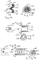
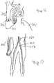
- the left view displays an amorphous, generally spherical embolism protection device 100 adjacent a catheter 102 within a vessel 104.
- the right hand view in Fig. 1 shows device 100 following expansion to fill the lumen of vessel 104.
- the arrow indicates a temporal advance over which device 100 swells across the lumen of vessel 104.
- device 100 has a random array of fibrous polymer forming the interior of the device 100.
- embolism protection device 110 has a cylindrical shape with a random interior polymer structure 112, as shown in Fig. 2 .
- device 110 has an outer surface covered with a fabric 114 excluding the flow ends through which the flow of the vessel passes.
- embolism protection device 120 has a generally cylindrical shape with a polymer matrix 122 that is approximately arranged on a grid.
- the outer surface of the cylinder is covered with fabric 124 with the ends of the cylinder exposed, i.e., free of the fabric. If fabric 124 has a sufficiently open weave, the fabric may also cover the ends of the cylindrical structure.
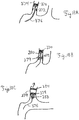
- embolism protection device 130 can have a concave shape along the direction of the flow.
- embolism protection device 130 has a generally bullet shape with the fluid flow oriented along arrow 132.
- Device 130 may or may not have a hollowed out interior along the concave surface.
- a saddle shaped embolism protection device 140 is shown in Figs. 5A and 5B .
- the direction of fluid flow is indicated by arrow 142.
- Device 140 has a convex central portion 144 with an outer collection portion 146.
- device 140 has a cuff 148, which for example can be formed from rolled fabric or other polymer material, for contacting the wall of vessel 104.
- a bioactive agent such as an thrombolytic agent, can be located at outer portion 146 for concentration at the location of emboli.
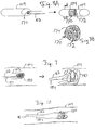
- embolism protection device 154 has an expandable outer section 156 that forms a hole 158 in the center upon expansion. This embodiment generally is intended to trap a larger embolism. While it is possible to design device 154 to provide some flow through outer section 156, generally this device is removed shortly following the capture of a larger embolism since flow can be significantly reduced due to the embolism. A variation on this embodiment is shown in Figs. 7A and 7B .
- embolism protection device 160 has polymer elements 162 that extend through a central core 164 within an outer ring 166. Polymer elements 162 create a filter that traps larger elements from the flow. Polymer elements may or may not swell upon contact with an aqueous solution, although outer ring 166 swell to expand to the wall of vessel 104.
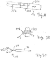
- embolism protection device 170 has a plurality of tubular shaped passages 172 along the length of the generally cylindrical device.
- the outer cylindrical surface 174 may or may not be covered in a fabric.
- the tubular shaped passages 172 can be formed from a collection of polymer tubes assembled together to form the structure or from tubular openings through a polymer matrix.
- embolism protection device 180 can comprise a tether or the like to facilitate removal of the device after sufficient time to protect against emboli.
- embolism protection device 180 comprises two strings 182, 184 that tether device 180, although a single string or greater than two strings can be used.
- Device 180 is shown in an unexpanded configuration in the left wide of Fig. 9 and in its expanded form in the right side of Fig. 9 . By providing two strings, pulling on the strings tends to draw the strings together to contract the device if the strings are in a spaced apart attachment on the device. As shown in Fig.
- strings 182, 184 are resulting in contraction in diameter of device 180 and corresponding movement from right to left.
- Other configurations of strings can be used to tether an embolism protection device to facilitate removal and to contract the device, which may depend on the particular shape and structure of the device.
- the embolism protection devices can comprise a composite of different structures, materials and/or bioactive agents.
- the embolism protection device can have identifiable portions that are compositionally distinct with respect to the average composition within the portion.
- the portions are positioned such that the flow or a substantial fraction of the flow passes sequentially through one section followed by another section. In such a configuration, generally at least about 25% of the flow volume and in other embodiments at least about 80% of the flow volume flow sequentially through the first portion followed by the second portion.
- embolism protection device 190 comprises an up-flow portion 192 and a down-flow portion 194, where flow through the vessel is indicated with arrow 196.
- up-flow portion 192 can elute, for example, a weak acid that tends to dissolve at least some emboli, while down-flow portion 194 can comprise a buffer that neutralizes the weak acid as it flows downstream.
- up-flow portion 192 and down-flow portion 194 can be separable.
- up-flow portion 192 can provide a mesh, a sponge-like material and/or another porous material across the flow to collect emboli for subsequent removal.
- Down-flow portion 194 can be a tubular structure that does not significantly alter the flow, but elutes a bioactive agent, such as tPA and/or NO. Since the portions separate, up-flow portion 192 can be taken from the vessel to remove the trapped emboli while down-flow portion remains in the vessel to elute beneficial agents.
- the positions of the two portions can be reversed with respect to the flow and the portion to be removed, i.e., the down-stream portion can be removed to leave the up-stream portion.
- the down-flow portion can also trap emboli.
- the down-flow portion can be effective to trap emboli.
- the down-flow portion can be formed from a bioresorbable material such that it dissolves at a desired rate.
- Figs. 1-11 are representative structures for the embolism protection device. Additional structures can be formed based on the disclosure herein.
- the embolism protection devices can be distributed along with other components that can be used along with other instruments that facilitate the use of the embolism protection device.
- an embolism protection device can be distributed along with delivery tools, retraction devices, tools for the delivery of biologically active agents, instructions and other suitable tools.
- Suitable delivery tools include, for example, sheaths and/or cannula into which the embolism protection device can be placed for delivery along with other catheter components that can facilitate the delivery of the device.
- Suitable retraction devices that facilitate the removal of the embolism protection device are described herein, which can be distributed with the embolism protection device.
- a guide-wire with a hollow core and/or a cannulated syringe can be distributed with the embolism protection device.
- the cannulated syringe can be connected to the guide-wire for the delivery of a biologically active agent in the vicinity of the embolism protection device within the patient's vessel.
- the guide-wire may or may not be associated with the embolism protection device as a tether.
- the embolism protection device can be distributed with instructions, which can take to form of written instructions and/or electronic copies, including, for example, a direction to a suitable web site.
- the commonly distributed elements can be distributed in one or more containers, for example, as a kit. While the embolism protection device generally is disposable following removal from the patient, the other individual elements distributed with the embolism protection device may or may not be reusable following sterilization.
- the embolism protection device can be fabricated from biocompatible materials, which can be delivered in vivo with limited vessel trauma, and, in some embodiments, can possess the ability to break down entrapped emboli. Some materials comprise a matrix, which can be capable in some embodiments of expanding upon delivery, capable of withstanding in vivo pressures to minimize movement and/or capable of delivering thrombolytic agents in a controlled fashion.
- the embolism protection devices described herein generally comprise one or more polymers with generally at least one polymer being an expandable polymer, e.g., swelling, shape adjusting and/or compressed, upon release in a vessel in a patient's body.
- Suitable polymers can be used for swelling including, for example, highly absorbing hydrophilic polymers (e.g., polyether-polyurethane) or hydrogels, while shape adjusting polymers can be memory polymers as described below.
- Compressed polymers are physically deformable or elastic such that they can be squeezed into a sheath or the like for delivery into a vessel of the patient, such that the polymer expands following removal from the sheath.
- the device comprises a plurality of polymers in a blend and/or a plurality of monomers in a copolymer, which can be a block copolymer.
- An advantage of using a plurality of polymers includes, for example, the ability to introduce properties characteristic of each individual polymer or of each monomer group incorporated into a copolymer.
- the expansion of the polymer and the corresponding device can occur spontaneously following the application of an appropriate stimulus.
- the appropriate stimulus can be, for example, contact with an aqueous fluid, release of constraining forces, such as applied by a sheath, and/or heating to body temperature.
- the expandable nature of at least some of the materials of the embolism protection devices inherently allows them to conform to the patient's vessel.
- minor variation in the vessel size and shape along the extent of the device can be handled appropriately by minor variations in the expansion of the device at different locations.
- the device shape can be formed specifically to adjust for delivery at the particular shape of the vessel. In these embodiments, the device expands into a predictable non-cylindrical shape due to the preshaping of the device.
- Suitable swelling polymers can include, for example, hydrogels and sponge materials.
- the amount of swelling that takes place upon contact with an aqueous medium can range from about 10 percent to greater than a factor of twenty times (i.e. 2000 percent), in some embodiments from a factor of fifty percent to a factor of fifteen times, in other embodiments from a factor of two times to a factor of twelve times, and in further embodiments from a factor of seven times to a factor of ten times.
- a person of ordinary skill in the art will recognize that addition ranges of swelling within the explicit ranges are contemplated and are within the present disclosure.
- the desired degree of swelling may be selected to provide the desired degree of pressure between the device and the vessel wall following deployment as well as accounting for the relative sizes of the vessel and the delivery device, such as a catheter.
- the device may further be compressible apart from the expansion from hydration such that release of the device from the delivery system results in an expanded device relative to its pre-delivery size.
- generally some swelling or other expansion is used to maintain the device within the vessel in which the swelling provides pressure against the vessel wall.
- the device contacts the wall over a significant portion of its outer surface such that the force against the vessel is distributed over a significant area. Since the force generally is spread over a significant area, the magnitude of the force can be correspondingly reduced such that there is less potential for damage to the vessel wall.
- the embolism protection device can be tethered in place such that little or no force is needed between the device and the vessel wall to hold the device at the delivered position.
- Hydrogels are hydrophylic polymers that generally are crosslinked to make them insoluble in an aqueous solution. Due to the hydrophylic nature of the polymer functional groups, the hydrogels draw aqueous solution into the polymer material.
- Suitable hydrogels include, for example, crosslinked forms of polyacrylamide, poly(hydroxyethylmethacrylate) (PHEMA), cellulose derivatives, poly(vinyl alcohol) and polyethylene glycol.
- PHEMA poly(hydroxyethylmethacrylate)
- cellulose derivatives poly(vinyl alcohol)
- polyethylene glycol polyethylene glycol.
- the degree of crosslinking, composition and other features can be used to control the degree of swelling. Some hydrogels can swell by a factor of 1000 percent or more upon contact with an aqueous solution. Several qualities of hydrogels have made them an attractive option in the medical deviqe arena.
- hydrogels are biocompatible, nontoxic, and nonthrombogenic, have inherent adhesiveness to tissue and have been shown to deliver drugs in a controlled fashion.
- the hydrogels can be used to associate with other polymers that are less biocompatible or more thrombogenic to introduce desirable properties to the composite.
- Suitable foam and sponge materials include, for example, polyester, aromatic vinyl polymers, polyether, polyurethane and mixtures thereof.
- Modified polyurethane polymers can be used to improve the biocomatability of the polymer. See, for example, U.S. Patent 6,320,011 to Levy et al. , entitled “Derivatized Polyurethane Compositions Which Exhibit Enhanced Stability In Biological Systems And Methods Of Making The Same”.
- the foam/sponge materials can be formed, for example, in a molding process with a blowing agent.
- An example of a polymeric sponge material and methods of forming the sponge material are described further in U.S. Patent 4,456,706 to Siedenstrang et al. , entitled “Molding compounds, Sponge Articles Produced Therefrom AndProcess Of Production”.
- Compressible biocompatible polymers include, for example, foam products useful for biological applications.
- foam products useful for biological applications For example, hydrophilic polyether-polyurethanes and polycarboxylate polyurethanes can be used to form foam that are compressible while absorbing a large amount of aqueous solutions.
- U.S. Patent 5,914,125 to Andrews et al. entitled “Wound Dressing,” describes a hydrophilic polyether polyurethane foam material with an adsorptive capacity of at least about 10 times its own weight.
- the embolism protection device can comprise a polymer blend and/or copolymer as other polymers alone may not provide all desired functions or properties. Specifically, it may be desirable to use at least one polymer to provide additional mechanical strength to the device within the flow and and an expanding polymer, such as a hydrogel, to introduce the expansion of the device upon delivery and to provide for control of the porosity of the expanded device.
- Suitable structural, biocompatible polymers for these blends include, for example, polyesters, such as polyethylene terephthalate, and polyurethanes, such as polycarbonate-polyurethanes, polyether polyurethanes, silicon-polyether-urethanes and silicon-polycarbonate-urethanes.
- these polymer blends comprises from about 25 weight percent to about 95 weight percent structural polymer relative to the total polymer of the blends, and in further embodiments from about 35 to about 85 weight percent structural polymer relative to the total polymer of the blends.
- a polymer blend generally would comprise at least about 40 weight percent expanding polymer and in other emboidments at least about 50 weight percent expanding polymer.
- the proportions can be considered with respect to the weight of blocks of a block copolymer.
- the embolism protection device can comprise a biodegradable shape adjusting or memory polymer. These polymer can transition to a memory shape upon application of a stimulus, such as a temperature change.
- a stimulus such as a temperature change.
- biodegradable polymers are available that resume a memory shape upon placement at body temperature or pH.
- the memory shape can be an expanded form that would extend the device across the lumen of the vessel.
- the memory polymer can expand the embolism protection device without the assistance of a swelling polymer, although the device may or may not comprise a blend or copolymer with the memory polymer and a hydrogel or other swelling polymer.
- Suitable memory polymers are described further in U.S. Patent 6,160,084 to Langer et al.
- the device with a biodegradable polymer can be combined with an initial amount of tPA and vectors to deliver an expressible tPA gene to transfect nearby cell to supply tPA on a longer term basis after the initial tPA with the device has eluted.
- the degradation of the device avoids the need to eventually remove the device and the supplies of tPA dissolve emboli such that the device does not become clogged with emboli during a more extensive implantation.
- suitable memory polymers include, for example, hydrophilic polymer fibers, including, for example, polyester fibers.
- Suitable fibers are described, for example, in U.S. Patent 5,200,248 to Thompson et al. , entitled "Open Capillary Channel Structures, Improved Process For Making Channel Structures And Extrusion Die For Use Therein". These fibers can be heated gently to cause the fibers to curl. The curled fibers can be stretched straight at room temperature. Upon heating to body temperature, the fibers resume the curled configuration. By using a bundle of the stretched fibers, the individual fibers of the bundle curl upon delivery due to body heat/hydration to form a fibrous filter mat that can entrap emboli within the fibrous network. The appropriate number of fibers for the bundle can be selected empirically to yield the desired packing density in the resulting mat and corresponding effective pore size.
- a graft copolymer is prepared by linking together two different polymers, for example, by way of chemical initiation (10) or radiation (11) in the form of ultra violet light, gamma or x-ray irradiation.
- a graft copolymer can exhibit properties closely related to the two parent compounds.
- Some copolymer embodiments harbor the tensile strength and biostability of polyethylene terephthalate and the super absorbent swelling of polyacrylamide.
- PET Polyethylene terephthalate
- the molecular formula for PET is H-[O-(CH 2 ) 2 -O-CO-(C 6 H 4 )-CO] n -R where R can be, for example, OH (Dacron®) or OCH 3 (terylene), and the chemistry and fiber manufacture is well worked out.
- R can be, for example, OH (Dacron®) or OCH 3 (terylene), and the chemistry and fiber manufacture is well worked out.
- the FDA has approved PET for such implants as fabric used in suture (temporary implant) or sewing rings for heart valves (permanent implant).
- PET is suitable as the base material for an embolism protection device.
- Polyacrylamide belongs to the class of hydrogels known as super absorbent polymers. These polymers swell in the presence of aqueous solutions and can increase to 1000 times their original size. (14) The ability of polyacrylamide to swell can contribute significantly to the efficacy of some embodiments of the device design proposed here. However, placing such a material in the vasculature involves appropriate control of swelling parameters to avoid vessel harm from excessive swelling. In addition, swelling can cause changes in polymer porosity. (30) A pore size that is too small may hinder blood cell flow, while a pore size that is too large may allow emboli to pass. The design of the device contributes significantly to porosity, however porosity associated with swelling can also contribute to the function of entrapping emboli.
- polyacrylamide is derived from acrylamide monomer units.
- the molecular formula is -[CH 2 CHCONH 2 -] n -.
- Polyacrylamide is a linear hydrogel which can react with many kinds of compounds to produce derivatives of polyacrylamide with many valuable properties such as flocculation, thickening and surface activity. (16,29) This reactivity allows for addition of functional groups, which may alter its physical properties.
- super absorbent polymers there is a group of special polyacrylamide copolymers called super absorbent polymers. (17,21) These polymer can absorb water ten to one-thousand fold of their original weight and, under certain pressure, do not dehydrate.
- super absorbant polymers are capable of delivering agents to the surrounding microenvironment, which is a quality useful for delivery of thrombolytic agents from corresponding devices.
- Super absorbent hydrogels are also further described in U.S. Patent 6,271,278 to Kinam et al. , entitled "Hydrogel Composites And Super Porous Hydrogel Composites Having Fast Swelling, High Mechanical Strength, And Superabsorbent Properties".
- polyacrylamide is approved by the FDA for use in medical adhesives.
- the FDA approval of the material together with its material properties makes polyacrylamide a suitable polymer and/or copolymer for use in the embolism protection devices described herein. Polyacrylamide has been used as a controlled release vehicle for anti-microbial agents.
- block copolymers can be used to introduce a stable form of a polymer blend in which the hydrogel is bonded to a structural polymer.
- the hydrogel can be grafted onto the structural polymer material based on knowledge in the art.
- polymeric materials have been grafted together using plasma, although other crosslinking approaches can similarly be used.
- a high-energy plasma technique generates active groups in the polymer, which facilitate the grafting of the second substrate to the first.
- the chemical composition of the two materials are complementary to this potential bonding and have been individually used to generate graft copolymers.
- This copolymer matrix has the potential to swell and develop significant porosity in a controllable fashion. This reaction results in the grafting of polyacrylamide onto the (PET) fibers. This grafting can be further or alternatively facilitated with ultraviolet crosslinking.
- (25) See Equation 1.
- the embolism protection device comprises a biodgradable/ bioresorbable polymers. These embodiments may or may not further comprise a biologically active agent that is released by the degradation of the biodegradable polymer following implantation within a patient.
- Suitable biodegradable polymers include, for example, polysaccharides, such as polydextran, cellulose and starch, hydroxyethyl starch, derivatives of gelatin, polyvinylpyrrolidone, polyvinyl alcohol, poly[N-(2-hydroxypropyl)methacrylamide], poly(hydroxyacids), poly(epsilon-caprolactone), polylactic acid, polyglycolic acid, poly(dimethyl glycolic acid), poly(hydroxybutyrate), copolymers thereof and mixtures thereof.
- the polymers during the crosslinking/grafting step can be molded into the desired form.
- Various molding techniques can be used, such as injection molding, casting, compression molding and the like.
- other polymer processing approaches can similarly be used, such as extrusion, calendering, blowing and the like.
- foam materials can be formed conveniently by extrusion, and composite materials can be formed by coextrusion.
- the porosity is introduced through a particulate pore forming agent that is combined with the polymer during processing and subsequently removed, such as by dissolving the particles while leaving the polymer intact, to leave the pores. The nature of the porosity is determines in part from the nature of the pore forming materials. If sponge-like materials are formed by foaming, non-uniform pressure can be applied to the expanding foam to change the resultant porosity.
- Biocompatible metals include, for example, titanium, titanium-nickel alloys, and stainless steel.
- Guidewires, tethers and the like can also be formed from these biocompatible metals and/or biocompatible fibers, which can be formed from the same materials as the biocompatible fabrics described below.
- the embolism protection device can further comprise a biocompatible adhesive, especially on the exterior of the device to facilitate anchoring of the device at the place of delivery.
- Suitable biocompatible adhesives include, for example, commercially available surgical adhesives, such as cyanoacralate (such as 2-octyl cyanoacrylate from Ethicon Products), fibrin glue (such as Tissucol® from Baxter) and mixtures thereof.
- surgical adhesives such as cyanoacralate (such as 2-octyl cyanoacrylate from Ethicon Products), fibrin glue (such as Tissucol® from Baxter) and mixtures thereof.
- the exterior can be covered with a biocompatible fabric.
- Biocompatible fabrics can be formed from a variety of materials, such as silk, nylon and/or polyesters, including, for example, Dacron® polyester.
- the fabric can be selected to have a porosity smaller than the porosity of at least a portion of the remaining device or no porosity, such that trapped emboli generally do not pass through the fabric upon the removal of the device from the patient.
- the embolism protection device can have a coating, such as a polymer coating, which can be formed by stray coating or dip coating a polymer solution or a polymer melt, which forms the polymer coating upon drying or cooling, respectively.
- Such a polymer coating may not be inherently porous, and desired porosity can be introduced by mechanically puncturing the coating with a fine needle or the like or by laser drilling appropriate pores.
- desired porosity can be introduced by mechanically puncturing the coating with a fine needle or the like or by laser drilling appropriate pores.
- lasers with moderate power can be used for the drilling and conventional optics can be used to focus the laser beam to produce the desired pore size.
- the embolism protection devices alone provide control over the movements of emboli within the patient's vessel. However, it may be desirable to combine the mechanical features of the device with biologically active agents to provide another dimension to the treatment.
- the association of bioactive agents with the device can both provide treatment to shrink or eliminate emboli within the device and/or also to deliver a bioactive agent downstream from the device.
- Suitable bioactive agents include, for example, thrombolytic (anti-thrombogenic) agents, anti-platelet agents, anti-coagulation agents, growth factors and combinations thereof.
- Suitable thrombolytic agents include, for example, tissue-type plasminogen activator (tPA), mutated forms of tPA, such as TNK-tPA and YM866, urokinase, streptokinase, staphylokinase, and the like.
- tPA tissue-type plasminogen activator
- mutated forms of tPA such as TNK-tPA and YM866
- urokinase such as TNK-tPA and YM866
- urokinase such as TNK-tPA and YM866
- urokinase such as TNK-tPA and YM866
- urokinase such as TNK-tPA and YM866
- urokinase such as TNK-tPA and YM866
- urokinase such as TNK-tPA and YM866
- urokinase such as TNK-tPA
- tPA refers to natural tPA, fragments thereof and analogs thereof that are effective to stimulate the formation of plasmin.
- an embolism protection device associated with tPA can be capable of destroying emboli associated with cardiopulmonary bypass.
- Recent reports suggest that most of the emboli generated during cardiopulmonary bypass have a significant fibrin component.
- the body's primary means of degrading fibrin is via tissue plasminogen activator (tPA).
- tPA tissue plasminogen activator
- tPA is currently in clinical use as a remedy for heart attack and stroke (thrombolysis, reperfusion therapy). This therapy involves delivering tPA through an intravenous line to break up and dissolve a clots in the coronary artery, thereby restoring blood flow.
- tPA is of particular interest for use with embolism protection devices described herein given its high specificity for clot degradation without causing systemic bleeding events.
- Suitable anti-platelet agents include, for example, acetylsalicylic acid, ADP inhibitors, phosphodiesterase III inhibitors, glycoprotein IIB/IIIA inhibitors, adenosine reuptake inhibitors, nitrates, such as nitroglicerin and isosorbide dinitrate, and Vitamin E.
- Suitable anti-coagulation agents include, for example, heparin, warfarin, and the like.
- Suitable growth factors include, for example, vascular endothelial growth factor (VEGF) and the like.
- materials are incorporated into the device that form by decomposition a therapeutic composition.
- nitric oxide can stimulate beneficial vascular responses.
- Compounds with an NONO - functional group can emit nitric oxide following implantation of the medical device.
- Suitable compositions include, for example, (CH 3 ) 2 CHNHNONO - , (CH 3 CH 2 ) 2 NNONO - , H 2 N(CH 2 ) 3 NHNONO - , NaNONONa.
- the bioactive agent can be associated with the materials of the embolism protection device by one or more approaches.
- the device can be contacted with a solution of the agent such that the agent can be infused within the device.
- the agent is then released, possibly gradually, upon implantation of the device.
- super absorbent polymers can be capable of delivering agents to the surrounding microenvironment, a quality appropriate for delivery of thrombolytic agents or other bioactive agents.
- the bioactive agents are placed in contact with the polymers during the polymerization and/or crosslinking/grafting steps such that the bioactive agents are incorporated within the polymer matrix. The bioactive agents then elute following implantation.
- the therapeutic dose of tPA for a human patient can be 0.01 to 80 micro moles (70-8750 ng/ml) but is thought to be most effective at 500-1000 ng/ml.
- Lower doses may be effective with local delivery since the local concentration can be higher over the delivery period.
- An appropriate corresponding dose for local delivery can be sustained throughout the time of implant. If the dose is released too quickly, a toxic environment can ensue (>25,000 ng/ml for systemic delivery).
- the release kinetics of tPA from the device can be used to deliver a desired dose of tPA or other biologically active agent.
- An empirical evaluation of an appropriate dose can be estimated from in vitro studies, such as the flow loop studies described below, or in animal studies.
- Suitable biocompatible carriers can be, for example, a physiologically buffered saline.
- Suitable buffers can be based on, for example, the following compounds: phosphate, borate, bicarbonate, carbonate, cacodylate, citrate, and other organic buffers such as tris(hydroxymethyl)aminomethane (TRIS), N-(2-hydroxyethyl) piparazine-N'-(2-ethanesulfonic acid) (HEPES) or morpholine propanesulphonic acid (MOPS).
- TMS tris(hydroxymethyl)aminomethane
- HEPES N-(2-hydroxyethyl) piparazine-N'-(2-ethanesulfonic acid)
- MOPS morpholine propanesulphonic acid
- the ionic strength of the biocompatible carrier can be adjusted by the addition of one or more inert salts including, for example, NaCl, KCl and combinations thereof. Preferably, the ionic strength is near physiological values.
- genes coding for desired polypeptide-bioactive agents can be delivered in a vector.
- the vector can be taken up by adjacent cells and expressed as the protein.
- Suitable vectors are known in the art, and include, for example, viral vectors, plasmids and the like.
- a vector encoding tPA can be delivered through the device. The effectiveness of a vector for tPA expression in rabbits is described further in Waugh et al., "Gene therapy to promote thromboresistance: Local over-expression of tissue plasminogen activator to prevent arterial thrombosis in an in vivo rabbit model, Proceeding of the National Academy of Sciences - USA 96(3): 1065-1070 (February 2, 1999 ).
- Vectors for example, plasmids and viral vectors, suitable for transforming human cells with appropriate control sequences for expression in human cells are described further in U.S. Patent 5,106,741 to Marotti et al. , entitled “Tissue Plasminogen Activator (TPA) Analogs," and U.S. Patent 4,935,368 to Ryotaro et al. , entitled “Process For Producing Tissue Plasminogen Activator”.
- TPA tissue Plasminogen Activator
- emboli generation frequently causes life altering, and possibly life threatening neurological disturbances.
- the emboli protection device described herein can be useful for all patients undergoing cardiac surgery and for other procedures.
- the elegant design employs a unique combination of FDA approved materials and therapeutic agents to provide an easy to use and effective means of controlling embolic events. At some point following the delivery of an embolism protection device, it may be desirable to remove the device or a portion thereof.
- embolism protection devices can be supplied to medical professionals in a range of sizes, such that an appropriate size can be selected from the available sizes for a particular patient and for a particular point of placement. Due to the expanding nature of the embolism protection device a precise size device is not required since the device conforms over a reasonable range to the vessel. Nevertheless, imaging techniques and estimates from experience and the patient's size can provide an appropriate estimate for the appropriate size of the embolism protection device.
- An embolism protection device can be placed within the desired vessel of a patient with a catheter, a syringe, a guidewire or the like. In particular, an embolism protection device can be attached to a guidewire to feed the device through a catheter to a desired position in a vessel within a patient.
- the guidewire can be separate from the device following the placement of the device, or the guidewire can remain tethered to the device to facilitate maintaining the device at the desired position and/or to facilitate removal of the device. Removal of the guidewire can be performed by pulling out the guidewire if the guidewire is not attached to the device and if the device is applying sufficient force against the walls of the vessel such that friction can hold the device in place. If the guidewire is to remain attached to the device, the guidewire can be attached to the device with a mechanical attachment or with an adhesive.
- the guidewire can be mechanically attached to the device, for example, by forming the polymer around the end of the wire, generally with a non-straight section of wire, winding the wire around a section of the device and/or heat strinking a portion of the polymer around the end of the wire.
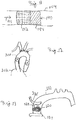
- the embolism protection device can be positioned at one or more positions within the aorta or in arteries branching from the aorta.
- aorta 200 is shown adjacent heart 202.
- five embolism protection devices 204, 206, 208, 210, 212 are shown in different positions. Any one or more of these can be used for a particular patient.
- Devices 204-212 are shown with device 204 in the ascending aorta, device 206 in the descending aorta, device 208 in the innominate artery, device 210 in the left common carotenoid artery and device 212 in the left subclavian artery.
- an embodiment is shown that is appropriate for use when the heart is on bypass.
- this device can be placed in the aorta distal to the site of cross clamp in a cardiac surgical procedure involving cardiopulmonary bypass.
- an embolism protection device 220 is within the ascending aorta 222 distal to cross clamp 224 and is attached to an aortic cannula 226, for example, with a fastener 228, such as a loop of material, a clip, anchor, a catching device or the like.
- An aortic cannula generally can be used to return blood to the heart when the heart is on bypass.
- the heart can be placed on bypass during a procedure to repair portions of the heart.
- Aortic cannula are known in the art, and one embodiment is described in U.S. Patent 6,387,087 to Grooters , entitled "Aortic Cannula". Attachment to aortic cannula 226 stabilizes device 220 at the pressures experienced during the cross clamp procedure. Referring to Fig. 14 , release of cross clamp 224 can result in the corresponding release of emboli 230 that are trapped by embolism protection device 220. Device 220 can release bioactive agents to dissolve emboli 230, and, additionally or alternatively, removal of device 220 can remove trapped emboli. For example, device 220 can be removed from the cannula site shortly following the removal of the cannula.
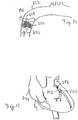
- an embolism protection device can be placed within a coronary artery.
- the embolism protection device can be placed down stream from a planned site of intervention, for example, by angioplasty, placement of a bypass graft or introduction of a stent.
- embolism protection device 240 is shown within coronary artery 242 of heart 244. Device 240 is located downstream in the artery from an intervention site 246.
- an embolism protection device can be place in the venous side of the heart/vascular system to prevent emboli to the lungs.
- embolism protection device 250 is within the pulmonary artery 252 downstream from the pulmonary heart valve 254 where pulmonary artery 252 attached to heart 256. Flow from the pulmonary artery goes to the lungs.
- an embolism protection device can be placed within any vessel in the body.
- devices 260, 262 are within arteries leading to the leg from the descending abdominal aorta 264 while device 266 is in an arm. Embolism protection devices can be similarly placed in veins.
- the embolism protection device can comprise two distinct portions or similarly can be used with a separate but associated drug delivery article.
- Use of such devices in the context of the application of a stent is shown in Figs. 18A, 18B and 18C .
- a two component embolism protection device 270 is placed downstream from a plaque deposit 272 in vessel 274.
- device 270 comprises a tether 276 to facilitate removal, although other removal approaches can be used.
- a stent 278 has been applied to plaque deposit 272 with the potential generation of emboli 280, which are trapped by embolism protection device 270.
- an embolism trapping portion 282 of device 270 is being removed using tether 276, while a bioactive agent eluting portion 284 of device 270 remains in vessel 274.
- one or more bioactive agents can be delivered through a guidewire or the like tethered to the embolism protection device.
- the guidewire can have a small inner channel that has an opening into the vessel at or near the proximal end. The flow rate and time determines the dose of biologically active agent delivered into the vessel.
- embolism protection device 300 associated with guidewire 302 is within a body vessel 304.
- Guidewire 302 has a small internal channel that can have an opening at point A, B and/or C.
- the natural flow direction in the vessel is indicated by arrow 306.
- Delivery of a biologically active agent at point A results in the flow of the agent through device 300 and downstream. Delivery of the agent at point B results in a concentration of the agent within the device with any residual agent flowing downstream. In addition, delivery of the agent at point C results in delivery of the agent downstream from the device.
- the embolism protection device may be desirable to remove the device or a portion thereof. For example, shortly after completing a procedure, the device may have had the opportunity to collect and/or dissolve the emboli of significance. Alternatively, once the embolism protection device has completed eluting a biologically active agent following the trapping and/or dissolving of emboli associated with a procedure or other event, it may be desirable to remove the device. Removal of the device can take place, for example, minutes, hours, days, months or years following delivery depending on the particular device and its intended purpose.
- an embolism protection device can be attached to one or more tethers or the like such that pulling on the tethers tends to reduce the size of the device such that it can be moved upstream from its delivered position.
- an embolism protection device can have a reduced diameter or pointed tip at the proximal end. With a reduced diameter proximal end and a compressible polymer structure generally possessed by the device, the device can be pulled within a sheath using a tether due to the forces applied to the device at the end of the sheath. Once the device is confined within the sheath, the device can be withdrawn from the vessel with the sheath.
- an extraction device can be used to facilitate removal of the embolism protection device.
- An extraction device comprises a gripper that can grip the embolism protection device and reduce the diameter of at least a portion thereof.
- the gripper can be positioned within the vessel through a catheter or the like.
- An actuating wire or other control device can connect the gripper with a control handle at the proximal end of the gripper device outside of the patient.
- the gripper can be manipulated by a health care professional from outside of the patient using appropriate visualization techniques, such as a fiber optic based visualization systems for minimally invasive surgical procedures.
- Gripper 310 has a gripping portion with four flexible arms 312 extending from a shaft 314.
- Shaft 314 can have a hollow core for threading the shaft over a guide-wire or the like.
- An outer shaft 316 can move in position relative to shaft 314.
- Outer shaft 316 can engage arms 312 and deflect them toward the center of shaft 314. This deflection of arms 312 results in a gripping function.
- arms 312 are positioned along the outer surface of an embolism protection device, the deflection of arms 312 toward a center axis compresses the embolism protection device correspondingly.
- gripper 310 can be used to facilitate removal of a portion of the embolism protection device oriented toward the gripper.
- various other gripper configurations including, for example, some configurations developed for use with catheters for other functions can be adapted for use in removing an embolism protection device.
- This example demonstrates the synthesis of a polyacrylamide hydrogel polymer grafted onto a PET polyester polymer.
- the plasma glow discharge system primarily consisted of a barrel radio frequency (RF) plasma reactor with a diameter and depth of six inches (Extended Plasma Cleaner, Harrick Scientific, Ossining, NY). The pressure was monitored by a thermocouple vacuum gauge (Hastings Vacuum Gauge, DV-6). The reaction chamber was evacuated to 1.333 Pa (10 millitorr (mtorr)) to remove contaminants and moisture. The chamber was then flooded with research grade oxygen gas (99.99%), and evacuated until a constant pressure of 20Pa(150 mtorr) was established, at which point RF plasma of 30Watt was applied for ten minutes.
- RF radio frequency
- Activated fibers were then dip coated with a mixture of polyacrylamide (10% by weight (wt)), acrylamide monomer (10%-20% by wt), and methylenebis-acrylamide (0.05-0.1% by wt crosslinker) and a UV sensitive initiator in water. The grafting was allowed to cure under a UV lamp for 10 minutes.
- This example demonstrates the incorporation of tPA into a polyacrylamide (PAM) polymer and the subsequent release of the tPA.
- tPA was incorporated into a polyacrylamide hydrogel by dispersion into the polymerization solution at the time of polymerization. This method may result in the entrapment of the tPA in the interstices of the gel-like matrix where it is held until hydration at which time the agent is slowly released.
- a 2.8 ml solution was prepared comprising 1.5 ml- 5 weight % acrylamide solution (approximate final concentration based on a volume per volume dilution 2.67% acrylamide), 6 ⁇ l- human two-chain tPA (2.2 mg/ml, from Molecular Sciences, MI), 9 ⁇ l-10% ammonium persulfate, 2.25 ⁇ l- TEMED (N,N,N',N'-tetramethylenediamine, 99% solution) and deionized water.
- the ammonium persulfate produces free radicals faster in the presence of TEMED such that the addition of TEMED to the mixture accelerates the polymerization and crosslinking of the gel.
- the release kinetics of the tPA was analyzed. After polymerization, the gels were carefully removed from the test tubes and put in 20ml vials. The test tube was rinsed with 5ml of phosphate buffered saline (PBS), and the rinse poured over the gel in the 20ml vial. This was slightly shaken to rinse the gel and to remove any unincorporated tPA. A 50 ⁇ l quantity of this solution was frozen. The remainder was poured off and replaced with another 5ml of PBS. Both the gels and the controls were kept at 4°C for the release experiment in an effort to prevent protein degradation and slightly shaken on an oscillating shaker. At designated time points, 50 microliter ( ⁇ l) aliquots of buffer were taken.
- PBS phosphate buffered saline
- tPA The amount of tPA in each aliquot was determined via ELISA (Diapharma Group, Inc. Westchester, Ohio). In brief, buffer samples were transferred in 100 ⁇ l volumes to wells of a 96-well plate containing anti-tPA IgG. The samples were incubated for 2 hours at room temperature. Bound tPA was detected with HRP (horseradish peroxidase) - labeled Fab fragments of anti-tPA IgG followed by a peroxidase substrate. Colorimetric staining was detected and actual quantity determined via comparison to the included standards (Biopool International, Cat#101-442).
- Fig. 23 shows the standard curve for the tPA ELISA. The curve was linear over the range tested with an R-squared value of 0.978.
- Fig. 23 is a plot of the experimentally measured time release kinetics of tPA from the hydrogel. Release of tPA from the hydrogel reached a maximum release of 31.4 ng/ml at 60 minutes.
- a PET:PAM copolymer matrix This matrix can be produced such that swelling is rapid, sustained and reproducible.
- tPA can be incorporated into the matrix.
- the release rate is typical of a hydrogel with an initial quick release sustained for at least 60 minutes following test initiation. This time duration would be sufficient for post-cardiopulmonary bypass cross-clamp embolism protection device filtration time, however further crosslinking alterations can be made to alter release. This release can be tailored after the toxic dose parameters and dose necessary for emboli destruction are determined.
- This example demonstrates the effectiveness of recombinant human Tissue Plasminogin Activator (tPA) as a resolving agent with respect to the dissolution of porcine thrombolytic emboli in vitro.
- tPA Tissue Plasminogin Activator
- tPA was diluted in phosphate buffered saline at the following concentrations: 1,000 nanograms/milliliter (ng/ml), 500 ng/ml, 100 ng/ml and 0 ng/ml.
- the emboli dissolution potential of each tPA solution was measured by applying the tPA solution to glass slides containing emboli and then measuring the change in emboli size as a function of time.
- coagulated porcine whole blood was placed in a 5cc syringe. Coagulated blood was extruded from the syringe and cut to uniform size (200-225 ⁇ m diameter); these uniform coagulated blood fragments will be referred to as "emboli”.
- Emboli were placed on glass slides for microscopic measurement. Samples were labeled and measurement/descriptions were made for each embolus. Measurement was accomplished with a Zeiss® Microscope and Zeiss® LSM 4 software for image acquisition. One ml quantities of tPA solution were added to the characterized emboli and then placed on a shaker at 20 RPM in a testing room at 30-35°C.
- This example demonstrates the utility of an in vitro flow loop for evaluation of an embolism protection device as well as provides an evaluation of two embodiments of an embolism protection device, one with tPA and one without tPA.
- the interrupted flow loop was developed to mimic the environment of a native coronary artery.
- the apparatus consisted of four components: a circulation unit, the embolism protection device, the blood/media, and the emboli.
- the flow loop was constructed as indicated in Fig. 24 .
- the circulation unit had a heated reservoir 350 holding blood and media 352, tubing 354, a pump 356, injection ports 358, 360 and a collection vessel 362.
- Embolism protection device 364 was held in a fixture 366 within tubing 354. Flow through the system is noted in Fig. 24 with four flow arrows.
- Embolism protection device 364 was formed with two sections of structure.
- the layered system for purposes of this experiment was a polymeric construct that could both release tPA and trap the emboli based on an appropriate porosity.
- a first layer 380 was a nylon mesh polymer with a 70 micron pore diameter obtained from Sefar America Inc. Depew, NY. Layer 380 served to entrap emboli.
- a second layer 382 was a sponge-like layer made of polyacrylamide and impregnated with tPA.
- tPA tPA into layer 382
- a solution was prepared comprising of 1.5 ml- 5 weight % acrylamide solution (approximately 2.67% acrylamide final concentration based on a volume per volume dilution), 6 ⁇ l- human single-chain tPA (2.2 mg/ml, Molecular Sciences, MI), 9 ⁇ l- 10% ammonium persulfate and 6.7 ⁇ l- TEMED.
- Three aliquots of 0.5 ml gels were made in glass test tubes and allowed to polymerize for 1hr at room temperature, thus creating three gels. Following polymerization, each gel had a total TPA amount of 500 ng at a concentration of 1,000 ng/ml).
- the gels were removed from the tubes, and the nylon mesh layer was wrapped around the flat end and the sides of each gel leaving the rounded end of the gel from the bottom of the tube uncovered with the mesh.
- Each device when placed within the flow loop was positioned with the flat end down-stream and with the round end upstream such that emboli are trapped by the mesh within the gel.
- the gel expands to approximately twice its volume, as is schematically shown in Fig. 27 , while the nylon mesh remains essentially unchanged, although it expands in response to the expansion of the gel. Due to the expansion of the gel, the pore size of the mesh may enlarge, but this enlargement was not directly measured.
- test fixture 366 has two rings 368, 370 held together with a joining ring 372. Edges of device 364 are gripped between rings 368, 370 to fix device 364 in place.
- Circulation of the media was performed with a centrifugal pump capable of generating flows from 30-120 ml/min.
- the tubing was a vinyl polymer with an inner diameter from 4-6 mm, similar to that of the native arterial vessels.
- the experiment was accomplished in a test chamber at 37°C.
- Injection port 358 upstream from the embolism protection device was used to introduce the test emboli.
- the medium flowing through the system was phosphate buffered saline.
- Emboli were generated by placing 1ml of pig animal blood in a syringe and allowing it to clot (see above for determination of emboli size). The flow loop was validated using a calibrated flowmeter.
- the emboli were introduced into the flow system at a concentration of approximately 15 emboli/ml of buffered saline.
- the time line for the testing was as follows:
- the PBS was collected.
- the total collected effluent was passed over a 0.22 ⁇ m filter, and the filter was analyzed via light microscopy for presence of emboli.
- the effluent had no observable emboli after passing through any of the six devices. This demonstrated that the devices were effective to trap the emobli without blocking the flow.
- embolism protection device was frozen and paraffin embedded for histological archiving. Selected samples were sectioned and prepared for immunohistochemistry as follows. Sections were postfixed for 2 minutes in 100 mmol/L tris-buffered 1% paraformaldehyde containing 1 mmol/L EDTA, pH 7.2, and rinsed with three changes of phosphate buffered saline, pH 7.2.
- Porcine fibrin decomposition via tPA thrombolysis was detected using murine antibodies specific for neotype beta-chain fibrin (Mouse Anti-Human, Cross-reacts with pig, American Diagnostica, Inc., Greenwich, CT, Cat 350, 1:100 dilution, rhodamine conjugated, monoclonal IgG-1) and CD41 platelet glycoprotein IIa/IIIb (Mouse Anti-Human, Cross-reacts with pig, DakoCytomation, Carpinteria, CA, Cat M7057, 1:100 dilution, FITC conjugated, monoclonal IgG-1).
- the antibodies listed above were diluted in phosphate buffered saline containing 5% bovine serum albumin (Sigma Chemical Co.) and applied to sections for 30 minutes. Then, the section was rinsed with phosphate buffered saline. All sections were cover-slipped with a 1:8 dilution of Vectashield-DAPI (4,6-diamidino-2-phenylindole) in phosphate buffered saline (Vector Laboratories) and evaluated using an epifluorescence microscope.
- phosphate buffered saline containing 5% bovine serum albumin (Sigma Chemical Co.)
- All sections were cover-slipped with a 1:8 dilution of Vectashield-DAPI (4,6-diamidino-2-phenylindole) in phosphate buffered saline (Vector Laboratories) and evaluated using an epifluorescence microscope.
- Figs. 29A and 29B are fibrin recovered from the embolism protection device releasing tPA, while Figs. 4C and 4D show fibrin at the same magnification recovered from an embolism protection device not releasing tPA.
- fibrin treated with tPA was dissolved away to remove significant portions of the structure and to leave relatively large pores in comparison with the equivalent fibrin in Figs. 29C and 29D that was not treated with tPA.
Claims (11)
- Dispositif de protection contre l'embolie constitué d'un polymère expansible biocompatible, dans lequel le polymère expansible se dilate au moment de la libération au sein d'un vaisseau d'un patient en une structure configurée pour filtrer un écoulement à travers le vaisseau et remplissant la lumière du vaisseau, dans lequel le dispositif a un ensemble aléatoire de polymère fibreux formant l'intérieur du dispositif.
- Dispositif de protection contre l'embolie selon la revendication 1, dans lequel le polymère expansible comprend un hydrogel.
- Dispositif de protection contre l'embolie selon la revendication 1, dans lequel le polymère expansible comprend un polymère à mémoire.
- Dispositif de protection contre l'embolie selon l'une quelconque des revendications 1 à 3 comprenant un copolymère séquencé.
- Dispositif de protection contre l'embolie selon l'une quelconque des revendications 1 à 4, dans lequel le dispositif se dilate à raison d'au moins environ 50 pour cent en volume.
- Disposition de protection contre l'embolie selon l'une quelconque des revendications 1 à 5, dans lequel à la suite d'une dilatation le dispositif a une porosité pour bloquer le passage d'une majorité substantielle de particules avec un diamètre d'au moins environ 0,1 millimètre et permet l'écoulement à travers le dispositif d'une majorité substantielle de particules avec un diamètre de pas plus d'environ 0,01 millimètre.
- Dispositif de protection contre l'embolie selon l'une quelconque des revendications 1 à 6 comprenant en outre un agent biologiquement actif qui s'élue du dispositif lorsqu'il est en contact avec l'écoulement dans un vaisseau du patient.
- Dispositif de protection contre l'embolie selon la revendication 7, dans lequel l'agent biologiquement actif comprend le tPA.
- Système pour piéger des embolies comprenant un outil de distribution et un dispositif de protection contre l'embolie selon les revendications 1 à 8.
- Système selon la revendication 9, où le système comprend en outre un fil guide.
- Système selon la revendication 9, dans lequel l'outil de distribution comprend une canule à travers laquelle le dispositif de protection contre l'embolie peut être distribué.
Applications Claiming Priority (5)
| Application Number | Priority Date | Filing Date | Title |
|---|---|---|---|
| US414909 | 1989-09-29 | ||
| US40034102P | 2002-08-01 | 2002-08-01 | |
| US400341P | 2002-08-01 | ||
| US10/414,909 US7303575B2 (en) | 2002-08-01 | 2003-04-16 | Embolism protection devices |
| PCT/US2003/024459 WO2004012587A2 (fr) | 2002-08-01 | 2003-08-01 | Dispositifs de protection contre l'embolie |
Publications (3)
| Publication Number | Publication Date |
|---|---|
| EP1545322A2 EP1545322A2 (fr) | 2005-06-29 |
| EP1545322A4 EP1545322A4 (fr) | 2008-12-03 |
| EP1545322B1 true EP1545322B1 (fr) | 2019-10-02 |
Family
ID=31498612
Family Applications (1)
| Application Number | Title | Priority Date | Filing Date |
|---|---|---|---|
| EP03767200.3A Expired - Lifetime EP1545322B1 (fr) | 2002-08-01 | 2003-08-01 | Dispositifs de protection contre l'embolie |
Country Status (5)
| Country | Link |
|---|---|
| US (2) | US7303575B2 (fr) |
| EP (1) | EP1545322B1 (fr) |
| JP (1) | JP2005534429A (fr) |
| AU (1) | AU2003257182A1 (fr) |
| WO (1) | WO2004012587A2 (fr) |
Families Citing this family (153)
| Publication number | Priority date | Publication date | Assignee | Title |
|---|---|---|---|---|
| US7790192B2 (en) | 1998-08-14 | 2010-09-07 | Accessclosure, Inc. | Apparatus and methods for sealing a vascular puncture |
| US7314477B1 (en) | 1998-09-25 | 2008-01-01 | C.R. Bard Inc. | Removable embolus blood clot filter and filter delivery unit |
| US6402771B1 (en) | 1999-12-23 | 2002-06-11 | Guidant Endovascular Solutions | Snare |
| US6660021B1 (en) | 1999-12-23 | 2003-12-09 | Advanced Cardiovascular Systems, Inc. | Intravascular device and system |
| US6575997B1 (en) | 1999-12-23 | 2003-06-10 | Endovascular Technologies, Inc. | Embolic basket |
| US7918820B2 (en) | 1999-12-30 | 2011-04-05 | Advanced Cardiovascular Systems, Inc. | Device for, and method of, blocking emboli in vessels such as blood arteries |
| US6695813B1 (en) | 1999-12-30 | 2004-02-24 | Advanced Cardiovascular Systems, Inc. | Embolic protection devices |
| US6964670B1 (en) | 2000-07-13 | 2005-11-15 | Advanced Cardiovascular Systems, Inc. | Embolic protection guide wire |
| US6506203B1 (en) | 2000-12-19 | 2003-01-14 | Advanced Cardiovascular Systems, Inc. | Low profile sheathless embolic protection system |
| US7338510B2 (en) | 2001-06-29 | 2008-03-04 | Advanced Cardiovascular Systems, Inc. | Variable thickness embolic filtering devices and method of manufacturing the same |
| US6599307B1 (en) | 2001-06-29 | 2003-07-29 | Advanced Cardiovascular Systems, Inc. | Filter device for embolic protection systems |
| US6638294B1 (en) | 2001-08-30 | 2003-10-28 | Advanced Cardiovascular Systems, Inc. | Self furling umbrella frame for carotid filter |
| US6592606B2 (en) | 2001-08-31 | 2003-07-15 | Advanced Cardiovascular Systems, Inc. | Hinged short cage for an embolic protection device |
| US8262689B2 (en) | 2001-09-28 | 2012-09-11 | Advanced Cardiovascular Systems, Inc. | Embolic filtering devices |
| US7241304B2 (en) | 2001-12-21 | 2007-07-10 | Advanced Cardiovascular Systems, Inc. | Flexible and conformable embolic filtering devices |
| US9204956B2 (en) | 2002-02-20 | 2015-12-08 | C. R. Bard, Inc. | IVC filter with translating hooks |
| US7303575B2 (en) * | 2002-08-01 | 2007-12-04 | Lumen Biomedical, Inc. | Embolism protection devices |
| US7331973B2 (en) | 2002-09-30 | 2008-02-19 | Avdanced Cardiovascular Systems, Inc. | Guide wire with embolic filtering attachment |
| US7252675B2 (en) | 2002-09-30 | 2007-08-07 | Advanced Cardiovascular, Inc. | Embolic filtering devices |
| US20040088000A1 (en) | 2002-10-31 | 2004-05-06 | Muller Paul F. | Single-wire expandable cages for embolic filtering devices |
| US8591540B2 (en) | 2003-02-27 | 2013-11-26 | Abbott Cardiovascular Systems Inc. | Embolic filtering devices |
| US7879062B2 (en) * | 2003-07-22 | 2011-02-01 | Lumen Biomedical, Inc. | Fiber based embolism protection device |
| US8048042B2 (en) * | 2003-07-22 | 2011-11-01 | Medtronic Vascular, Inc. | Medical articles incorporating surface capillary fiber |
| US20070135907A1 (en) | 2003-10-02 | 2007-06-14 | The Regents Of The University Of California | Stent with expandable foam |
| US7892251B1 (en) | 2003-11-12 | 2011-02-22 | Advanced Cardiovascular Systems, Inc. | Component for delivering and locking a medical device to a guide wire |
| US20050107867A1 (en) * | 2003-11-17 | 2005-05-19 | Taheri Syde A. | Temporary absorbable venous occlusive stent and superficial vein treatment method |
| EP1557128B1 (fr) * | 2004-01-23 | 2007-03-07 | Cathenet Corporation | Dispositif d'athérectomie |
| US8092483B2 (en) | 2004-03-06 | 2012-01-10 | Medtronic, Inc. | Steerable device having a corewire within a tube and combination with a functional medical component |
| US7678129B1 (en) | 2004-03-19 | 2010-03-16 | Advanced Cardiovascular Systems, Inc. | Locking component for an embolic filter assembly |
| US7976516B2 (en) * | 2004-06-25 | 2011-07-12 | Lumen Biomedical, Inc. | Medical device having mechanically interlocked segments |
| US20060020269A1 (en) * | 2004-07-20 | 2006-01-26 | Eric Cheng | Device to aid in stone removal and laser lithotripsy |
| US7704267B2 (en) | 2004-08-04 | 2010-04-27 | C. R. Bard, Inc. | Non-entangling vena cava filter |
| US20060047301A1 (en) * | 2004-09-02 | 2006-03-02 | Ogle Matthew F | Emboli removal system with oxygenated flow |
| US7927346B2 (en) * | 2004-09-10 | 2011-04-19 | Stryker Corporation | Diversion device to increase cerebral blood flow |
| US8262693B2 (en) * | 2004-11-05 | 2012-09-11 | Accessclosure, Inc. | Apparatus and methods for sealing a vascular puncture |
| US7794473B2 (en) | 2004-11-12 | 2010-09-14 | C.R. Bard, Inc. | Filter delivery system |
| EP1681068A1 (fr) * | 2004-12-16 | 2006-07-19 | NOLabs AB | Dispositif de filtration à élution de monoxyde d'azote |
| WO2006064056A2 (fr) * | 2004-12-16 | 2006-06-22 | Nolabs Ab | Dispositif et procedes de filtrage anti-elements pathogenes ou cancereux faisant appel a de l'oxyde nitrique |
| US20060161241A1 (en) * | 2005-01-14 | 2006-07-20 | Denise Barbut | Methods and devices for treating aortic atheroma |
| EP1841368B1 (fr) * | 2005-01-25 | 2015-06-10 | Covidien LP | Structures pour l'occlusion permanente d'une structure anatomique creuse |
| US8267954B2 (en) | 2005-02-04 | 2012-09-18 | C. R. Bard, Inc. | Vascular filter with sensing capability |
| US8945169B2 (en) * | 2005-03-15 | 2015-02-03 | Cook Medical Technologies Llc | Embolic protection device |
| US9259305B2 (en) | 2005-03-31 | 2016-02-16 | Abbott Cardiovascular Systems Inc. | Guide wire locking mechanism for rapid exchange and other catheter systems |
| US20060224178A1 (en) * | 2005-04-05 | 2006-10-05 | Boston Scientific Scimed, Inc. | Expandable medical retrieval device and related methods of use |
| CA2607580C (fr) | 2005-05-12 | 2016-12-20 | C.R. Bard Inc. | Filtre amovible pour caillot sanguin ou embole |
| US20080172066A9 (en) * | 2005-07-29 | 2008-07-17 | Galdonik Jason A | Embolectomy procedures with a device comprising a polymer and devices with polymer matrices and supports |
| CA2616818C (fr) | 2005-08-09 | 2014-08-05 | C.R. Bard, Inc. | Filtre pour caillots de sang generateurs d'embolie et systeme de mise en place |
| US20070112372A1 (en) * | 2005-11-17 | 2007-05-17 | Stephen Sosnowski | Biodegradable vascular filter |
| EP1948074A2 (fr) | 2005-11-18 | 2008-07-30 | C.R.Bard, Inc. | Filtre de veine cave avec filament |
| US8052714B2 (en) | 2005-11-22 | 2011-11-08 | Medtronic Vascular, Inc. | Radiopaque fibers and filtration matrices |
| EP1954341A2 (fr) * | 2005-12-02 | 2008-08-13 | C.R.Bard, Inc. | Filtre helicoidal de veine cave |
| WO2007090130A2 (fr) * | 2006-01-30 | 2007-08-09 | Surgica Corporation | Particules d'embolisation intravasculaire et procedes associes |
| EP1986707A2 (fr) * | 2006-01-30 | 2008-11-05 | Surgica Corporation | Particules d'embolisation intravasculaire compressible, procedes connexes et systemes d'administration |
| US20070185520A1 (en) * | 2006-02-07 | 2007-08-09 | Boston Scientific Scimed, Inc. | Detachable medical immobilization device and related methods of use |
| US20070203564A1 (en) * | 2006-02-28 | 2007-08-30 | Boston Scientific Scimed, Inc. | Biodegradable implants having accelerated biodegradation properties in vivo |
| US8795709B2 (en) | 2006-03-29 | 2014-08-05 | Incept Llc | Superabsorbent, freeze dried hydrogels for medical applications |
| US7846175B2 (en) | 2006-04-03 | 2010-12-07 | Medrad, Inc. | Guidewire and collapsable filter system |
| US9017361B2 (en) | 2006-04-20 | 2015-04-28 | Covidien Lp | Occlusive implant and methods for hollow anatomical structure |
| WO2007133366A2 (fr) | 2006-05-02 | 2007-11-22 | C. R. Bard, Inc. | Filtre à veine cave formé à partir d'une feuille |
| US20100030251A1 (en) * | 2006-05-24 | 2010-02-04 | Mayo Foundation For Medical Education And Research | Devices and methods for crossing chronic total occlusions |
| WO2007143602A2 (fr) | 2006-06-05 | 2007-12-13 | C.R. Bard Inc. | Filtre pour caillots sanguins générateurs d'embolie utilisable avec un système de mise en place unique ou un système de retrait unique via un accès fémoral ou jugulaire |
| EP3338735A1 (fr) * | 2006-07-19 | 2018-06-27 | Novate Medical Limited | Filtre vasculaire |
| US8460335B2 (en) | 2006-09-11 | 2013-06-11 | Embrella Cardiovascular, Inc. | Method of deflecting emboli from the cerebral circulation |
| US9339367B2 (en) | 2006-09-11 | 2016-05-17 | Edwards Lifesciences Ag | Embolic deflection device |
| US9480548B2 (en) | 2006-09-11 | 2016-11-01 | Edwards Lifesciences Ag | Embolic protection device and method of use |
| US20080085294A1 (en) * | 2006-10-04 | 2008-04-10 | Toby Freyman | Apparatuses and methods to treat atherosclerotic plaques |
| US8216209B2 (en) | 2007-05-31 | 2012-07-10 | Abbott Cardiovascular Systems Inc. | Method and apparatus for delivering an agent to a kidney |
| US7867273B2 (en) | 2007-06-27 | 2011-01-11 | Abbott Laboratories | Endoprostheses for peripheral arteries and other body vessels |
| US20090069790A1 (en) * | 2007-09-07 | 2009-03-12 | Edward Maxwell Yokley | Surface properties of polymeric materials with nanoscale functional coating |
| US8962097B1 (en) | 2007-09-07 | 2015-02-24 | Edward Maxwell Yokley | Surface properties of polymeric materials with nanoscale functional coating |
| US9138307B2 (en) | 2007-09-14 | 2015-09-22 | Cook Medical Technologies Llc | Expandable device for treatment of a stricture in a body vessel |
| US9034007B2 (en) | 2007-09-21 | 2015-05-19 | Insera Therapeutics, Inc. | Distal embolic protection devices with a variable thickness microguidewire and methods for their use |
| JP2011502582A (ja) | 2007-11-02 | 2011-01-27 | インセプト,エルエルシー | 血管穿刺を塞ぐ装置および方法 |
| US8636670B2 (en) | 2008-05-13 | 2014-01-28 | The Invention Science Fund I, Llc | Circulatory monitoring systems and methods |
| US20090287120A1 (en) | 2007-12-18 | 2009-11-19 | Searete Llc, A Limited Liability Corporation Of The State Of Delaware | Circulatory monitoring systems and methods |
| US9717896B2 (en) | 2007-12-18 | 2017-08-01 | Gearbox, Llc | Treatment indications informed by a priori implant information |
| US20100152646A1 (en) * | 2008-02-29 | 2010-06-17 | Reshma Girijavallabhan | Intravitreal injection device and method |
| JP5391407B2 (ja) * | 2008-04-03 | 2014-01-15 | クック・メディカル・テクノロジーズ・リミテッド・ライアビリティ・カンパニー | 自浄式装置、システムおよびその使用方法 |
| WO2010008451A2 (fr) | 2008-06-23 | 2010-01-21 | Lumen Biomedical, Inc. | Protection embolique durant le remplacement percutané de valvules cardiaques et des interventions similaires |
| US8070694B2 (en) | 2008-07-14 | 2011-12-06 | Medtronic Vascular, Inc. | Fiber based medical devices and aspiration catheters |
| JP2012507562A (ja) * | 2008-10-30 | 2012-03-29 | ダビド リウ | 微小球性多孔質生体適合性足場並びにその製造方法及び装置 |
| EP2358280A4 (fr) * | 2008-12-19 | 2015-05-06 | Covidien Lp | Procédé et appareil de stockage et/ou d'introduction d'implant dans une structure anatomique creuse |
| US8388644B2 (en) | 2008-12-29 | 2013-03-05 | Cook Medical Technologies Llc | Embolic protection device and method of use |
| JP5643226B2 (ja) * | 2009-01-16 | 2014-12-17 | ノベート・メディカル・リミテッド | 血管フィルタデバイス |
| US20170202657A1 (en) | 2009-01-16 | 2017-07-20 | Claret Medical, Inc. | Intravascular blood filters and methods of use |
| WO2010082189A1 (fr) | 2009-01-16 | 2010-07-22 | Novate Medical Limited | Système de filtre vasculaire |
| WO2010082187A1 (fr) | 2009-01-16 | 2010-07-22 | Novate Medical Limited | Dispositif de filtre vasculaire |
| US9326843B2 (en) | 2009-01-16 | 2016-05-03 | Claret Medical, Inc. | Intravascular blood filters and methods of use |
| US8057507B2 (en) * | 2009-01-16 | 2011-11-15 | Novate Medical Limited | Vascular filter |
| ES2516066T3 (es) | 2009-01-16 | 2014-10-30 | Claret Medical, Inc. | Filtro sanguíneo intravascular |
| WO2010088520A2 (fr) * | 2009-01-29 | 2010-08-05 | Claret Medical, Inc. | Filtre sanguin intra-vasculaire éclairé |
| US20100228280A1 (en) * | 2009-03-09 | 2010-09-09 | Adam Groothuis | Methods and devices for treatment of lumenal systems |
| IL197800A0 (en) * | 2009-03-25 | 2009-12-24 | Shmuel Ben Muvhar | Internal filtering device |
| US20100274277A1 (en) * | 2009-04-27 | 2010-10-28 | Cook Incorporated | Embolic protection device with maximized flow-through |
| CA2760704C (fr) | 2009-05-04 | 2017-10-03 | Incept, Llc | Biomateriaux pour la fermeture de voie et de ponction |
| US8814903B2 (en) | 2009-07-24 | 2014-08-26 | Depuy Mitek, Llc | Methods and devices for repairing meniscal tissue |
| US8828053B2 (en) | 2009-07-24 | 2014-09-09 | Depuy Mitek, Llc | Methods and devices for repairing and anchoring damaged tissue |
| US8974489B2 (en) | 2009-07-27 | 2015-03-10 | Claret Medical, Inc. | Dual endovascular filter and methods of use |
| CN104825247B (zh) | 2009-07-29 | 2017-05-03 | C·R·巴德公司 | 管式过滤器 |
| BR112012003804B1 (pt) * | 2009-08-21 | 2019-02-19 | Novan, Inc. | Curativo para ferimentos, método para formar um curativo para ferimentos, e, kit de curativo para ferimento |
| EP3925572A1 (fr) | 2009-09-21 | 2021-12-22 | Boston Scientific Scimed Inc. | Filtres de sang intravasculaire |
| NZ599527A (en) | 2009-11-09 | 2014-04-30 | Spotlight Technology Partners Llc | Fragmented hydrogels |
| CN102695500A (zh) | 2009-11-09 | 2012-09-26 | 聚光灯技术合伙有限责任公司 | 多糖基水凝胶 |
| WO2011130256A2 (fr) | 2010-04-13 | 2011-10-20 | Lumen Biomedical, Inc. | Dispositifs d'embolectomie et procédés de traitement d'accident ischémique aigu |
| US9451938B2 (en) | 2010-04-27 | 2016-09-27 | DePuy Synthes Products, Inc. | Insertion instrument for anchor assembly |
| WO2011137159A1 (fr) | 2010-04-27 | 2011-11-03 | Synthes Usa, Llc | Ensemble ancre comprenant une ancre expansible |
| US9743919B2 (en) | 2010-04-27 | 2017-08-29 | DePuy Synthes Products, Inc. | Stitch lock for attaching two or more structures |
| US9597064B2 (en) | 2010-04-27 | 2017-03-21 | DePuy Synthes Products, Inc. | Methods for approximating a tissue defect using an anchor assembly |
| US9307978B2 (en) | 2010-11-04 | 2016-04-12 | Linvatec Corporation | Method and apparatus for securing an object to bone, including the provision and use of a novel suture assembly for securing an object to bone |
| US9307977B2 (en) | 2010-11-04 | 2016-04-12 | Conmed Corporation | Method and apparatus for securing an object to bone, including the provision and use of a novel suture assembly for securing suture to bone |
| WO2012092377A1 (fr) | 2010-12-30 | 2012-07-05 | Claret Medical, Inc. | Filtres à sang intravasculaires et procédés d'utilisation |
| US9820728B2 (en) | 2011-01-19 | 2017-11-21 | Access Closure, Inc. | Apparatus and methods for sealing a vascular puncture |
| EP3461422B1 (fr) | 2011-01-19 | 2020-12-30 | Access Closure, Inc. | Procédés de fermeture d'une perforation vasculaire |
| JP5981459B2 (ja) | 2011-02-16 | 2016-08-31 | リンバテック・コーポレーション | 物体を骨に固定するための新規な縫合糸組立品の提供および使用を含む、物体を骨に結合する方法および装置 |
| EP4101399A1 (fr) | 2011-08-05 | 2022-12-14 | Route 92 Medical, Inc. | Système de traitement d'un accident vasculaire cérébral ischémique aigu |
| US9795470B2 (en) | 2012-01-17 | 2017-10-24 | Lumen Biomedical, Inc. | Aortic arch filtration system for carotid artery protection |
| US9888994B2 (en) | 2012-05-15 | 2018-02-13 | Transverse Medical, Inc. | Catheter-based apparatuses and methods |
| GB2507053A (en) * | 2012-10-16 | 2014-04-23 | Jonathan Featherstone | Nephroureterectomy apparatus |
| US10285797B2 (en) | 2013-01-22 | 2019-05-14 | St. Jude Medical, Llc | Protecting against cerebral embolism |
| GB2510151B (en) * | 2013-01-25 | 2015-07-22 | Cook Medical Technologies Llc | Vascular plug |
| JP6437517B2 (ja) | 2013-03-15 | 2018-12-12 | インセラ セラピューティクス,インク. | 血管治療装置及び方法 |
| US10687930B2 (en) | 2013-03-15 | 2020-06-23 | Novate Medical Limited | Vascular filter device |
| US8715314B1 (en) | 2013-03-15 | 2014-05-06 | Insera Therapeutics, Inc. | Vascular treatment measurement methods |
| US8679150B1 (en) | 2013-03-15 | 2014-03-25 | Insera Therapeutics, Inc. | Shape-set textile structure based mechanical thrombectomy methods |
| US8690907B1 (en) | 2013-03-15 | 2014-04-08 | Insera Therapeutics, Inc. | Vascular treatment methods |
| WO2014185969A2 (fr) | 2013-05-14 | 2014-11-20 | Transverse Medical, Inc. | Appareils et procédés faisant appel à un cathéter |
| WO2017142874A2 (fr) | 2016-02-16 | 2017-08-24 | Insera Therapeutics, Inc. | Dispositifs d'aspiration et dispositifs de déviation de flux ancrés |
| US9265512B2 (en) | 2013-12-23 | 2016-02-23 | Silk Road Medical, Inc. | Transcarotid neurovascular catheter |
| CN103751856B (zh) * | 2014-01-22 | 2015-07-29 | 同济大学 | 一种具有良好分散性的聚乳酸类栓塞微球 |
| US9782247B2 (en) | 2014-02-18 | 2017-10-10 | Cook Medical Technologies, LLC | Flexible embolic double filter |
| US9820761B2 (en) | 2014-03-21 | 2017-11-21 | Route 92 Medical, Inc. | Rapid aspiration thrombectomy system and method |
| WO2015143357A2 (fr) * | 2014-03-21 | 2015-09-24 | Boston Scientific Scimed, Inc. | Dispositifs et méthodes utiles pour traiter un poumon |
| WO2016067286A1 (fr) | 2014-10-27 | 2016-05-06 | Lithiblock Ltd. | Implant de vésicule biliaire, et systèmes et procédés de mise en place |
| US10426497B2 (en) | 2015-07-24 | 2019-10-01 | Route 92 Medical, Inc. | Anchoring delivery system and methods |
| ES2932764T3 (es) | 2015-02-04 | 2023-01-26 | Route 92 Medical Inc | Sistema de trombectomía por aspiración rápida |
| US11065019B1 (en) | 2015-02-04 | 2021-07-20 | Route 92 Medical, Inc. | Aspiration catheter systems and methods of use |
| US9566144B2 (en) | 2015-04-22 | 2017-02-14 | Claret Medical, Inc. | Vascular filters, deflectors, and methods |
| US10463386B2 (en) | 2015-09-01 | 2019-11-05 | Mivi Neuroscience, Inc. | Thrombectomy devices and treatment of acute ischemic stroke with thrombus engagement |
| US10716915B2 (en) | 2015-11-23 | 2020-07-21 | Mivi Neuroscience, Inc. | Catheter systems for applying effective suction in remote vessels and thrombectomy procedures facilitated by catheter systems |
| EP3522798A4 (fr) | 2016-10-06 | 2020-05-13 | Mivi Neuroscience, Inc. | Déplacement hydraulique et élimination de caillots de thrombus et cathéters pour effectuer un déplacement hydraulique |
| EP3568186B1 (fr) | 2017-01-10 | 2022-09-14 | Route 92 Medical, Inc. | Systèmes de cathéters d'aspiration |
| JP7032446B2 (ja) | 2017-02-22 | 2022-03-08 | ボストン サイエンティフィック サイムド,インコーポレイテッド | 脳血管系を保護するための保護システム |
| WO2018183624A1 (fr) | 2017-03-29 | 2018-10-04 | The Regents Of The University Of Colorado, A Body Corporate | Gels thermoréversibles et leur utilisation en tant qu'agents de réparation pour les embolies vasculaires |
| US10478535B2 (en) | 2017-05-24 | 2019-11-19 | Mivi Neuroscience, Inc. | Suction catheter systems for applying effective aspiration in remote vessels, especially cerebral arteries |
| US11234723B2 (en) | 2017-12-20 | 2022-02-01 | Mivi Neuroscience, Inc. | Suction catheter systems for applying effective aspiration in remote vessels, especially cerebral arteries |
| CN111565673A (zh) | 2017-10-27 | 2020-08-21 | 波士顿科学医学有限公司 | 用于保护脑血管的系统和方法 |
| US11033411B2 (en) * | 2017-12-14 | 2021-06-15 | Boston Scientific Scimed, Inc. | Stent including an expandable member |
| EP4212127A1 (fr) | 2017-12-19 | 2023-07-19 | Boston Scientific Scimed, Inc. | Système de protection du système vasculaire cérébral |
| WO2019210118A1 (fr) | 2018-04-26 | 2019-10-31 | Boston Scientific Scimed, Inc. | Systèmes pour protéger le système vasculaire cérébral |
| JP2021523793A (ja) | 2018-05-17 | 2021-09-09 | ルート92メディカル・インコーポレイテッドRoute 92 Medical, Inc. | 吸引カテーテルシステム及び使用方法 |
| CN108742927B (zh) * | 2018-06-27 | 2020-02-04 | 李林 | 一种血栓诱发实验装置 |
| US11351023B2 (en) | 2018-08-21 | 2022-06-07 | Claret Medical, Inc. | Systems and methods for protecting the cerebral vasculature |
| US11617865B2 (en) | 2020-01-24 | 2023-04-04 | Mivi Neuroscience, Inc. | Suction catheter systems with designs allowing rapid clearing of clots |
Family Cites Families (80)
| Publication number | Priority date | Publication date | Assignee | Title |
|---|---|---|---|---|
| US4422939A (en) | 1979-11-07 | 1983-12-27 | Texas Medical Products, Inc. | Blood and perfusate filter |
| US4429939A (en) * | 1981-09-09 | 1984-02-07 | Thomas & Betts Corporation | Electrical cable assembly |
| SE434715B (sv) * | 1982-01-20 | 1984-08-13 | Tetra Pak Dev | Sett vid sammanfogning av laminatmaterial innefattande lager av orienteringsstreckt polyester |
| US4494531A (en) * | 1982-12-06 | 1985-01-22 | Cook, Incorporated | Expandable blood clot filter |
| US4512338A (en) * | 1983-01-25 | 1985-04-23 | Balko Alexander B | Process for restoring patency to body vessels |
| US4550126A (en) | 1985-01-25 | 1985-10-29 | Hydromer, Inc. | Hydrophilic, flexible, open cell polyurethane-poly(N-vinyl lactam) interpolymer foam and dental and biomedical products fabricated therefrom |
| US4793348A (en) | 1986-11-15 | 1988-12-27 | Palmaz Julio C | Balloon expandable vena cava filter to prevent migration of lower extremity venous clots into the pulmonary circulation |
| US5061276A (en) * | 1987-04-28 | 1991-10-29 | Baxter International Inc. | Multi-layered poly(tetrafluoroethylene)/elastomer materials useful for in vivo implantation |
| US4817600A (en) | 1987-05-22 | 1989-04-04 | Medi-Tech, Inc. | Implantable filter |
| US4832055A (en) | 1988-07-08 | 1989-05-23 | Palestrant Aubrey M | Mechanically locking blood clot filter |
| US5972505A (en) * | 1989-04-04 | 1999-10-26 | Eastman Chemical Company | Fibers capable of spontaneously transporting fluids |
| US5059205A (en) | 1989-09-07 | 1991-10-22 | Boston Scientific Corporation | Percutaneous anti-migration vena cava filter |
| CA2071960C (fr) | 1990-02-20 | 1994-08-23 | Hugh Ansley Thompson | Structures ouvertes a canaux capillaires, methode amelioree de fabrication de telles structures et matrices a extrusion a utiliser a cette fin |
| AU7998091A (en) | 1990-05-17 | 1991-12-10 | Harbor Medical Devices, Inc. | Medical device polymer |
| GB9102660D0 (en) | 1991-02-07 | 1991-03-27 | Ultra Lab Ltd | Wound dressing materials |
| US5350398A (en) | 1991-05-13 | 1994-09-27 | Dusan Pavcnik | Self-expanding filter for percutaneous insertion |
| US5288489A (en) | 1991-08-28 | 1994-02-22 | Orion Therapeutic Systems, Inc. | Fibrinolysis and fibrinogenolysis treatment |
| US5277976A (en) * | 1991-10-07 | 1994-01-11 | Minnesota Mining And Manufacturing Company | Oriented profile fibers |
| US5626605A (en) | 1991-12-30 | 1997-05-06 | Scimed Life Systems, Inc. | Thrombosis filter |
| US5527338A (en) * | 1992-09-02 | 1996-06-18 | Board Of Regents, The University Of Texas System | Intravascular device |
| US5807306A (en) * | 1992-11-09 | 1998-09-15 | Cortrak Medical, Inc. | Polymer matrix drug delivery apparatus |
| US5540707A (en) * | 1992-11-13 | 1996-07-30 | Scimed Life Systems, Inc. | Expandable intravascular occlusion material removal devices and methods of use |
| US5836868A (en) | 1992-11-13 | 1998-11-17 | Scimed Life Systems, Inc. | Expandable intravascular occlusion material removal devices and methods of use |
| ES2116384T3 (es) * | 1993-10-20 | 1998-07-16 | Schneider Europ Ag | Endoprotesis. |
| US5599298A (en) * | 1993-12-30 | 1997-02-04 | Boston Scientific Corporation | Bodily sample collection balloon catheter method |
| DE9409484U1 (de) | 1994-06-11 | 1994-08-04 | Naderlinger Eduard | Vena-cava Thromben-Filter |
| US6099864A (en) | 1994-12-02 | 2000-08-08 | The United States Of America As Represented By The Administrator Of The National Aeronautics And Space Administration | In situ activation of microcapsules |
| US5651765A (en) | 1995-04-27 | 1997-07-29 | Avecor Cardiovascular Inc. | Blood filter with concentric pleats and method of use |
| US5938645A (en) | 1995-05-24 | 1999-08-17 | Boston Scientific Corporation Northwest Technology Center Inc. | Percutaneous aspiration catheter system |
| US5704910A (en) | 1995-06-05 | 1998-01-06 | Nephros Therapeutics, Inc. | Implantable device and use therefor |
| US6491965B1 (en) | 1995-11-30 | 2002-12-10 | Hamilton Civic Hospitals Research Development, Inc. | Medical device comprising glycosaminoglycan-antithrombin III/heparin cofactor II conjugates |
| NL1002423C2 (nl) * | 1996-02-22 | 1997-08-25 | Cordis Europ | Tijdelijk-filtercatheter. |
| US5935139A (en) | 1996-05-03 | 1999-08-10 | Boston Scientific Corporation | System for immobilizing or manipulating an object in a tract |
| US5839443A (en) | 1996-05-16 | 1998-11-24 | The Trustees Of Columbia University In The City Of New York | Method for inhibiting thrombosis in a patient whose blood is subjected to extracorporeal circulation |
| US6544276B1 (en) | 1996-05-20 | 2003-04-08 | Medtronic Ave. Inc. | Exchange method for emboli containment |
| US5972019A (en) * | 1996-07-25 | 1999-10-26 | Target Therapeutics, Inc. | Mechanical clot treatment device |
| US6103376A (en) | 1996-08-22 | 2000-08-15 | Eastman Chemical Company | Bundles of fibers useful for moving liquids at high fluxes and acquisition/distribution structures that use the bundles |
| US5977429A (en) | 1996-08-22 | 1999-11-02 | Eastman Chemical Company | Synthetic polyester absorbent materials |
| US6391044B1 (en) * | 1997-02-03 | 2002-05-21 | Angioguard, Inc. | Vascular filter system |
| US5882329A (en) * | 1997-02-12 | 1999-03-16 | Prolifix Medical, Inc. | Apparatus and method for removing stenotic material from stents |
| US5814064A (en) * | 1997-03-06 | 1998-09-29 | Scimed Life Systems, Inc. | Distal protection device |
| US5911734A (en) | 1997-05-08 | 1999-06-15 | Embol-X, Inc. | Percutaneous catheter and guidewire having filter and medical device deployment capabilities |
| US6245088B1 (en) | 1997-07-07 | 2001-06-12 | Samuel R. Lowery | Retrievable umbrella sieve and method of use |
| US5928260A (en) * | 1997-07-10 | 1999-07-27 | Scimed Life Systems, Inc. | Removable occlusion system for aneurysm neck |
| US6361545B1 (en) * | 1997-09-26 | 2002-03-26 | Cardeon Corporation | Perfusion filter catheter |
| US6395014B1 (en) * | 1997-09-26 | 2002-05-28 | John A. Macoviak | Cerebral embolic protection assembly and associated methods |
| US6066149A (en) | 1997-09-30 | 2000-05-23 | Target Therapeutics, Inc. | Mechanical clot treatment device with distal filter |
| WO1999023952A1 (fr) | 1997-11-12 | 1999-05-20 | William Dubrul | Enlevement d'une occlusion dans un passage biologique |
| US6254563B1 (en) * | 1997-12-15 | 2001-07-03 | Cardeon Corporation | Perfusion shunt apparatus and method |
| KR100382568B1 (ko) | 1998-02-23 | 2003-05-09 | 메사츄세츠 인스티튜트 어브 테크놀로지 | 생물분해성 형상기억 중합체 |
| US6123681A (en) | 1998-03-31 | 2000-09-26 | Global Vascular Concepts, Inc. | Anti-embolism stocking device |
| US6450989B2 (en) * | 1998-04-27 | 2002-09-17 | Artemis Medical, Inc. | Dilating and support apparatus with disease inhibitors and methods for use |
| AU756080B2 (en) * | 1998-06-04 | 2003-01-02 | New York University | Endovascular thin film devices and methods for treating and preventing stroke |
| US6306163B1 (en) | 1998-08-04 | 2001-10-23 | Advanced Cardiovascular Systems, Inc. | Assembly for collecting emboli and method of use |
| US6083239A (en) | 1998-11-24 | 2000-07-04 | Embol-X, Inc. | Compliant framework and methods of use |
| US6373970B1 (en) | 1998-12-29 | 2002-04-16 | General Electric Company | Image registration using fourier phase matching |
| US6368338B1 (en) * | 1999-03-05 | 2002-04-09 | Board Of Regents, The University Of Texas | Occlusion method and apparatus |
| US6231589B1 (en) | 1999-03-22 | 2001-05-15 | Microvena Corporation | Body vessel filter |
| US6267776B1 (en) | 1999-05-03 | 2001-07-31 | O'connell Paul T. | Vena cava filter and method for treating pulmonary embolism |
| GB2365356A (en) * | 1999-05-07 | 2002-02-20 | Salviac Ltd | An embolic protection device |
| EP1176993B1 (fr) | 1999-05-07 | 2003-06-04 | Salviac Limited | Articles en polyurethanne stables du point de vue biologique |
| US6371970B1 (en) | 1999-07-30 | 2002-04-16 | Incept Llc | Vascular filter having articulation region and methods of use in the ascending aorta |
| US6346116B1 (en) | 1999-08-03 | 2002-02-12 | Medtronic Ave, Inc. | Distal protection device |
| US6273901B1 (en) | 1999-08-10 | 2001-08-14 | Scimed Life Systems, Inc. | Thrombosis filter having a surface treatment |
| US6364895B1 (en) | 1999-10-07 | 2002-04-02 | Prodesco, Inc. | Intraluminal filter |
| US6368344B1 (en) * | 1999-12-16 | 2002-04-09 | Advanced Cardiovascular Systems, Inc. | Stent deployment system with reinforced inner member |
| WO2001067989A2 (fr) * | 2000-03-10 | 2001-09-20 | Don Michael T Anthony | Dispositif de prevention d"embolie vasculaire utilisant des filtres |
| US6514273B1 (en) | 2000-03-22 | 2003-02-04 | Endovascular Technologies, Inc. | Device for removal of thrombus through physiological adhesion |
| US6602271B2 (en) * | 2000-05-24 | 2003-08-05 | Medtronic Ave, Inc. | Collapsible blood filter with optimal braid geometry |
| US6527746B1 (en) * | 2000-08-03 | 2003-03-04 | Ev3, Inc. | Back-loading catheter |
| US6485501B1 (en) * | 2000-08-11 | 2002-11-26 | Cordis Corporation | Vascular filter system with guidewire and capture mechanism |
| ES2438147T3 (es) | 2001-01-09 | 2014-01-16 | Microvention, Inc. | Catéteres de embolectomía |
| US6610077B1 (en) | 2001-01-23 | 2003-08-26 | Endovascular Technologies, Inc. | Expandable emboli filter and thrombectomy device |
| US20020128680A1 (en) * | 2001-01-25 | 2002-09-12 | Pavlovic Jennifer L. | Distal protection device with electrospun polymer fiber matrix |
| US6878153B2 (en) * | 2001-07-02 | 2005-04-12 | Rubicon Medical, Inc. | Methods, systems, and devices for providing embolic protection and removing embolic material |
| US6616682B2 (en) | 2001-09-19 | 2003-09-09 | Jomed Gmbh | Methods and apparatus for distal protection during a medical procedure |
| US7052500B2 (en) | 2001-10-19 | 2006-05-30 | Scimed Life Systems, Inc. | Embolus extractor |
| US20050021075A1 (en) | 2002-12-30 | 2005-01-27 | Bonnette Michael J. | Guidewire having deployable sheathless protective filter |
| US7303575B2 (en) * | 2002-08-01 | 2007-12-04 | Lumen Biomedical, Inc. | Embolism protection devices |
| US7220271B2 (en) * | 2003-01-30 | 2007-05-22 | Ev3 Inc. | Embolic filters having multiple layers and controlled pore size |
-
2003
- 2003-04-16 US US10/414,909 patent/US7303575B2/en not_active Expired - Lifetime
- 2003-08-01 WO PCT/US2003/024459 patent/WO2004012587A2/fr active Application Filing
- 2003-08-01 EP EP03767200.3A patent/EP1545322B1/fr not_active Expired - Lifetime
- 2003-08-01 JP JP2004526448A patent/JP2005534429A/ja active Pending
- 2003-08-01 AU AU2003257182A patent/AU2003257182A1/en not_active Abandoned
-
2004
- 2004-03-22 US US10/806,311 patent/US8123775B2/en active Active
Non-Patent Citations (1)
| Title |
|---|
| None * |
Also Published As
| Publication number | Publication date |
|---|---|
| WO2004012587A2 (fr) | 2004-02-12 |
| EP1545322A4 (fr) | 2008-12-03 |
| AU2003257182A8 (en) | 2004-02-23 |
| US20040093015A1 (en) | 2004-05-13 |
| EP1545322A2 (fr) | 2005-06-29 |
| US7303575B2 (en) | 2007-12-04 |
| US20040220611A1 (en) | 2004-11-04 |
| US8123775B2 (en) | 2012-02-28 |
| JP2005534429A (ja) | 2005-11-17 |
| AU2003257182A1 (en) | 2004-02-23 |
| WO2004012587A3 (fr) | 2004-06-10 |
Similar Documents
| Publication | Publication Date | Title |
|---|---|---|
| EP1545322B1 (fr) | Dispositifs de protection contre l'embolie | |
| US7879067B2 (en) | Fiber based embolism protection device | |
| US8048042B2 (en) | Medical articles incorporating surface capillary fiber | |
| US5823198A (en) | Method and apparatus for intravasculer embolization | |
| US5891192A (en) | Ion-implanted protein-coated intralumenal implants | |
| US6355055B1 (en) | Endovascular support device and method of use | |
| CA2569428C (fr) | Methodes et dispositifs pour le traitement de la plaque vulnerable | |
| US5957971A (en) | Intraluminal stent | |
| CN103889472B (zh) | 用于血管内装置的受控密封的构件 | |
| EP1358850A2 (fr) | Système de traitement d'un anévrisme | |
| US20070038226A1 (en) | Embolectomy procedures with a device comprising a polymer and devices with polymer matrices and supports | |
| WO2003007785A2 (fr) | Procedes, materiaux et appareil de dissuasion ou de prevention d'endofuites a la suite d'implantation de greffes endovasculaires | |
| JP2010540204A (ja) | 内部薬物送達システムを備えた医療用インプラント | |
| WO1994006460A1 (fr) | Bouchons d'embolisation pour vaisseaux sanguins | |
| EP1809202A1 (fr) | Dispositif medical | |
| EP1169969A1 (fr) | Dispositif d'occlusion de pédicules | |
| EP0246638A2 (fr) | Prothèses synthétiques modifiées biologiquement | |
| JP2023525828A (ja) | 繊維インプラントを使用するエラスチン形成 |
Legal Events
| Date | Code | Title | Description |
|---|---|---|---|
| PUAI | Public reference made under article 153(3) epc to a published international application that has entered the european phase |
Free format text: ORIGINAL CODE: 0009012 |
|
| 17P | Request for examination filed |
Effective date: 20050228 |
|
| AK | Designated contracting states |
Kind code of ref document: A2 Designated state(s): AT BE BG CH CY CZ DE DK EE ES FI FR GB GR HU IE IT LI LU MC NL PT RO SE SI SK TR |
|
| AX | Request for extension of the european patent |
Extension state: AL LT LV MK |
|
| DAX | Request for extension of the european patent (deleted) | ||
| RIN1 | Information on inventor provided before grant (corrected) |
Inventor name: OGLE, MATTHEW, F. |
|
| A4 | Supplementary search report drawn up and despatched |
Effective date: 20081103 |
|
| 17Q | First examination report despatched |
Effective date: 20090923 |
|
| RAP1 | Party data changed (applicant data changed or rights of an application transferred) |
Owner name: MEDTRONIC, INC. |
|
| STAA | Information on the status of an ep patent application or granted ep patent |
Free format text: STATUS: EXAMINATION IS IN PROGRESS |
|
| REG | Reference to a national code |
Ref country code: DE Ref legal event code: R079 Ref document number: 60352254 Country of ref document: DE Free format text: PREVIOUS MAIN CLASS: A61B0017000000 Ipc: A61F0002010000 |
|
| RIC1 | Information provided on ipc code assigned before grant |
Ipc: A61F 2/01 20060101AFI20181220BHEP |
|
| GRAP | Despatch of communication of intention to grant a patent |
Free format text: ORIGINAL CODE: EPIDOSNIGR1 |
|
| STAA | Information on the status of an ep patent application or granted ep patent |
Free format text: STATUS: GRANT OF PATENT IS INTENDED |
|
| INTG | Intention to grant announced |
Effective date: 20190306 |
|
| GRAS | Grant fee paid |
Free format text: ORIGINAL CODE: EPIDOSNIGR3 |
|
| GRAA | (expected) grant |
Free format text: ORIGINAL CODE: 0009210 |
|
| STAA | Information on the status of an ep patent application or granted ep patent |
Free format text: STATUS: THE PATENT HAS BEEN GRANTED |
|
| AK | Designated contracting states |
Kind code of ref document: B1 Designated state(s): AT BE BG CH CY CZ DE DK EE ES FI FR GB GR HU IE IT LI LU MC NL PT RO SE SI SK TR |
|
| REG | Reference to a national code |
Ref country code: GB Ref legal event code: FG4D |
|
| REG | Reference to a national code |
Ref country code: CH Ref legal event code: EP Ref country code: AT Ref legal event code: REF Ref document number: 1185363 Country of ref document: AT Kind code of ref document: T Effective date: 20191015 |
|
| REG | Reference to a national code |
Ref country code: DE Ref legal event code: R096 Ref document number: 60352254 Country of ref document: DE |
|
| REG | Reference to a national code |
Ref country code: IE Ref legal event code: FG4D |
|
| REG | Reference to a national code |
Ref country code: NL Ref legal event code: FP |
|
| REG | Reference to a national code |
Ref country code: AT Ref legal event code: MK05 Ref document number: 1185363 Country of ref document: AT Kind code of ref document: T Effective date: 20191002 |
|
| PG25 | Lapsed in a contracting state [announced via postgrant information from national office to epo] |
Ref country code: FI Free format text: LAPSE BECAUSE OF FAILURE TO SUBMIT A TRANSLATION OF THE DESCRIPTION OR TO PAY THE FEE WITHIN THE PRESCRIBED TIME-LIMIT Effective date: 20191002 Ref country code: PT Free format text: LAPSE BECAUSE OF FAILURE TO SUBMIT A TRANSLATION OF THE DESCRIPTION OR TO PAY THE FEE WITHIN THE PRESCRIBED TIME-LIMIT Effective date: 20200203 Ref country code: BG Free format text: LAPSE BECAUSE OF FAILURE TO SUBMIT A TRANSLATION OF THE DESCRIPTION OR TO PAY THE FEE WITHIN THE PRESCRIBED TIME-LIMIT Effective date: 20200102 Ref country code: AT Free format text: LAPSE BECAUSE OF FAILURE TO SUBMIT A TRANSLATION OF THE DESCRIPTION OR TO PAY THE FEE WITHIN THE PRESCRIBED TIME-LIMIT Effective date: 20191002 Ref country code: ES Free format text: LAPSE BECAUSE OF FAILURE TO SUBMIT A TRANSLATION OF THE DESCRIPTION OR TO PAY THE FEE WITHIN THE PRESCRIBED TIME-LIMIT Effective date: 20191002 Ref country code: SE Free format text: LAPSE BECAUSE OF FAILURE TO SUBMIT A TRANSLATION OF THE DESCRIPTION OR TO PAY THE FEE WITHIN THE PRESCRIBED TIME-LIMIT Effective date: 20191002 Ref country code: GR Free format text: LAPSE BECAUSE OF FAILURE TO SUBMIT A TRANSLATION OF THE DESCRIPTION OR TO PAY THE FEE WITHIN THE PRESCRIBED TIME-LIMIT Effective date: 20200103 |
|
| PG25 | Lapsed in a contracting state [announced via postgrant information from national office to epo] |
Ref country code: CZ Free format text: LAPSE BECAUSE OF FAILURE TO SUBMIT A TRANSLATION OF THE DESCRIPTION OR TO PAY THE FEE WITHIN THE PRESCRIBED TIME-LIMIT Effective date: 20191002 |
|
| REG | Reference to a national code |
Ref country code: DE Ref legal event code: R097 Ref document number: 60352254 Country of ref document: DE |
|
| PG25 | Lapsed in a contracting state [announced via postgrant information from national office to epo] |
Ref country code: RO Free format text: LAPSE BECAUSE OF FAILURE TO SUBMIT A TRANSLATION OF THE DESCRIPTION OR TO PAY THE FEE WITHIN THE PRESCRIBED TIME-LIMIT Effective date: 20191002 Ref country code: EE Free format text: LAPSE BECAUSE OF FAILURE TO SUBMIT A TRANSLATION OF THE DESCRIPTION OR TO PAY THE FEE WITHIN THE PRESCRIBED TIME-LIMIT Effective date: 20191002 Ref country code: DK Free format text: LAPSE BECAUSE OF FAILURE TO SUBMIT A TRANSLATION OF THE DESCRIPTION OR TO PAY THE FEE WITHIN THE PRESCRIBED TIME-LIMIT Effective date: 20191002 |
|
| PLBE | No opposition filed within time limit |
Free format text: ORIGINAL CODE: 0009261 |
|
| STAA | Information on the status of an ep patent application or granted ep patent |
Free format text: STATUS: NO OPPOSITION FILED WITHIN TIME LIMIT |
|
| PG25 | Lapsed in a contracting state [announced via postgrant information from national office to epo] |
Ref country code: SK Free format text: LAPSE BECAUSE OF FAILURE TO SUBMIT A TRANSLATION OF THE DESCRIPTION OR TO PAY THE FEE WITHIN THE PRESCRIBED TIME-LIMIT Effective date: 20191002 Ref country code: IT Free format text: LAPSE BECAUSE OF FAILURE TO SUBMIT A TRANSLATION OF THE DESCRIPTION OR TO PAY THE FEE WITHIN THE PRESCRIBED TIME-LIMIT Effective date: 20191002 |
|
| 26N | No opposition filed |
Effective date: 20200703 |
|
| PG25 | Lapsed in a contracting state [announced via postgrant information from national office to epo] |
Ref country code: SI Free format text: LAPSE BECAUSE OF FAILURE TO SUBMIT A TRANSLATION OF THE DESCRIPTION OR TO PAY THE FEE WITHIN THE PRESCRIBED TIME-LIMIT Effective date: 20191002 |
|
| REG | Reference to a national code |
Ref country code: DE Ref legal event code: R119 Ref document number: 60352254 Country of ref document: DE |
|
| PG25 | Lapsed in a contracting state [announced via postgrant information from national office to epo] |
Ref country code: MC Free format text: LAPSE BECAUSE OF FAILURE TO SUBMIT A TRANSLATION OF THE DESCRIPTION OR TO PAY THE FEE WITHIN THE PRESCRIBED TIME-LIMIT Effective date: 20191002 |
|
| REG | Reference to a national code |
Ref country code: CH Ref legal event code: PL |
|
| REG | Reference to a national code |
Ref country code: NL Ref legal event code: MM Effective date: 20200901 |
|
| GBPC | Gb: european patent ceased through non-payment of renewal fee |
Effective date: 20200801 |
|
| PG25 | Lapsed in a contracting state [announced via postgrant information from national office to epo] |
Ref country code: CH Free format text: LAPSE BECAUSE OF NON-PAYMENT OF DUE FEES Effective date: 20200831 Ref country code: LI Free format text: LAPSE BECAUSE OF NON-PAYMENT OF DUE FEES Effective date: 20200831 Ref country code: LU Free format text: LAPSE BECAUSE OF NON-PAYMENT OF DUE FEES Effective date: 20200801 |
|
| REG | Reference to a national code |
Ref country code: BE Ref legal event code: MM Effective date: 20200831 |
|
| PG25 | Lapsed in a contracting state [announced via postgrant information from national office to epo] |
Ref country code: DE Free format text: LAPSE BECAUSE OF NON-PAYMENT OF DUE FEES Effective date: 20210302 Ref country code: FR Free format text: LAPSE BECAUSE OF NON-PAYMENT OF DUE FEES Effective date: 20200831 |
|
| PG25 | Lapsed in a contracting state [announced via postgrant information from national office to epo] |
Ref country code: BE Free format text: LAPSE BECAUSE OF NON-PAYMENT OF DUE FEES Effective date: 20200831 Ref country code: IE Free format text: LAPSE BECAUSE OF NON-PAYMENT OF DUE FEES Effective date: 20200801 Ref country code: GB Free format text: LAPSE BECAUSE OF NON-PAYMENT OF DUE FEES Effective date: 20200801 |
|
| PG25 | Lapsed in a contracting state [announced via postgrant information from national office to epo] |
Ref country code: NL Free format text: LAPSE BECAUSE OF NON-PAYMENT OF DUE FEES Effective date: 20200901 |
|
| PG25 | Lapsed in a contracting state [announced via postgrant information from national office to epo] |
Ref country code: TR Free format text: LAPSE BECAUSE OF FAILURE TO SUBMIT A TRANSLATION OF THE DESCRIPTION OR TO PAY THE FEE WITHIN THE PRESCRIBED TIME-LIMIT Effective date: 20191002 Ref country code: CY Free format text: LAPSE BECAUSE OF FAILURE TO SUBMIT A TRANSLATION OF THE DESCRIPTION OR TO PAY THE FEE WITHIN THE PRESCRIBED TIME-LIMIT Effective date: 20191002 |