EP1545181B1 - Part mounting apparatus and part mounting method - Google Patents
Part mounting apparatus and part mounting method Download PDFInfo
- Publication number
- EP1545181B1 EP1545181B1 EP02772868A EP02772868A EP1545181B1 EP 1545181 B1 EP1545181 B1 EP 1545181B1 EP 02772868 A EP02772868 A EP 02772868A EP 02772868 A EP02772868 A EP 02772868A EP 1545181 B1 EP1545181 B1 EP 1545181B1
- Authority
- EP
- European Patent Office
- Prior art keywords
- component
- velocity
- suction nozzle
- conveyance
- suction
- Prior art date
- Legal status (The legal status is an assumption and is not a legal conclusion. Google has not performed a legal analysis and makes no representation as to the accuracy of the status listed.)
- Expired - Fee Related
Links
Images


Classifications
-
- H—ELECTRICITY
- H05—ELECTRIC TECHNIQUES NOT OTHERWISE PROVIDED FOR
- H05K—PRINTED CIRCUITS; CASINGS OR CONSTRUCTIONAL DETAILS OF ELECTRIC APPARATUS; MANUFACTURE OF ASSEMBLAGES OF ELECTRICAL COMPONENTS
- H05K13/00—Apparatus or processes specially adapted for manufacturing or adjusting assemblages of electric components
- H05K13/04—Mounting of components, e.g. of leadless components
- H05K13/0404—Pick-and-place heads or apparatus, e.g. with jaws
- H05K13/0408—Incorporating a pick-up tool
- H05K13/041—Incorporating a pick-up tool having multiple pick-up tools
-
- H—ELECTRICITY
- H05—ELECTRIC TECHNIQUES NOT OTHERWISE PROVIDED FOR
- H05K—PRINTED CIRCUITS; CASINGS OR CONSTRUCTIONAL DETAILS OF ELECTRIC APPARATUS; MANUFACTURE OF ASSEMBLAGES OF ELECTRICAL COMPONENTS
- H05K13/00—Apparatus or processes specially adapted for manufacturing or adjusting assemblages of electric components
- H05K13/08—Monitoring manufacture of assemblages
- H05K13/081—Integration of optical monitoring devices in assembly lines; Processes using optical monitoring devices specially adapted for controlling devices or machines in assembly lines
- H05K13/0812—Integration of optical monitoring devices in assembly lines; Processes using optical monitoring devices specially adapted for controlling devices or machines in assembly lines the monitoring devices being integrated in the mounting machine, e.g. for monitoring components, leads, component placement
-
- Y—GENERAL TAGGING OF NEW TECHNOLOGICAL DEVELOPMENTS; GENERAL TAGGING OF CROSS-SECTIONAL TECHNOLOGIES SPANNING OVER SEVERAL SECTIONS OF THE IPC; TECHNICAL SUBJECTS COVERED BY FORMER USPC CROSS-REFERENCE ART COLLECTIONS [XRACs] AND DIGESTS
- Y10—TECHNICAL SUBJECTS COVERED BY FORMER USPC
- Y10T—TECHNICAL SUBJECTS COVERED BY FORMER US CLASSIFICATION
- Y10T29/00—Metal working
- Y10T29/49—Method of mechanical manufacture
- Y10T29/49002—Electrical device making
- Y10T29/49117—Conductor or circuit manufacturing
- Y10T29/49124—On flat or curved insulated base, e.g., printed circuit, etc.
- Y10T29/4913—Assembling to base an electrical component, e.g., capacitor, etc.
- Y10T29/49131—Assembling to base an electrical component, e.g., capacitor, etc. by utilizing optical sighting device
-
- Y—GENERAL TAGGING OF NEW TECHNOLOGICAL DEVELOPMENTS; GENERAL TAGGING OF CROSS-SECTIONAL TECHNOLOGIES SPANNING OVER SEVERAL SECTIONS OF THE IPC; TECHNICAL SUBJECTS COVERED BY FORMER USPC CROSS-REFERENCE ART COLLECTIONS [XRACs] AND DIGESTS
- Y10—TECHNICAL SUBJECTS COVERED BY FORMER USPC
- Y10T—TECHNICAL SUBJECTS COVERED BY FORMER US CLASSIFICATION
- Y10T29/00—Metal working
- Y10T29/49—Method of mechanical manufacture
- Y10T29/49002—Electrical device making
- Y10T29/49117—Conductor or circuit manufacturing
- Y10T29/49124—On flat or curved insulated base, e.g., printed circuit, etc.
- Y10T29/4913—Assembling to base an electrical component, e.g., capacitor, etc.
- Y10T29/49144—Assembling to base an electrical component, e.g., capacitor, etc. by metal fusion
-
- Y—GENERAL TAGGING OF NEW TECHNOLOGICAL DEVELOPMENTS; GENERAL TAGGING OF CROSS-SECTIONAL TECHNOLOGIES SPANNING OVER SEVERAL SECTIONS OF THE IPC; TECHNICAL SUBJECTS COVERED BY FORMER USPC CROSS-REFERENCE ART COLLECTIONS [XRACs] AND DIGESTS
- Y10—TECHNICAL SUBJECTS COVERED BY FORMER USPC
- Y10T—TECHNICAL SUBJECTS COVERED BY FORMER US CLASSIFICATION
- Y10T29/00—Metal working
- Y10T29/53—Means to assemble or disassemble
- Y10T29/5313—Means to assemble electrical device
- Y10T29/53174—Means to fasten electrical component to wiring board, base, or substrate
- Y10T29/53178—Chip component
-
- Y—GENERAL TAGGING OF NEW TECHNOLOGICAL DEVELOPMENTS; GENERAL TAGGING OF CROSS-SECTIONAL TECHNOLOGIES SPANNING OVER SEVERAL SECTIONS OF THE IPC; TECHNICAL SUBJECTS COVERED BY FORMER USPC CROSS-REFERENCE ART COLLECTIONS [XRACs] AND DIGESTS
- Y10—TECHNICAL SUBJECTS COVERED BY FORMER USPC
- Y10T—TECHNICAL SUBJECTS COVERED BY FORMER US CLASSIFICATION
- Y10T29/00—Metal working
- Y10T29/53—Means to assemble or disassemble
- Y10T29/5313—Means to assemble electrical device
- Y10T29/53174—Means to fasten electrical component to wiring board, base, or substrate
- Y10T29/53183—Multilead component
-
- Y—GENERAL TAGGING OF NEW TECHNOLOGICAL DEVELOPMENTS; GENERAL TAGGING OF CROSS-SECTIONAL TECHNOLOGIES SPANNING OVER SEVERAL SECTIONS OF THE IPC; TECHNICAL SUBJECTS COVERED BY FORMER USPC CROSS-REFERENCE ART COLLECTIONS [XRACs] AND DIGESTS
- Y10—TECHNICAL SUBJECTS COVERED BY FORMER USPC
- Y10T—TECHNICAL SUBJECTS COVERED BY FORMER US CLASSIFICATION
- Y10T29/00—Metal working
- Y10T29/53—Means to assemble or disassemble
- Y10T29/5313—Means to assemble electrical device
- Y10T29/53191—Means to apply vacuum directly to position or hold work part
Definitions
- the present invention relates to a component mounting apparatus and a component mounting method for mounting components stably on a circuit-formed member such as resin boards or the like, and particularly relates to a component mounting apparatus and a component mounting method in which the components are sucked by suction nozzles to be held and conveyed.
- a component mounting apparatus for mounting components on a circuit-formed member such as resin boards or the like, it is important to recognize a component and to determine a correction quantity with respect to a placing position on the circuit-formed member for placement of the component on the circuit-formed member on basis of a result of the recognition before the placement of the component on the circuit-formed member, in order to improve an accuracy of placement and a rate of placement in the placement of the components.
- the document EP-A-1220 595 discloses a component mounting apparatus.
- Fig. 10 shows a conventional component mounting apparatus 100 for mounting components 1 on a resin board 2 as an example of the circuit-formed member.
- the resin board 2 is a printed board on which a circuit pattern has been formed for mounting of the components 1 that are electronic-components, and the resin board 2 is held on an XY-table 8.
- Parts cassettes 4 provided in a component feeding device 3 contain the components 1 by taping, and the components 1 are sucked one by one at a component sucking position 9 from the parts cassettes 4 by suction nozzles 5 provided on a nozzle unit 6 that is making a unidirectional intermittent rotational motion clockwise in Fig. 10 along an annular path 12.
- the nozzle unit 6 moves along the path 12 to a component recognizing position 10, and suction status of the components 1 sucked on the suction nozzles 5 of the nozzle unit 6 are recognized in a predetermined space by a component recognizing device 7.
- a control device 20 into which information obtained from the component recognizing device 7 on the recognition of the components 1 have been inputted calculates correction quantities for the placement on basis of the component recognition information and stores the correction quantities in a correction quantity storage section 20c.
- the nozzle unit 6 moves along the path 12 to a component placing position 11.
- the control device 20 calculates coordinates of the placing position on the resin board 2 on basis of coordinates on the resin board 2 registered in NC data read from an NC data storage section 20a and on basis of the correction quantity stored in the correction quantity storage section 20c, and calculates a turning angle of the suction nozzle 5 for angle correction on basis of the correction quantity.
- the control device 20 turns the suction nozzle 5 about a central axis thereof on basis of the calculated turning angle, and actuates the XY-table 8 to move the resin board 2 on basis of the calculated coordinates of the placing position on the resin board 2.
- Fig. 11 shows a deviation ⁇ L and an inclination ⁇ relative to a normal suction status 1b of a component 1 sucked by a suction nozzle 5.
- the normal suction status 1b of the component 1 refers to status in which a center of gravity 1a of the component 1 coincides with a central axis 5b of the suction nozzle 5 as shown by broken lines in Fig. 11 .
- the components 1 are held with suction by the suction nozzles 5 and are placed on the resin board 2.
- a deviation of a component 1 by the deviation ⁇ L may be caused as shown in fig. 11 by a positional variation of the components 1 in cavities of the tape provided in the parts cassettes 4, a variation in status of attachment of the suction nozzles 5 in the component mounting apparatus 100, or the like.
- the present invention has been made for solving the problems described above and an object of the present invention is to provide a component mounting apparatus and a component mounting method that improve an accuracy and a rate of placement of components on a circuit-formed member.
- the invention is configured as follows.
- the above first aspect may be designed so that the control of the velocity of conveyance performed by the control device is a control by which a setting velocity set initially is decreased or retained for a determination of the velocity of conveyance.
- the above first aspect may be designed so that the control device determines a force which is caused in the component by the conveyance of the component at the setting velocity after the recognition of the component and tends to cause the component to deviate from a suction position of the component on the suction nozzle in the recognition of the component, on basis of the deviation, and controls the velocity of conveyance on basis of a result of comparison between the force tending to cause the component to deviate and a component holding force which the suction nozzle has.
- the above first aspect may be designed so that the control device decreases the setting velocity to determine the velocity of conveyance when the deviation found on basis of the component recognition information is larger than a threshold value which is a magnitude of deviation based on the force tending to cause the component to deviate balanced with the component holding force.
- control device comprises a component information storage section in which information on properties of the component held by the suction nozzle is stored, and controls the velocity of conveyance on basis of a result of comparison between the component holding force and the force tending to cause the component to deviate which is read from the component data storage section and varies with the properties of the component.
- the above first aspect may be designed so that the component conveying device comprises a plurality of suction nozzles of different types, and wherein the control device comprises a storage section for suction nozzle in which information representing a relation between types of the suction nozzles and the component holding forces is stored, and controls the velocity of conveyance on basis of a result of comparison between the component holding force of the suction nozzle sucking the component recognized by the component recognizing device, the force being read from the storage section for suction nozzle, and the force tending to cause the component to deviate which acts on the component sucked by the suction nozzle.
- the above second aspect may be designed so that the control of the velocity of conveyance is a control by which a setting velocity set initially is decreased or retained for the determination of the velocity of conveyance.
- the above second aspect may be designed so that the control of the velocity of conveyance based on the deviation is a control in which a force caused in the component by the conveyance at the setting velocity after the recognition of the component and tending to cause the component to deviate from a suction position of the component on the suction nozzle in the recognition of the component is determined on basis of the deviation, and in which the velocity of conveyance is controlled on basis of a result of comparison between the force tending to cause the component to deviate and a component holding force which the suction nozzle has.
- the above second aspect may be designed so that the control of the velocity of conveyance based on the deviation is a control in which the setting velocity is decreased for the determination of the velocity of conveyance when the deviation found on basis of the component recognition information is larger than a threshold value which is a deviation based on the force tending to cause the component to deviate balanced with the component holding force.
- the above second aspect may be designed so that the control of the velocity of conveyance based on the deviation is a control in consideration of the force tending to cause the component to deviate which varies with properties of the component.
- the above second aspect may be designed so that the control of the velocity of conveyance based on the deviation is a control in consideration of the component holding force which varies with types of the suction nozzles sucking the component.
- the component sucked by the suction nozzle that travels along the path from the component sucking position to the component placing position is recognized at the component recognizing position on the path, the deviation is determined on basis of the component recognition information obtained from the recognition of the component, and the velocity of conveyance for the period of time following the recognition of the component and preceding the placement of the component is thereby controlled on basis of the obtained magnitude of the deviation.
- the conveyance of the component at the determined velocity of conveyance for the period of time following the recognition of the component and preceding the placement of the component can restrict a further change in the deviation after the recognition of the component and can improve the accuracy and rate of placement of the component on the circuit-formed member.
- the employment of a configuration in which the setting velocity set initially is decreased or retained for the determination of the velocity of conveyance may obviate the necessity of experiment or the like for the determination of the velocity of conveyance and may make it possible to determine the velocity of conveyance more precisely in comparison with, for example, the method in which velocities of conveyance corresponding to deviations are previously determined or the like that is conceivable as one of methods of determining the velocity of conveyance from the.deviation.
- the velocity of conveyance can be determined on basis of the result of the comparison between the force tending to cause the component to deviate and the component holding force that the suction nozzle has.
- the deviation of the component on condition that the component holding force is balanced with the force tending to cause the component to deviate may be set as the threshold value, and the velocity of conveyance may be determined by decreasing the setting velocity when a deviation of the component from the normal suction status is larger than the threshold value.
- the configuration allows omission of the determination of the force tending to cause the component to deviate when the deviation is not larger than the threshold value.
- the velocity of conveyance can be controlled precisely so as to correspond to the variation in the force tending to cause the component to deviate according to the variation in the properties of the component.
- the accuracy and rate of placement can be improved even on condition that a plurality of components having different masses, volumes, and heights are placed on the circuit-formed member.
- the velocity of conveyance can be controlled on basis of the result of the comparison between the component holding force that varies with the types of the suction nozzles and the force tending to cause the component to deviate.
- the accuracy and rate of placement of the components on the circuit-formed member can be improved.
- components such as electronic components, machine parts, optical components or the like are mounted on a circuit-formed member such as circuit boards including resin boards, paper-phenol boards, ceramic boards, glass-epoxy boards, film substrates or the like, circuit boards including single-layer boards and multilayer boards, components, enclosures, and frames.
- a circuit-formed member such as circuit boards including resin boards, paper-phenol boards, ceramic boards, glass-epoxy boards, film substrates or the like, circuit boards including single-layer boards and multilayer boards, components, enclosures, and frames.
- the same members are designated by the same reference characters.
- the components are held with suction by suction nozzles and, as shown by broken lines in Fig. 11 , status 1b in which a center of gravity 1a of a component 1 coincides with a central axis 5b of a suction nozzle 5 is defined as a normal suction status of the component 1.
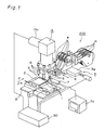
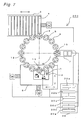
- Fig. 1 is a perspective view illustrating an overall configuration of a component mounting apparatus 200 in accordance with the first embodiment of the present invention
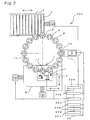
- Fig. 2 shows connection of a control device 30 in the component mounting apparatus 200.
- the component mounting apparatus 200 is a rotary type component mounting apparatus having sixteen nozzle units 6 that are provided with the suction nozzles 5 and that are arranged at uniform intervals along an annular path 12.
- the component mounting apparatus 200 has a component conveying device 13, a component feeding device 3, a component recognizing device 7, and an XY-table 8.
- the component conveying device 13, the component feeding device 3, the component recognizing device 7, and the XY-table 8 are connected respectively to the control device 30.
- the component conveying device 13 has the nozzle units 6 and is operated under control of the control device 30 so as to cause the nozzle units 6 to make a unidirectional intermittent rotational motion clockwise along the path 12 shown in Fig. 2 .
- the suction nozzle 5 can be turned about the central axis 5b shown in Fig. 11 and the turning is controlled by the control device 30.
- the component feeding device 3 is provided under the nozzle units 6 as shown in Fig. 1 at a component sucking position 9 on the path 12 shown in Fig. 2 .
- the component recognizing device 7 is provided under the nozzle units 6 as shown in Fig. 1 at a component recognizing position 10 on the path 12 shifted clockwise by 90° along the path 12 from the component sucking position 9 shown in Fig. 2 .
- the XY-table 8 is provided under the nozzle units 6 as shown in Fig. 1 at a component placing position 11 on the path 12 shifted clockwise by 90° on the path 12 from the component recognizing position 10 shown in Fig. 2 .
- the nozzle units 6 stop at the component sucking position 9, the component recognizing position 10, and the component placing position 11 shown in Fig. 2 , in the unidirectional intermittent rotational motion caused by the component conveying device 13.
- the component feeding device 3 feeds components 1 that are to be sucked by the suction nozzles 5 positioned at the component sucking position 9, and has a component feeding table 3a capable of reciprocating in directions of X-axis in Fig. 1 under control of the control device 30 and has a plurality of parts cassettes 4 attached onto the component feeding table 3a. Types, shapes, outside dimensions, and the like of the components 1 contained in tapes wound in reels 14 attached to the parts cassettes 4 are different from each other in every parts cassette 4. Thus selection of the components 1 by the component feeding device 3 is achieved to make the parts cassette 4 that feeds the component 1 to be sucked face a lower end 5a of the suction nozzle 5 provided on the nozzle unit 6 positioned in the component feeding position 9 shown in Fig. 11 by actuating the component feeding table 3a with the control device 30.
- the component recognizing device 7 recognizes positions and status of the suction of the components 1, which have been conveyed to the component recognizing position 10, at the suction nozzles 5.
- the component recognition information of the positions and status of the suction of the components 1 recognized by the component recognizing device 7 is outputted from the component recognizing device 7 to the control device 30 for calculation of the correction quantities in the placement of the components 1.
- a monitor 7a is connected to the component recognizing device 7.
- the monitor 7a can display the positions and status of the suction of the components 1 in the predetermined space recognized by the component recognizing device 7 as shown in Fig. 3 .
- 11 is at least one of variation in position in which the component 1 is contained in a cavity of the tape, variation in position of installation of the parts cassette 4 in the component feeding device 3, variation of the parts cassette 4 itself, variation in status of attachment of the suction nozzle 5 in the component mounting apparatus 200, variation in feeding position of the tape in the parts cassette 4, and the like.
- the XY-table 8 holds the resin board 2 as an example of the circuit-formed member on which the components 1 are to be placed, and is capable of moving the resin board 2 freely in directions of X-axis and of Y-axis in Fig. 1 under control of the control device 30. With the movement of the resin board 2 by the XY-table 8, a placing position (not shown) on the resin board 2 on which the component 1 conveyed to the component placing position 11 is to be placed can be placed under the component placing position 11.
- control unit 30 has an NC data storage section 30a, a correction quantity calculating section 30b, a correction quantity storage section 30c, a nozzle central axis storage section 30d, a deviation calculating section 30e, and a threshold value storage section 30f.
- the NC data storage section 30a stores a NC data registering an order in which the components 1 are fed from the component feeding device 3, a setting velocity set for conveyance of the components 1 from the component feeding position 9 to the component placing position 11, and coordinates on the resin board 2 for the placement of the components 1 and the like.
- the correction quantity calculating section 30b calculates a correction quantity for the placement of the component 1 on the resin board 2 on basis of the NC data read from the NC data storage section 30a, and position data of the center of gravity 1a of the component 1 shown in Fig. 11 and angle data of an inclination ⁇ of the component 1 that are obtained on basis of the component recognition information inputted from the component recognizing device 7.
- In the correction quantity storage section 30c is temporarily stored the correction quantity calculated by the correction quantity calculating section 30b.
- the control device 30 is capable of positioning of the resin board 2 with actuation of the XY-table 8 based on the NC data and the correction quantity from the correction quantity storage section 30c.
- the control device 30 is also capable of correcting the angle of the component 1 with turning of the suction nozzle 5 about the central axis 5a in Fig. 11 based on the correction quantity read from the correction quantity storage section 30c.
- the position data of the central axis 5b of the suction nozzle 5 is obtained by recognizing the suction nozzle 5' that has not sucked the component 1 by the component recognizing device 7 shown in Fig. 2 .
- the deviation calculating section 30e calculates the deviation ⁇ L shown in Fig. 11 , and the deviation ⁇ L is calculated on basis of the position data of the central axis 5b read from the nozzle central axis storage section 30d shown in Fig. 2 and the position data of the center of gravity 1a of the component 1 based on the component recognition information.
- the control device 30 shown in Fig. 2 compares the threshold value read from the threshold value storage section 30f with the deviation ⁇ L. If the deviation ⁇ L is larger than the threshold value as a result of the comparison, the control device 30 determines a velocity of conveyance of the component 1 following the recognition of the component and preceding the placement of the component by decreasing the setting velocity set initially, and controls operation of the component conveying device 13 shown in Fig. 1 on basis of the determined velocity of conveyance. Thus the component conveying device 13 conveys the component 1 at the velocity of conveyance, from the component recognizing position 10 to the component placing position 11.
- the control device 30 determines the setting velocity as the velocity of conveyance following the recognition of the component and preceding the placement of the component, and controls operation of the component conveying device 13 shown in Fig. 1 on basis of the setting velocity, so that the component conveying device 13 conveys the component 1 at the setting velocity from the component recognizing position 10 to the component placing position 11.
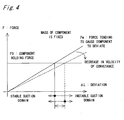
- Fig. 4 shows a graph representing a relation between a force Fm that is caused in the component 1 by the conveyance of the component 1 and that tends to cause the component 1 to deviate from the sucking position of the component 1 recognized by the component recognizing device 7 and a component holding force F0 the suction nozzle 5 has.
- a horizontal axis represents the deviation ⁇ L and a vertical axis represents a force F that acts on the component 1.
- the component holding force F0 is uniquely determined by a vacuum pressure, an aperture diameter, and the like at the lower end 5a shown in Fig. 11 of the suction nozzle 5. As shown in Fig.
- the component holding force F0 therefore has a fixed value on condition that a type of the suction nozzle 5 for use is fixed.
- the force Fm that tends to cause the component 1 to deviate is exerted from outside of the component 1 owing to an acceleration of the velocity of conveyance and the like in a period of time following the recognition of the component and preceding the placement of the component, and the force Fm increases proportionally with the velocity of conveyance.
- the center of gravity 1a of the component 1 deviates from the central axis 5b of the suction nozzle 5 with the larger deviation ⁇ L.
- the threshold value is a deviation based on the force Fm that tends to cause the component 1 to deviate and that is balanced with the component holding force F0 on condition that the velocity of conveyance is set at the setting velocity. If the deviation ⁇ L exceeds the threshold value in the component mounting apparatus 200 shown in Fig.
- the force Fm tending to cause the component 1 to deviate exceeds the component holding force F0 on condition that the velocity of conveyance is set at the setting velocity and thereby causing instable suction by the suction nozzle 5 and further deviation of the component 1 after the recognition of the component.
- the control device 30 decides to obtain the velocity of conveyance for the period of time following the recognition of the component and preceding the placement of the component by decreasing the setting velocity.
- the following operations are performed for the determination of the velocity of conveyance according to the decision. That is, the control device 30 initially calculates the force Fm tending to cause the component 1 to deviate on condition that the velocity of conveyance is set at the setting velocity, on basis of the deviation ⁇ L. The control device 30 subsequently compares the force Fm tending to cause the component 1 to deviate of the result of the calculation, with the component holding force F0 which has been set previously.
- This comparing operation is an operation for finding a difference between the force Fm tending to cause the component 1 which force exceeds the component holding force F0 and the component holding force F0 because the threshold value is a value corresponding to a state in which the force Fm tending to cause the component 1 to deviate is balanced with the component holding force F0 as described above. Subsequently, a quantity by which the setting velocity is to be decreased is determined on basis of the result of the comparison, and the velocity of conveyance is thereby determined.
- the quantity by which the setting velocity is to be decreased is increased with increase in the difference between the deviation ⁇ L and the threshold value when the deviation ⁇ L is larger than the threshold value, because the force Fm tending to cause the component 1 to deviate increases proportionally with the velocity of conveyance and because the force Fm tending to cause the component 1 to deviate is approximately proportional to the deviation ⁇ L.
- the quantity to be decreased from the setting velocity is obtained by the result of the comparison, and then the velocity of conveyance is determined by subtracting the quantity to be decreased from the setting velocity.
- the force Fm tending to cause the component 1 to deviate can be restricted by conveyance of the component 1 at the determined velocity of conveyance.
- the quantity to be decreased is changed proportionally with the difference between the deviation ⁇ L and the threshold value when the deviation ⁇ L is larger than the threshold value; in a first modification of the embodiment, however, the quantity to be decreased may previously be set at a fixed value and the velocity of conveyance may be determined by subtraction of the fixed value from the setting velocity when the deviation ⁇ L is larger than the threshold value.
- the fixed value is a value that is subtracted from the setting velocity and that, for example, can obtain the velocity of conveyance preventing a further change in the deviation ⁇ L in the conveyance of any component 1 from the setting velocity.
- the fixed value is one value regardless of magnitudes of the difference between the deviation ⁇ L and the threshold value.
- the method of controlling the velocity of conveyance for the period of time following the recognition of the component and preceding the placement of the component is not limited to the method in which the velocity of conveyance is controlled by the decrease from the setting velocity set initially when the deviation ⁇ L is larger than the threshold value.
- corresponding velocities according to magnitudes of the deviation ⁇ L may previously be set as one item of the NC data, a corresponding velocity corresponding to the deviation ⁇ L may be introduced on basis of a magnitude of the deviation ⁇ L of the component 1 recognized by the component recognizing device 7 in the recognition of the component, and the corresponding velocity may be used as the velocity of conveyance for the period of time following the recognition of the component and preceding the placement of the component.
- each corresponding velocity is equivalent to a proper velocity of conveyance.
- the corresponding velocity is a velocity that prevents a further change in the deviation ⁇ L of the component 1 in the conveyance following the recognition of the component and preceding the placement of the component.
- the velocity of conveyance can be controlled more precisely than in the first modification because the corresponding velocities are set according to individual magnitudes of the deviation ⁇ L.
- the second modification is the method of determining the velocity of conveyance without use of the setting velocity as described above and is not the method in which the velocity of conveyance is determined by the subtraction as in the embodiment described above.
- the velocity of conveyance can be determined more precisely than in the second modification because the operation of the comparison on basis of the deviation ⁇ L is performed and the velocity of conveyance is thus calculated each time the component is recognized by the component recognizing device 7.
- the control device 30 controls the operation of the component conveying device 13.
- the component conveying device 13 moves the nozzle unit 6 along the path 12 at the determined velocity of conveyance. With the movement of the nozzle unit 6, the component 1 is conveyed from the component recognizing position 10 to the component placing position 11 at the velocity of conveyance determined by the decrease from the setting velocity.
- the control device 30 When the control device 30 performs the control for decreasing the setting velocity and setting the decreased velocity as the velocity of conveyance, the force Fm tending to cause the component 1 to deviate is decreased for the component holding force F0 as shown in Fig. 4 , so that the suction of the component 1 by the suction nozzle 5 shown in Fig. 1 is stabilized.
- the stabilization of the suction of the component 1 by the suction nozzle 5 prevents the deviation ⁇ L of the component 1 from changing when the component 1 is conveyed after the recognition of the component.
- position correction in the positioning of the resin board 2 can be achieved only by the correction quantity and the component 1 can be placed accurately on the resin board 2.
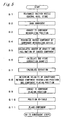
- FIG. 5 is a flowchart illustrating a series of mounting operations in the component mounting apparatus 200.
- a step (designated as "S" in the drawing) 1 initially, the component conveying device 13 is actuated in status in which all the suction nozzles 5 shown in Fig. 1 are free of suction of the components 1, and then positions of the central axes 5b shown in Fig. 11 of all the suction nozzles 5 are recognized by the component recognizing device 7.
- the positions of the central axes 5b shown in Fig. 11 which positions have been recognized by the component recognizing device 7 shown in Fig. 1 are stored as data in the nozzle central axis storage section 30d of the control device 30 shown in Fig. 2 .
- the component 1 is sucked by the suction nozzle 5 at the component sucking position 9 shown in Fig. 2 .
- the control device 30 actuates the component feeding table 3a on basis of the NC data read from the NC data storage section 30a, and the parts cassette 4 capable of feeding the component 1 specified in the NC data is positioned under the nozzle unit 6 positioned at the component sucking position 9.
- the component 1 is then sucked from the parts cassette 4 by the suction nozzle 5 provided on the nozzle unit 6.
- the suction nozzle 5 sucks the component 1 with a fixed component holding force for the period of time following the suction of the component and preceding the placement of the component.
- the component 1 is conveyed to the component recognizing position 10 with the movement of the nozzle unit 6 shown in Fig. 2 .
- the component 1 is recognized by the component recognizing device 7 shown in Fig. 1 .
- the control device 30 shown in Fig. 1 calculates the position of the center of gravity 1a of the component 1 shown in Fig. 11 and an inclination ⁇ of the component 1 on basis of component recognition information obtained from the recognition.
- the control device 30 shown in Fig. 2 then calculates the correction quantity on basis of the position data of the center of gravity 1a and angle data of the inclination ⁇ of the component 1, and stores the correction quantity in the correction quantity storage section 30c shown in Fig. 2 .
- the correction quantity is thus calculated and, as shown in a step 7 shown in Fig. 5 , the control device 30 shown in Fig. 2 then calculates the deviation ⁇ L on basis of the position data of the central axis 5b of the suction nozzle 5 shown in Fig. 11 which data has been read from the nozzle central axis storage section 30d and the position data of the center of gravity 1a shown in Fig. 11 of the component 1 which data has been calculated in the step 5 shown in Fig. 5 .
- the control device 30 shown in Fig. 2 compares the threshold value read from the threshold value storage section 30f with the deviation ⁇ L, and on basis of the result of the comparison, decides to control the velocity of conveyance of the component 1 for the period of time following the recognition of the component and preceding the placement of the component so as to decrease or maintain the setting velocity. If the deviation ⁇ L exceeds the threshold value and the control device 30 decides to decrease the velocity of conveyance in comparison with the setting velocity, the control device 30 calculates the force Fm tending to cause the component 1 to deviate on condition that the velocity of conveyance is set at the setting velocity, on basis of the magnitude of the deviation ⁇ L.
- the control device 30 subsequently compares the component holding force F0 of the suction nozzle 5 with the force Fm tending to cause the component 1 to deviate, thereby obtaining a difference between the force Fm tending to cause the component 1 and the component holding force F0. Then the control device 30 obtains the quantity by which the setting velocity is to be decreased on basis of the difference between the force Fm tending to cause the component 1 and the component holding force F0, thereby determining the velocity of conveyance of the component 1 for the period of time following the recognition of the component and preceding the placement of the component.
- the control device 30 After determining the velocity of conveyance, the control device 30 actuates the component conveying device 13 shown in Fig. 1 so that the velocity of conveyance of component conveying device 13 has the value determined in the step 8 shown in Fig. 5 , and the control device 30 moves the nozzle unit 6 at the velocity of conveyance from the component recognizing position 10 along the path 12 shown in Fig. 2 . With the movement of the nozzle unit 6, as shown in a step 9 shown in Fig. 5 , the component 1 is conveyed to the component placing position 11 shown in Fig. 2 . Between the recognition of the component and the placement of the component, the control device 30 causes the suction nozzle 5 to turn about the central axis 5a shown in Fig. 11 on basis of the correction quantity read from the correction quantity storage section 30c, and thus corrects the angle of the component 1.
- the control device 30 shown in Fig. 2 performs positioning of the resin board 2 held on the XY-table 8 on basis of the NC data from the NC data storage section 30a and the correction quantity from the correction quantity storage section 30c.
- the component 1 When the component 1 is disposed at the component placing position 11 after completion of the positioning of the resin board 2 and the correction of the angle of the component 1, the component 1 is placed on a placing position on the resin board 2 shown in Fig. 1 which position has been registered in the NC data, as shown in a step 11 shown in Fig. 5 .
- the nozzle unit 6 having the suction nozzles 5 is moved by the component conveying device 13 along the path 12 shown in Fig. 2 to the component sucking position 9, and the series of operations from the step 2 to the step 11 shown in Fig. 5 are repeated again.
- the component mounting apparatus 200 determines the deviation ⁇ L on basis of the component recognition information on the component 1 obtained by the component recognizing device 7, and determines the velocity of conveyance of the component 1 for the period of time following the recognition of the component and preceding the placement of the component, on basis of the magnitude of the deviation ⁇ L.
- the conveyance of the component 1 at the determined velocity of conveyance prevents the component 1 from further deviating from the status in the recognition of the component, in the period of time following the recognition of the component and preceding the placement of the component.
- the position at which the component 1 is actually placed on the resin board 2 is prevented from deviating from the placing position on the resin board 2 which position is introduced from the NC data and the correction quantity based on the component recognition information, when the component 1 is placed on the resin board 2.
- the component 1 can be placed on the placing position at all times, and consequently the component mounting apparatus 200 can improve the accuracy and rate of the placement of the component 1 on the resin board 2.
- the control restricts instability in the suction that is caused by excess of the force Fm tending to cause the component 1 to deviate over the component holding force F0.
- the determination of the force Fm tending to cause the component 1 to deviate can be omitted when the force Fm tending to cause the component 1 to deviate is not larger than the component holding force F0.
- control device 30 is capable of reading the data of the setting velocities and thereby controlling the velocity of conveyance of the component 1 for the period of time following the recognition of the component and preceding the placement of the component.
- the velocity of conveyance of the component 1 for the period of time following the recognition of the component and preceding the placement of the component is controlled on basis of a fact that the magnitudes of the force tending to cause the component 1 to deviate are approximately proportional to the magnitudes of the deviation ⁇ L shown in Fig. 11 .
- a control device 30 in a component mounting apparatus 300 in accordance with a second embodiment may have a component information storage section 30g in which information on properties such as masses, volumes, and heights of the components 1 is previously registered, so as to be capable of addressing variation in the masses of the components 1.
- the control device 30 is capable of finding the force Fm tending to cause the component 1 to deviate on basis of the deviation ⁇ L found by the component recognition information on the component 1 obtained from the component recognizing device 7 and on basis of the information on the properties of the component 1 read from the component information storage section 30g.
- the control device 30 is capable of controlling the velocity of conveyance for the period of time following the recognition of the component and preceding the placement of the component, on basis of a result of the comparison between the force Fm tending to cause the component 1 to deviate and the component holding force F0.
- the velocity of conveyance of the component 1 for the period of time following the recognition of the component and preceding the placement of the component can be controlled further precisely according to the force Fm tending to cause the component 1 to deviate that varies with the properties of the component 1.
- the mass of the component 1 can be calculated by previous registration of a volume of the component 1 as a property of the component 1 in the component information storage section 30g and by registration of a density of the component 1, or a tentative mass of the component 1 can be calculated by registration of commonly assumed specific gravities of iron and the like as an example in the component information storage section 30g.
- the velocity of conveyance can be determined on basis of the mass.
- an outside diameter of the component 1 is often registered previously in a component library data for the recognition of the component 1, and therefore calculation of the mass of the component 1 with use of the component library data is more convenient than that with further registration of the mass of the component 1 in the component information storage section 30g.
- the first embodiment and the second embodiment have been described as those in which the suction nozzles 5 have a fixed component holding force.
- shapes and aperture diameters of the lower ends 5a shown in Fig. 11 of the suction nozzles 5 vary with the types of the suction nozzles 5.
- Suction areas on the components 1 sucked by the suction nozzles 5 vary with the shapes and aperture diameters of the lower ends 5a, and thus the component holding forces F0 that the suction nozzles 5 have increase and decrease with variation in the suction area. As shown in Fig.
- a stable suction domain of the deviation ⁇ L with respect to the component holding force F0 also increases and decreases with the increase and decrease in the component holding force F0. Consequently, it is necessary to control the velocity of conveyance of the component 1 in accordance with the variation in the component holding force.
- a control device 30 may have a storage section 30h for suction nozzle in which information representing a relation between types of the suction nozzles 5 and the component holding forces is stored.
- the control device 30 determines the force Fm tending to cause the component 1 to deviate shown in Fig. 8 on basis of the deviation ⁇ L shown in Fig.
- the velocity of conveyance after the recognition of the component can be controlled even though magnitudes of the component holding force F0 vary with types of the suction nozzles 5 that suck the components 1, so that the accuracy and rate of placement of the components 1 on the resin board 2 can be improved.
- the component holding force F0 is uniquely determined by the type of the suction nozzle 5, and therefore more convenient setting is achieved than that with the registration of the properties for each component 1 as in the second embodiment.
- the nozzle unit 6 provided in the component mounting apparatus 400 is a multi-nozzle unit having a plurality of suction nozzles 5 of different types which can be selected, a registration number is assigned to each suction nozzle 5 of the nozzle unit 6 and the registration numbers of the suction nozzles 5 are often registered previously in the component library data. Therefore, according to calculation of the component holding force of the suction nozzle 5 by introducing the type of the suction nozzle 5, it is more convenient in comparison with further registration of the component holding force F0 of the suction nozzle 5 in the storage section 30h for suction nozzle.
- the component mounting methods in accordance with the first through third embodiments can be used in a component mounting apparatus of a XY-robot type in which a nozzle unit 6 having the suction nozzles 5 is capable of moving freely on an XY-plane, and can restrict a change in the deviation ⁇ L after the recognition of the component.
Description
- The present invention relates to a component mounting apparatus and a component mounting method for mounting components stably on a circuit-formed member such as resin boards or the like, and particularly relates to a component mounting apparatus and a component mounting method in which the components are sucked by suction nozzles to be held and conveyed.
- In a component mounting apparatus for mounting components on a circuit-formed member such as resin boards or the like, it is important to recognize a component and to determine a correction quantity with respect to a placing position on the circuit-formed member for placement of the component on the circuit-formed member on basis of a result of the recognition before the placement of the component on the circuit-formed member, in order to improve an accuracy of placement and a rate of placement in the placement of the components.
The documentEP-A-1220 595 for example, discloses a component mounting apparatus. -
Fig. 10 shows a conventionalcomponent mounting apparatus 100 formounting components 1 on aresin board 2 as an example of the circuit-formed member. Theresin board 2 is a printed board on which a circuit pattern has been formed for mounting of thecomponents 1 that are electronic-components, and theresin board 2 is held on an XY-table 8.Parts cassettes 4 provided in acomponent feeding device 3 contain thecomponents 1 by taping, and thecomponents 1 are sucked one by one at acomponent sucking position 9 from theparts cassettes 4 bysuction nozzles 5 provided on anozzle unit 6 that is making a unidirectional intermittent rotational motion clockwise inFig. 10 along anannular path 12. - After the suction operation at the
component sucking position 9, thenozzle unit 6 moves along thepath 12 to acomponent recognizing position 10, and suction status of thecomponents 1 sucked on thesuction nozzles 5 of thenozzle unit 6 are recognized in a predetermined space by acomponent recognizing device 7. Acontrol device 20 into which information obtained from thecomponent recognizing device 7 on the recognition of thecomponents 1 have been inputted calculates correction quantities for the placement on basis of the component recognition information and stores the correction quantities in a correction quantity storage section 20c. After the recognition of thecomponents 1, thenozzle unit 6 moves along thepath 12 to a component placingposition 11. - The
control device 20 then calculates coordinates of the placing position on theresin board 2 on basis of coordinates on theresin board 2 registered in NC data read from an NC data storage section 20a and on basis of the correction quantity stored in the correction quantity storage section 20c, and calculates a turning angle of thesuction nozzle 5 for angle correction on basis of the correction quantity. Thecontrol device 20 turns thesuction nozzle 5 about a central axis thereof on basis of the calculated turning angle, and actuates the XY-table 8 to move theresin board 2 on basis of the calculated coordinates of the placing position on theresin board 2. When thenozzle unit 6 is positioned at the component placingposition 11, thecomponents 1 sucked by thesuction nozzles 5 of thenozzle unit 6 are placed on theresin board 2. -
Fig. 11 shows a deviation ΔL and an inclination Δθ relative to a normal suction status 1b of acomponent 1 sucked by asuction nozzle 5. The normal suction status 1b of thecomponent 1 refers to status in which a center of gravity 1a of thecomponent 1 coincides with a central axis 5b of thesuction nozzle 5 as shown by broken lines inFig. 11 . In thecomponent mounting apparatus 100, as described above, thecomponents 1 are held with suction by thesuction nozzles 5 and are placed on theresin board 2. In the suction operation shown inFig. 10 at thecomponent sucking position 9, a deviation of acomponent 1 by the deviation ΔL may be caused as shown infig. 11 by a positional variation of thecomponents 1 in cavities of the tape provided in theparts cassettes 4, a variation in status of attachment of thesuction nozzles 5 in thecomponent mounting apparatus 100, or the like. - Even if the center of gravity 1a of a
component 1 misses the central axis 5b of thesuction nozzle 5 when thecomponent 1 is sucked by thesuction nozzle 5, thecomponent 1 is conveyed at a conveyance velocity that has been set originally, by anozzle unit 6 that travels along thepath 12 shown inFig. 10 . Accordingly, a moment acting on thecomponent 1 increases with the deviation ΔL shown inFig. 11 because an inertial force is exerted on thecomponent 1 in accordance with an acceleration in the travel of thenozzle unit 6. As a result, while thenozzle unit 6 travels after thecomponent recognizing device 7 recognizes thecomponents 1 to calculate the correction quantities until thecomponents 1 are placed at the component placingposition 11, moment forces tending to cause thecomponents 1 to deviate from the central axes 5b of thesuction nozzles 5 act on thecomponents 1, so that thecomponents 1 on lower ends 5a of thesuction nozzles 5 may further deviate from the status in the recognition of the components. In the conventionalcomponent mounting apparatus 100, therefore, there is a possibility that a position of acomponent 1 placed on theresin board 2 may deviate from the placing position on theresin board 2 based on the NC data and the component recognition information on condition that thecomponent 1 is placed on theresin board 2 only with the position correction based on the correction quantity. - Though the above conventional art has been described with reference to the
component mounting apparatus 100 of rotary type, a change in the deviation caused after the recognition of components cannot be corrected even in a component mounting apparatus of XY-robot type in whichnozzle units 6 havingsuction nozzles 5 can be moved freely on an XY-plane. - The present invention has been made for solving the problems described above and an object of the present invention is to provide a component mounting apparatus and a component mounting method that improve an accuracy and a rate of placement of components on a circuit-formed member.
- For achievement of the above object, the invention is configured as follows.
- According to the first aspect of the present invention, there is provided a component mounting apparatus as defined in
claim 1. - The above first aspect may be designed so that the control of the velocity of conveyance performed by the control device is a control by which a setting velocity set initially is decreased or retained for a determination of the velocity of conveyance.
- The above first aspect may be designed so that the control device determines a force which is caused in the component by the conveyance of the component at the setting velocity after the recognition of the component and tends to cause the component to deviate from a suction position of the component on the suction nozzle in the recognition of the component, on basis of the deviation, and controls the velocity of conveyance on basis of a result of comparison between the force tending to cause the component to deviate and a component holding force which the suction nozzle has.
- The above first aspect may be designed so that the control device decreases the setting velocity to determine the velocity of conveyance when the deviation found on basis of the component recognition information is larger than a threshold value which is a magnitude of deviation based on the force tending to cause the component to deviate balanced with the component holding force.
- The above first aspect may be designed so that the control device comprises a component information storage section in which information on properties of the component held by the suction nozzle is stored, and controls the velocity of conveyance on basis of a result of comparison between the component holding force and the force tending to cause the component to deviate which is read from the component data storage section and varies with the properties of the component.
- The above first aspect may be designed so that the component conveying device comprises a plurality of suction nozzles of different types, and
wherein the control device comprises a storage section for suction nozzle in which information representing a relation between types of the suction nozzles and the component holding forces is stored, and controls the velocity of conveyance on basis of a result of comparison between the component holding force of the suction nozzle sucking the component recognized by the component recognizing device, the force being read from the storage section for suction nozzle, and the force tending to cause the component to deviate which acts on the component sucked by the suction nozzle. - In a second aspect of the present invention, there is provided a component mounting method according to
claim 8. - The above second aspect may be designed so that the control of the velocity of conveyance is a control by which a setting velocity set initially is decreased or retained for the determination of the velocity of conveyance.
- The above second aspect may be designed so that the control of the velocity of conveyance based on the deviation is a control in which a force caused in the component by the conveyance at the setting velocity after the recognition of the component and tending to cause the component to deviate from a suction position of the component on the suction nozzle in the recognition of the component is determined on basis of the deviation, and in which the velocity of conveyance is controlled on basis of a result of comparison between the force tending to cause the component to deviate and a component holding force which the suction nozzle has.
- The above second aspect may be designed so that the control of the velocity of conveyance based on the deviation is a control in which the setting velocity is decreased for the determination of the velocity of conveyance when the deviation found on basis of the component recognition information is larger than a threshold value which is a deviation based on the force tending to cause the component to deviate balanced with the component holding force.
- The above second aspect may be designed so that the control of the velocity of conveyance based on the deviation is a control in consideration of the force tending to cause the component to deviate which varies with properties of the component.
- The above second aspect may be designed so that the control of the velocity of conveyance based on the deviation is a control in consideration of the component holding force which varies with types of the suction nozzles sucking the component.
- In the component mounting apparatus of the first aspect of the invention and the component mounting method of the second aspect of the invention that have been described above, the component sucked by the suction nozzle that travels along the path from the component sucking position to the component placing position is recognized at the component recognizing position on the path, the deviation is determined on basis of the component recognition information obtained from the recognition of the component, and the velocity of conveyance for the period of time following the recognition of the component and preceding the placement of the component is thereby controlled on basis of the obtained magnitude of the deviation. As a result, the conveyance of the component at the determined velocity of conveyance for the period of time following the recognition of the component and preceding the placement of the component can restrict a further change in the deviation after the recognition of the component and can improve the accuracy and rate of placement of the component on the circuit-formed member.
- The employment of a configuration in which the setting velocity set initially is decreased or retained for the determination of the velocity of conveyance may obviate the necessity of experiment or the like for the determination of the velocity of conveyance and may make it possible to determine the velocity of conveyance more precisely in comparison with, for example, the method in which velocities of conveyance corresponding to deviations are previously determined or the like that is conceivable as one of methods of determining the velocity of conveyance from the.deviation.
- By a configuration in which the force acting on the component with the conveyance of the component at the setting velocity after the recognition of the component and tending to cause the component to deviate from the suction position of the component on the suction nozzle in the recognition of the component is determined on basis of the deviation, the velocity of conveyance can be determined on basis of the result of the comparison between the force tending to cause the component to deviate and the component holding force that the suction nozzle has. Thus instability in the suction that is caused by excess of the force tending to cause the component to deviate over the component holding force with increase in the deviation can be restricted, and further change in the deviation after the recognition of the component can be restricted.
- In a configuration, the deviation of the component on condition that the component holding force is balanced with the force tending to cause the component to deviate may be set as the threshold value, and the velocity of conveyance may be determined by decreasing the setting velocity when a deviation of the component from the normal suction status is larger than the threshold value. The configuration allows omission of the determination of the force tending to cause the component to deviate when the deviation is not larger than the threshold value.
- By the control of the velocity of conveyance on basis of the result of the comparison between the component holding force and the force tending to cause the component to deviate that varies with the properties of the component, the velocity of conveyance can be controlled precisely so as to correspond to the variation in the force tending to cause the component to deviate according to the variation in the properties of the component. Thus the accuracy and rate of placement can be improved even on condition that a plurality of components having different masses, volumes, and heights are placed on the circuit-formed member.
- In the configuration which has a plurality of suction nozzles of different types and in which magnitudes of the component holding force vary with the types of the suction nozzles, the velocity of conveyance can be controlled on basis of the result of the comparison between the component holding force that varies with the types of the suction nozzles and the force tending to cause the component to deviate. Thus the accuracy and rate of placement of the components on the circuit-formed member can be improved.
- These and other objects and features of the invention will be apparent from the following description concerning preferred embodiments with reference to the accompanying drawings, in which:
-
Fig. 1 is a perspective view of a component mounting apparatus in accordance with a first embodiment of the present invention; -
Fig. 2 is an explanatory view illustrating connection of a control device in the component mounting apparatus shown inFig. 1 ; -
Fig. 3 is a perspective view illustrating recognition of a component by a component recognizing device provided in the component mounting apparatus shown inFig. 1 ; -
Fig. 4 is a graph representing a relation between forces tending to cause a component to deviate with respect to a predetermined component holding force and deviations of the component; -
Fig. 5 is a flowchart illustrating a component mounting method in accordance with the first embodiment of the present invention; -
Fig. 6 is a graph representing a relation between forces tending to cause a component to deviate with respect to a predetermined component holding force and masses of the component; -
Fig. 7 is an explanatory view illustrating connection of a control device in a component mounting apparatus in accordance with a second embodiment of the present invention; -
Fig. 8 is a graph representing a relation between component holding forces that a suction nozzle has and forces tending to cause a component to deviate; -
Fig. 9 is an explanatory view illustrating connection of a control device in a component mounting apparatus in accordance with a third embodiment of the present invention; -
Fig. 10 is an explanatory view illustrating connection of a control device in a conventional component mounting apparatus; and -
Fig. 11 is an explanatory view illustrating a deviation from a normal suction status and an inclination of a component. - Hereinbelow, a component mounting apparatus and a component mounting method that are a first embodiment of the present invention will be described in detail with reference to the drawings.
- In the component mounting apparatus and the component' mounting method, components such as electronic components, machine parts, optical components or the like are mounted on a circuit-formed member such as circuit boards including resin boards, paper-phenol boards, ceramic boards, glass-epoxy boards, film substrates or the like, circuit boards including single-layer boards and multilayer boards, components, enclosures, and frames. In the drawings, the same members are designated by the same reference characters. In the component mounting apparatus and the component mounting method, the components are held with suction by suction nozzles and, as shown by broken lines in
Fig. 11 , status 1b in which a center of gravity 1a of acomponent 1 coincides with a central axis 5b of asuction nozzle 5 is defined as a normal suction status of thecomponent 1. -
Fig. 1 is a perspective view illustrating an overall configuration of acomponent mounting apparatus 200 in accordance with the first embodiment of the present invention, andFig. 2 shows connection of acontrol device 30 in thecomponent mounting apparatus 200. - As shown in
Fig. 2 , thecomponent mounting apparatus 200 is a rotary type component mounting apparatus having sixteennozzle units 6 that are provided with thesuction nozzles 5 and that are arranged at uniform intervals along anannular path 12. As shown in.Fig. 1 , thecomponent mounting apparatus 200 has acomponent conveying device 13, acomponent feeding device 3, acomponent recognizing device 7, and an XY-table 8. Thecomponent conveying device 13, thecomponent feeding device 3, thecomponent recognizing device 7, and the XY-table 8 are connected respectively to thecontrol device 30. - The
component conveying device 13 has thenozzle units 6 and is operated under control of thecontrol device 30 so as to cause thenozzle units 6 to make a unidirectional intermittent rotational motion clockwise along thepath 12 shown inFig. 2 . Thuscomponents 1 sucked by thesuction nozzles 5 are conveyed with the unidirectional intermittent rotational motion of thenozzle units 6. An angle of rotation in the unidirectional intermittent rotational motion is 22.5°. Thesuction nozzle 5 can be turned about the central axis 5b shown inFig. 11 and the turning is controlled by thecontrol device 30. - The
component feeding device 3 is provided under thenozzle units 6 as shown inFig. 1 at acomponent sucking position 9 on thepath 12 shown inFig. 2 . Thecomponent recognizing device 7 is provided under thenozzle units 6 as shown inFig. 1 at acomponent recognizing position 10 on thepath 12 shifted clockwise by 90° along thepath 12 from thecomponent sucking position 9 shown inFig. 2 . The XY-table 8 is provided under thenozzle units 6 as shown inFig. 1 at acomponent placing position 11 on thepath 12 shifted clockwise by 90° on thepath 12 from thecomponent recognizing position 10 shown inFig. 2 . Thenozzle units 6 stop at thecomponent sucking position 9, thecomponent recognizing position 10, and thecomponent placing position 11 shown inFig. 2 , in the unidirectional intermittent rotational motion caused by thecomponent conveying device 13. - The
component feeding device 3 feedscomponents 1 that are to be sucked by thesuction nozzles 5 positioned at thecomponent sucking position 9, and has a component feeding table 3a capable of reciprocating in directions of X-axis inFig. 1 under control of thecontrol device 30 and has a plurality ofparts cassettes 4 attached onto the component feeding table 3a. Types, shapes, outside dimensions, and the like of thecomponents 1 contained in tapes wound inreels 14 attached to theparts cassettes 4 are different from each other in everyparts cassette 4. Thus selection of thecomponents 1 by thecomponent feeding device 3 is achieved to make theparts cassette 4 that feeds thecomponent 1 to be sucked face a lower end 5a of thesuction nozzle 5 provided on thenozzle unit 6 positioned in thecomponent feeding position 9 shown inFig. 11 by actuating the component feeding table 3a with thecontrol device 30. - The
component recognizing device 7 recognizes positions and status of the suction of thecomponents 1, which have been conveyed to thecomponent recognizing position 10, at thesuction nozzles 5. The component recognition information of the positions and status of the suction of thecomponents 1 recognized by thecomponent recognizing device 7 is outputted from thecomponent recognizing device 7 to thecontrol device 30 for calculation of the correction quantities in the placement of thecomponents 1. As shown inFig. 1 , a monitor 7a is connected to thecomponent recognizing device 7. Thus the monitor 7a can display the positions and status of the suction of thecomponents 1 in the predetermined space recognized by thecomponent recognizing device 7 as shown inFig. 3 . A specific factor by which thecomponents 1 recognized by thecomponent recognizing device 7 deviate from the normal suction status 1b shown inFig. 11 is at least one of variation in position in which thecomponent 1 is contained in a cavity of the tape, variation in position of installation of theparts cassette 4 in thecomponent feeding device 3, variation of theparts cassette 4 itself, variation in status of attachment of thesuction nozzle 5 in thecomponent mounting apparatus 200, variation in feeding position of the tape in theparts cassette 4, and the like. - The XY-table 8 holds the
resin board 2 as an example of the circuit-formed member on which thecomponents 1 are to be placed, and is capable of moving theresin board 2 freely in directions of X-axis and of Y-axis inFig. 1 under control of thecontrol device 30. With the movement of theresin board 2 by the XY-table 8, a placing position (not shown) on theresin board 2 on which thecomponent 1 conveyed to thecomponent placing position 11 is to be placed can be placed under thecomponent placing position 11. - As shown in
Fig. 2 , thecontrol unit 30 has an NC data storage section 30a, a correction quantity calculating section 30b, a correction quantity storage section 30c, a nozzle central axis storage section 30d, adeviation calculating section 30e, and a threshold value storage section 30f. - The NC data storage section 30a stores a NC data registering an order in which the
components 1 are fed from thecomponent feeding device 3, a setting velocity set for conveyance of thecomponents 1 from thecomponent feeding position 9 to thecomponent placing position 11, and coordinates on theresin board 2 for the placement of thecomponents 1 and the like. The correction quantity calculating section 30b calculates a correction quantity for the placement of thecomponent 1 on theresin board 2 on basis of the NC data read from the NC data storage section 30a, and position data of the center of gravity 1a of thecomponent 1 shown inFig. 11 and angle data of an inclination Δθ of thecomponent 1 that are obtained on basis of the component recognition information inputted from thecomponent recognizing device 7. In the correction quantity storage section 30c is temporarily stored the correction quantity calculated by the correction quantity calculating section 30b. Thecontrol device 30 is capable of positioning of theresin board 2 with actuation of the XY-table 8 based on the NC data and the correction quantity from the correction quantity storage section 30c. Thecontrol device 30 is also capable of correcting the angle of thecomponent 1 with turning of thesuction nozzle 5 about the central axis 5a inFig. 11 based on the correction quantity read from the correction quantity storage section 30c. - In the nozzle central axis storage section 30d shown in
Fig. 2 is stored a position of the central axis 5b shown inFig. 11 of thesuction nozzle 5 in the predetermined space which position is recognized by thecomponent recognizing device 7 shown inFig. 3 . The position data of the central axis 5b of thesuction nozzle 5 is obtained by recognizing the suction nozzle 5' that has not sucked thecomponent 1 by thecomponent recognizing device 7 shown inFig. 2 . - The
deviation calculating section 30e calculates the deviation ΔL shown inFig. 11 , and the deviation ΔL is calculated on basis of the position data of the central axis 5b read from the nozzle central axis storage section 30d shown inFig. 2 and the position data of the center of gravity 1a of thecomponent 1 based on the component recognition information. - In the threshold value storage section 30f shown in
Fig. 2 is stored a threshold value of the deviation ΔL shown inFig. 11 . Thecontrol device 30 shown inFig. 2 compares the threshold value read from the threshold value storage section 30f with the deviation ΔL. If the deviation ΔL is larger than the threshold value as a result of the comparison, thecontrol device 30 determines a velocity of conveyance of thecomponent 1 following the recognition of the component and preceding the placement of the component by decreasing the setting velocity set initially, and controls operation of thecomponent conveying device 13 shown inFig. 1 on basis of the determined velocity of conveyance. Thus thecomponent conveying device 13 conveys thecomponent 1 at the velocity of conveyance, from thecomponent recognizing position 10 to thecomponent placing position 11. If the deviation ΔL is not larger than the threshold value, thecontrol device 30 determines the setting velocity as the velocity of conveyance following the recognition of the component and preceding the placement of the component, and controls operation of thecomponent conveying device 13 shown inFig. 1 on basis of the setting velocity, so that thecomponent conveying device 13 conveys thecomponent 1 at the setting velocity from thecomponent recognizing position 10 to thecomponent placing position 11. -
Fig. 4 shows a graph representing a relation between a force Fm that is caused in thecomponent 1 by the conveyance of thecomponent 1 and that tends to cause thecomponent 1 to deviate from the sucking position of thecomponent 1 recognized by thecomponent recognizing device 7 and a component holding force F0 thesuction nozzle 5 has. In the drawing, a horizontal axis represents the deviation ΔL and a vertical axis represents a force F that acts on thecomponent 1. The component holding force F0 is uniquely determined by a vacuum pressure, an aperture diameter, and the like at the lower end 5a shown inFig. 11 of thesuction nozzle 5. As shown inFig. 4 , the component holding force F0 therefore has a fixed value on condition that a type of thesuction nozzle 5 for use is fixed. By contrast, the force Fm that tends to cause thecomponent 1 to deviate is exerted from outside of thecomponent 1 owing to an acceleration of the velocity of conveyance and the like in a period of time following the recognition of the component and preceding the placement of the component, and the force Fm increases proportionally with the velocity of conveyance. Further, as shown inFig. 11 , the center of gravity 1a of thecomponent 1 deviates from the central axis 5b of thesuction nozzle 5 with the larger deviation ΔL. It is therefore thought that the force Fm tending to cause thecomponent 1 to deviate is caused so as to act as a moment with a fulcrum of a center of the lower end 5a of thesuction nozzle 5 and is approximately proportional to the deviation ΔL as shown inFig. 4 . - When the deviation ΔL is the same as the threshold value and the velocity of conveyance is equal to the setting velocity, the force Fm tending to cause the
component 1 to deviate is balanced with the component holding force F0. That is, the threshold value is a deviation based on the force Fm that tends to cause thecomponent 1 to deviate and that is balanced with the component holding force F0 on condition that the velocity of conveyance is set at the setting velocity. If the deviation ΔL exceeds the threshold value in thecomponent mounting apparatus 200 shown inFig. 1 , accordingly, the force Fm tending to cause thecomponent 1 to deviate exceeds the component holding force F0 on condition that the velocity of conveyance is set at the setting velocity and thereby causing instable suction by thesuction nozzle 5 and further deviation of thecomponent 1 after the recognition of the component. - If the deviation ΔL exceeds the threshold value, the
control device 30 decides to obtain the velocity of conveyance for the period of time following the recognition of the component and preceding the placement of the component by decreasing the setting velocity. The following operations are performed for the determination of the velocity of conveyance according to the decision. That is, thecontrol device 30 initially calculates the force Fm tending to cause thecomponent 1 to deviate on condition that the velocity of conveyance is set at the setting velocity, on basis of the deviation ΔL. Thecontrol device 30 subsequently compares the force Fm tending to cause thecomponent 1 to deviate of the result of the calculation, with the component holding force F0 which has been set previously. This comparing operation is an operation for finding a difference between the force Fm tending to cause thecomponent 1 which force exceeds the component holding force F0 and the component holding force F0 because the threshold value is a value corresponding to a state in which the force Fm tending to cause thecomponent 1 to deviate is balanced with the component holding force F0 as described above. Subsequently, a quantity by which the setting velocity is to be decreased is determined on basis of the result of the comparison, and the velocity of conveyance is thereby determined. - In an example of a method for determining the velocity of conveyance, the quantity by which the setting velocity is to be decreased is increased with increase in the difference between the deviation ΔL and the threshold value when the deviation ΔL is larger than the threshold value, because the force Fm tending to cause the
component 1 to deviate increases proportionally with the velocity of conveyance and because the force Fm tending to cause thecomponent 1 to deviate is approximately proportional to the deviation ΔL. In the embodiment, the quantity to be decreased from the setting velocity is obtained by the result of the comparison, and then the velocity of conveyance is determined by subtracting the quantity to be decreased from the setting velocity. The force Fm tending to cause thecomponent 1 to deviate can be restricted by conveyance of thecomponent 1 at the determined velocity of conveyance. As a result, a further change in the deviation ΔL after the recognition of the component can be restricted. Thus the accuracy and rate of the placement of thecomponent 1 on theresin board 2 can be improved. Since the velocity of conveyance is determined by the result of the comparison, the velocity of conveyance is the highest of velocities that can restrict the further change in the deviation ΔL. - In the embodiment, the quantity to be decreased is changed proportionally with the difference between the deviation ΔL and the threshold value when the deviation ΔL is larger than the threshold value; in a first modification of the embodiment, however, the quantity to be decreased may previously be set at a fixed value and the velocity of conveyance may be determined by subtraction of the fixed value from the setting velocity when the deviation ΔL is larger than the threshold value. The fixed value is a value that is subtracted from the setting velocity and that, for example, can obtain the velocity of conveyance preventing a further change in the deviation ΔL in the conveyance of any
component 1 from the setting velocity. The fixed value is one value regardless of magnitudes of the difference between the deviation ΔL and the threshold value. In the modification, it is necessary to determine the fixed value previously by experiments or the like and to set the determined fixed value as one item of the NC data; however, arithmetic processing for determining the velocity of conveyance in thecontrol device 30 in the modification is easier to perform than in the embodiment because the modification does not require operation of the comparison between the component holding force F0 and the force Fm tending to cause thecomponent 1 to deviate. - The method of controlling the velocity of conveyance for the period of time following the recognition of the component and preceding the placement of the component is not limited to the method in which the velocity of conveyance is controlled by the decrease from the setting velocity set initially when the deviation ΔL is larger than the threshold value. That is, in a second modification of the embodiment that is different from the method described above of the embodiment and from the first modification, corresponding velocities according to magnitudes of the deviation ΔL may previously be set as one item of the NC data, a corresponding velocity corresponding to the deviation ΔL may be introduced on basis of a magnitude of the deviation ΔL of the
component 1 recognized by thecomponent recognizing device 7 in the recognition of the component, and the corresponding velocity may be used as the velocity of conveyance for the period of time following the recognition of the component and preceding the placement of the component. In short, each corresponding velocity is equivalent to a proper velocity of conveyance. The corresponding velocity is a velocity that prevents a further change in the deviation ΔL of thecomponent 1 in the conveyance following the recognition of the component and preceding the placement of the component. In the modification, it is necessary to determine the corresponding velocity previously by experiments or the like and to set the determined corresponding velocity as one item of the NC data; however, processing for determining the velocity of conveyance in thecontrol device 30 in the modification is easier to perform than in the embodiment described above because the modification does not require the operation of the comparison between the component holding force F0 and the force Fm tending to cause thecomponent 1 to deviate, as is the case with the first modification. Besides, the velocity of conveyance can be controlled more precisely than in the first modification because the corresponding velocities are set according to individual magnitudes of the deviation ΔL. - The second modification is the method of determining the velocity of conveyance without use of the setting velocity as described above and is not the method in which the velocity of conveyance is determined by the subtraction as in the embodiment described above. In the case that the velocity of conveyance is determined by the decrease from the setting velocity as in the embodiment described above, the velocity of conveyance can be determined more precisely than in the second modification because the operation of the comparison on basis of the deviation ΔL is performed and the velocity of conveyance is thus calculated each time the component is recognized by the
component recognizing device 7. - After the velocity of conveyance is determined on basis of the result of the comparison between the deviation ΔL and the threshold value, the
control device 30 controls the operation of thecomponent conveying device 13. Thecomponent conveying device 13 moves thenozzle unit 6 along thepath 12 at the determined velocity of conveyance. With the movement of thenozzle unit 6, thecomponent 1 is conveyed from thecomponent recognizing position 10 to thecomponent placing position 11 at the velocity of conveyance determined by the decrease from the setting velocity. - When the
control device 30 performs the control for decreasing the setting velocity and setting the decreased velocity as the velocity of conveyance, the force Fm tending to cause thecomponent 1 to deviate is decreased for the component holding force F0 as shown inFig. 4 , so that the suction of thecomponent 1 by thesuction nozzle 5 shown inFig. 1 is stabilized. The stabilization of the suction of thecomponent 1 by thesuction nozzle 5 prevents the deviation ΔL of thecomponent 1 from changing when thecomponent 1 is conveyed after the recognition of the component. As a result, position correction in the positioning of theresin board 2 can be achieved only by the correction quantity and thecomponent 1 can be placed accurately on theresin board 2. - Hereinbelow, the component mounting method in the
component mounting apparatus 200 will be described.Fig. 5 is a flowchart illustrating a series of mounting operations in thecomponent mounting apparatus 200. - In a step (designated as "S" in the drawing) 1, initially, the
component conveying device 13 is actuated in status in which all thesuction nozzles 5 shown inFig. 1 are free of suction of thecomponents 1, and then positions of the central axes 5b shown inFig. 11 of all thesuction nozzles 5 are recognized by thecomponent recognizing device 7. The positions of the central axes 5b shown inFig. 11 which positions have been recognized by thecomponent recognizing device 7 shown inFig. 1 are stored as data in the nozzle central axis storage section 30d of thecontrol device 30 shown inFig. 2 . - After completion of the recognition of the central axes 5b shown in
Fig. 11 of all thesuction nozzles 5, as shown in astep 2 shown inFig. 5 , thecomponent 1 is sucked by thesuction nozzle 5 at thecomponent sucking position 9 shown inFig. 2 . Thecontrol device 30 actuates the component feeding table 3a on basis of the NC data read from the NC data storage section 30a, and theparts cassette 4 capable of feeding thecomponent 1 specified in the NC data is positioned under thenozzle unit 6 positioned at thecomponent sucking position 9. Thecomponent 1 is then sucked from theparts cassette 4 by thesuction nozzle 5 provided on thenozzle unit 6. Thesuction nozzle 5 sucks thecomponent 1 with a fixed component holding force for the period of time following the suction of the component and preceding the placement of the component. - After the suction of the component, as shown in a
step 3 shown inFig. 5 , thecomponent 1 is conveyed to thecomponent recognizing position 10 with the movement of thenozzle unit 6 shown inFig. 2 . - In the
component recognizing position 10, as shown in astep 4 shown inFig. 5 , thecomponent 1 is recognized by thecomponent recognizing device 7 shown inFig. 1 . As shown in astep 5 shown inFig. 5 , subsequently, thecontrol device 30 shown inFig. 1 calculates the position of the center of gravity 1a of thecomponent 1 shown inFig. 11 and an inclination Δθ of thecomponent 1 on basis of component recognition information obtained from the recognition. As shown in astep 6 shown inFig. 5 , thecontrol device 30 shown inFig. 2 then calculates the correction quantity on basis of the position data of the center of gravity 1a and angle data of the inclination Δθ of thecomponent 1, and stores the correction quantity in the correction quantity storage section 30c shown inFig. 2 . - The correction quantity is thus calculated and, as shown in a
step 7 shown inFig. 5 , thecontrol device 30 shown inFig. 2 then calculates the deviation ΔL on basis of the position data of the central axis 5b of thesuction nozzle 5 shown inFig. 11 which data has been read from the nozzle central axis storage section 30d and the position data of the center of gravity 1a shown inFig. 11 of thecomponent 1 which data has been calculated in thestep 5 shown inFig. 5 . - As shown in a
step 8 shown inFig. 5 , subsequently, thecontrol device 30 shown inFig. 2 compares the threshold value read from the threshold value storage section 30f with the deviation ΔL, and on basis of the result of the comparison, decides to control the velocity of conveyance of thecomponent 1 for the period of time following the recognition of the component and preceding the placement of the component so as to decrease or maintain the setting velocity. If the deviation ΔL exceeds the threshold value and thecontrol device 30 decides to decrease the velocity of conveyance in comparison with the setting velocity, thecontrol device 30 calculates the force Fm tending to cause thecomponent 1 to deviate on condition that the velocity of conveyance is set at the setting velocity, on basis of the magnitude of the deviation ΔL. Thecontrol device 30 subsequently compares the component holding force F0 of thesuction nozzle 5 with the force Fm tending to cause thecomponent 1 to deviate, thereby obtaining a difference between the force Fm tending to cause thecomponent 1 and the component holding force F0. Then thecontrol device 30 obtains the quantity by which the setting velocity is to be decreased on basis of the difference between the force Fm tending to cause thecomponent 1 and the component holding force F0, thereby determining the velocity of conveyance of thecomponent 1 for the period of time following the recognition of the component and preceding the placement of the component. - After determining the velocity of conveyance, the
control device 30 actuates thecomponent conveying device 13 shown inFig. 1 so that the velocity of conveyance ofcomponent conveying device 13 has the value determined in thestep 8 shown inFig. 5 , and thecontrol device 30 moves thenozzle unit 6 at the velocity of conveyance from thecomponent recognizing position 10 along thepath 12 shown inFig. 2 . With the movement of thenozzle unit 6, as shown in astep 9 shown inFig. 5 , thecomponent 1 is conveyed to thecomponent placing position 11 shown inFig. 2 . Between the recognition of the component and the placement of the component, thecontrol device 30 causes thesuction nozzle 5 to turn about the central axis 5a shown inFig. 11 on basis of the correction quantity read from the correction quantity storage section 30c, and thus corrects the angle of thecomponent 1. - While the
nozzle unit 6 moves from thecomponent recognizing position 10 to thecomponent placing position 11, as shown in astep 10 shown inFig. 5 , thecontrol device 30 shown inFig. 2 performs positioning of theresin board 2 held on the XY-table 8 on basis of the NC data from the NC data storage section 30a and the correction quantity from the correction quantity storage section 30c. - When the
component 1 is disposed at thecomponent placing position 11 after completion of the positioning of theresin board 2 and the correction of the angle of thecomponent 1, thecomponent 1 is placed on a placing position on theresin board 2 shown inFig. 1 which position has been registered in the NC data, as shown in astep 11 shown inFig. 5 . - After completion of the placement of the
components 1, thenozzle unit 6 having thesuction nozzles 5 is moved by thecomponent conveying device 13 along thepath 12 shown inFig. 2 to thecomponent sucking position 9, and the series of operations from thestep 2 to thestep 11 shown inFig. 5 are repeated again. - In the first embodiment, the
component mounting apparatus 200 determines the deviation ΔL on basis of the component recognition information on thecomponent 1 obtained by thecomponent recognizing device 7, and determines the velocity of conveyance of thecomponent 1 for the period of time following the recognition of the component and preceding the placement of the component, on basis of the magnitude of the deviation ΔL. As a result, the conveyance of thecomponent 1 at the determined velocity of conveyance prevents thecomponent 1 from further deviating from the status in the recognition of the component, in the period of time following the recognition of the component and preceding the placement of the component. By the prevention of further deviation of thecomponent 1 in the period of time following the recognition of the component and preceding the placement of the component, the position at which thecomponent 1 is actually placed on theresin board 2 is prevented from deviating from the placing position on theresin board 2 which position is introduced from the NC data and the correction quantity based on the component recognition information, when thecomponent 1 is placed on theresin board 2. Thus thecomponent 1 can be placed on the placing position at all times, and consequently thecomponent mounting apparatus 200 can improve the accuracy and rate of the placement of thecomponent 1 on theresin board 2. - Since the velocity of conveyance is controlled on basis of the result of the comparison between the component holding force F0 that the
suction nozzle 5 has and the force Fm tending to cause thecomponent 1 to deviate that is based on the deviation ΔL, the control restricts instability in the suction that is caused by excess of the force Fm tending to cause thecomponent 1 to deviate over the component holding force F0. - By the setting of the threshold value for the deviation ΔL, the determination of the force Fm tending to cause the
component 1 to deviate can be omitted when the force Fm tending to cause thecomponent 1 to deviate is not larger than the component holding force F0. - If it is difficult to calculate the force Fm tending to cause the
component 1 to deviate in the first embodiment, a relation between the setting velocities of thecomponent 1 and the deviations ΔL may be found previously by experiments, and data of the setting velocities found by the experiments may previously be registered so as to be added to the NC data. Thus thecontrol device 30 is capable of reading the data of the setting velocities and thereby controlling the velocity of conveyance of thecomponent 1 for the period of time following the recognition of the component and preceding the placement of the component. - In the
component mounting apparatus 200 and the component mounting method in accordance with the first embodiment, the velocity of conveyance of thecomponent 1 for the period of time following the recognition of the component and preceding the placement of the component is controlled on basis of a fact that the magnitudes of the force tending to cause thecomponent 1 to deviate are approximately proportional to the magnitudes of the deviation ΔL shown inFig. 11 . - As shown in
Fig. 6 , the magnitudes of the force Fm tending to cause thecomponent 1 to deviate also vary proportionally with masses of thecomponent 1. As shown inFig. 7 , acontrol device 30 in acomponent mounting apparatus 300 in accordance with a second embodiment may have a component information storage section 30g in which information on properties such as masses, volumes, and heights of thecomponents 1 is previously registered, so as to be capable of addressing variation in the masses of thecomponents 1. Thecontrol device 30 is capable of finding the force Fm tending to cause thecomponent 1 to deviate on basis of the deviation ΔL found by the component recognition information on thecomponent 1 obtained from thecomponent recognizing device 7 and on basis of the information on the properties of thecomponent 1 read from the component information storage section 30g. Thecontrol device 30 is capable of controlling the velocity of conveyance for the period of time following the recognition of the component and preceding the placement of the component, on basis of a result of the comparison between the force Fm tending to cause thecomponent 1 to deviate and the component holding force F0. - In the
component mounting apparatus 300 and the component mounting method in accordance with the second embodiment, the velocity of conveyance of thecomponent 1 for the period of time following the recognition of the component and preceding the placement of the component can be controlled further precisely according to the force Fm tending to cause thecomponent 1 to deviate that varies with the properties of thecomponent 1. - If the mass of the
component 1 is unknown and cannot be registered in the component information storage section 30g, the mass of thecomponent 1 can be calculated by previous registration of a volume of thecomponent 1 as a property of thecomponent 1 in the component information storage section 30g and by registration of a density of thecomponent 1, or a tentative mass of thecomponent 1 can be calculated by registration of commonly assumed specific gravities of iron and the like as an example in the component information storage section 30g. The velocity of conveyance can be determined on basis of the mass. - In the case that the volume of the
component 1 is used, an outside diameter of thecomponent 1 is often registered previously in a component library data for the recognition of thecomponent 1, and therefore calculation of the mass of thecomponent 1 with use of the component library data is more convenient than that with further registration of the mass of thecomponent 1 in the component information storage section 30g. - The first embodiment and the second embodiment have been described as those in which the
suction nozzles 5 have a fixed component holding force. In a configuration having a plurality of types ofsuction nozzles 5, however, shapes and aperture diameters of the lower ends 5a shown inFig. 11 of thesuction nozzles 5 vary with the types of thesuction nozzles 5. Suction areas on thecomponents 1 sucked by thesuction nozzles 5 vary with the shapes and aperture diameters of the lower ends 5a, and thus the component holding forces F0 that thesuction nozzles 5 have increase and decrease with variation in the suction area. As shown inFig. 8 , a stable suction domain of the deviation ΔL with respect to the component holding force F0 also increases and decreases with the increase and decrease in the component holding force F0. Consequently, it is necessary to control the velocity of conveyance of thecomponent 1 in accordance with the variation in the component holding force. - In a
component mounting apparatus 400 in accordance with a third embodiment shown inFig. 9 , therefore, acontrol device 30 may have astorage section 30h for suction nozzle in which information representing a relation between types of thesuction nozzles 5 and the component holding forces is stored. Thecontrol device 30 determines the force Fm tending to cause thecomponent 1 to deviate shown inFig. 8 on basis of the deviation ΔL shown inFig. 11 which is obtained by the component recognition information on thecomponent 1 obtained by thecomponent recognizing device 7, and is capable of controlling the velocity of conveyance for the period of time following the recognition of the component and preceding the placement of the component on basis of a result of comparison between the force Fm tending to cause thecomponent 1 to deviate and the component holding force Fm according to thesuction nozzle 5 sucking thecomponent 1 which force is read from thestorage section 30h for suction nozzle shown inFig. 9 . - In the
component mounting apparatus 400 and the component mounting method in accordance with the third embodiment, the velocity of conveyance after the recognition of the component can be controlled even though magnitudes of the component holding force F0 vary with types of thesuction nozzles 5 that suck thecomponents 1, so that the accuracy and rate of placement of thecomponents 1 on theresin board 2 can be improved. Besides, the component holding force F0 is uniquely determined by the type of thesuction nozzle 5, and therefore more convenient setting is achieved than that with the registration of the properties for eachcomponent 1 as in the second embodiment. - On condition that the
nozzle unit 6 provided in thecomponent mounting apparatus 400 is a multi-nozzle unit having a plurality ofsuction nozzles 5 of different types which can be selected, a registration number is assigned to eachsuction nozzle 5 of thenozzle unit 6 and the registration numbers of thesuction nozzles 5 are often registered previously in the component library data. Therefore, according to calculation of the component holding force of thesuction nozzle 5 by introducing the type of thesuction nozzle 5, it is more convenient in comparison with further registration of the component holding force F0 of thesuction nozzle 5 in thestorage section 30h for suction nozzle. - It is possible and more preferable to further improve the accuracy and rate of the placement with use of the first through third embodiments in combination in comparison with those in each of the first to third embodiments that is used singly.
- Though the first through third embodiments have been described with reference to the
component mounting apparatus nozzle unit 6 having thesuction nozzles 5 is capable of moving freely on an XY-plane, and can restrict a change in the deviation ΔL after the recognition of the component. - The invention has fully been described with respect to the preferred embodiments in reference to the accompanying drawings; however, various changes and modifications are apparent to those skilled in the art. It is to be understood that such changes and modifications are embraced by the scope of the invention unless departing from the scope of the invention as defined in the appended claims.
Claims (14)
- (currently amended) A component mounting apparatus comprising:a component conveying device (13) having a suction nozzle (5) for sucking and holding a component (1) to be placed on a circuit-formed member (2), for conveying the component sucked by the suction nozzle from a component sucking position (9) where the component is sucked by the suction nozzle to a component placing position (11) where the component sucked by the suction nozzle is placed on the circuit-formed member;a component recognizing device (7) for recognizing the component sucked by the suction nozzle at a component recognizing position (10) existing on a path (12) on which the suction nozzle is moved by the component conveying device from the component sucking position to the component placing position; anda control device (30) for controlling a velocity of conveyance of the component by the component conveying device for a period following the recognition of the component and preceding the placement of the component, for determining a deviation (ΔL) of the component from a normal suction status (1b) on the suction nozzle on basis of component recognition information obtained by the component recognizing device, for determining a force (Fm) caused in the component by the conveyance of the component by the component conveying device at a setting velocity after the recognition of the component and tending to cause the component to deviate from a suction position of the component on the suction nozzle in the recognition of the component on basis of the deviation, and for controlling the velocity of conveyance on basis of a result of comparison between the force tending to cause the component to deviate and a component holding force (F0) which the suction nozzle has,wherein the control device decreases the setting velocity to determine the velocity of conveyance when the deviation found on basis of the component recognition information is larger than a threshold value which is a magnitude of deviation based on the force tending to cause the component to deviate balanced with the component holding force.
- The component mounting apparatus as claimed in claim 1, wherein the control device comprises a component information storage section (30g) in which information on properties of the component held by the suction nozzle is stored, and controls the velocity of conveyance on basis of a result of comparison between the component holding force and the force tending to cause the component to deviate which is read from the component information storage section and varies with the properties of the component.
- The component mounting apparatus as claimed in claim 1, wherein the control device comprises a component information storage section (30g) in which information on properties of the component held by the suction nozzle is stored, and controls the velocity of conveyance on basis of a result of comparison between the component holding force and the force tending to cause the component to deviate which is read from the component information storage section and varies with the properties of the component.
- The component mounting apparatus as claimed in claim 1,
wherein the component conveying device comprises a plurality of suction nozzles of different types, and
wherein the control device comprises a storage section (30h) for suction nozzle in which information representing a relation between types of the suction nozzles and the component holding forces is stored, and controls the velocity of conveyance on basis of a result of comparison between the component holding force of the suction nozzle sucking the component recognized by the component recognizing device, the force being read from the storage section for suction nozzle, and the force tending to cause the component to deviate which acts on the component sucked by the suction nozzle. - The component mounting apparatus as claimed in claim 1,
wherein the component conveying device comprises a plurality of suction nozzles of different types, and
wherein the control device comprises a storage section (30h) for suction nozzle in which information representing a relation between types of the suction nozzles and the component holding forces is stored, and controls the velocity of conveyance on basis of a result of comparison between the component holding force of the suction nozzle sucking the component recognized by the component recognizing device, the force being read from the storage section for suction nozzle, and the force tending to cause the component to deviate which acts on the component sucked by the suction nozzle. - The component mounting apparatus as claimed in claim 2,
wherein the component conveying device comprises a plurality of suction nozzles of different types, and
wherein the control device comprises a storage section (30h) for suction nozzle in which information representing a relation between types of the suction nozzles and the component holding forces is stored, and controls the velocity of conveyance on basis of a result of comparison between the component holding force of the suction nozzle sucking the component recognized by the component recognizing device, the force being read from the storage section for suction nozzle, and the force tending to cause the component to deviate which acts on the component sucked by the suction nozzle. - A component mounting apparatus as claimed in claim 3,
wherein the component conveying device comprises a plurality of suction nozzles of different types, and
wherein the control device comprises a storage section (30h) for suction nozzle in which information representing a relation between types of the suction nozzles and the component holding forces is stored, and controls the velocity of conveyance on basis of a result of comparison between the component holding force of the suction nozzle sucking the component recognized by the component recognizing device, the force being read from the storage section for suction nozzle, and the force tending to cause the component to deviate which acts on the component sucked by the suction nozzle. - A component mounting method in which a component (1) to be placed on a circuit-formed member (2) is sucked by a suction nozzle (5) and the component sucked by the suction nozzle is conveyed until being placed on the circuit-formed member, the method comprising:recognizing the component sucked by the suction nozzle in a period of time following the suction of the component and preceding the placement of the component;determining a deviation (ΔL) of the component from a normal suction status (1b) on the suction nozzle on basis of component recognition information obtained by the recognition of the component;determining a force (Fm) caused in the component by the conveyance of the component at a setting velocity after the recognition of the component and tending to cause the component to deviate from a suction position of the component on the suction nozzle in the recognition of the component on basis of the deviation, and controlling a velocity of conveyance of the component for a period of time following the recognition of the component and preceding the placement of the component on basis of a result of comparison between the force tending to cause the component to deviate and a component holding force (F0) which the suction nozzle has,wherein the control of the velocity of conveyance based on the deviation is a control in which the setting velocity is decreased for the determination of the velocity of conveyance when the deviation found on basis of the component recognition information is larger than a threshold value which is a deviation based on the force tending to cause the component to deviate balanced with the component holding force.
- The component mounting method as claimed in claim 8,
wherein the control of the velocity of conveyance based on the deviation is a control in consideration of the force tending to cause the component to deviate which varies with properties of the component. - The component mounting method as claimed in claim 8,
wherein the control of the velocity of conveyance based on the deviation is a control in consideration of the force tending to cause the component to deviate which varies with properties of the component. - The component mounting method as claimed in claim 8,
wherein on condition that a plurality of suction nozzles of different types exist, the control of the velocity of conveyance based on the deviation is a control in consideration of the component holding force which varies with types of the suction nozzles sucking the component. - The component mounting method as claimed in claim 8,
wherein on condition that a plurality of suction nozzles of different types exist, the control of the velocity of conveyance based on the deviation is a control in consideration of the component holding force which varies with types of the suction nozzles sucking the component. - The component mounting method as claimed in claim 9,
wherein on condition that a plurality of suction nozzles of different types exist, the control of the velocity of conveyance based on the deviation is a control in consideration of the component holding force which varies with types of the suction nozzles sucking the component. - The component mounting method as claimed in claim 10,
wherein on condition that a plurality of suction nozzles of different types exist, the control of the velocity of conveyance based on the deviation is a control in consideration of the component holding force which varies with types of the suction nozzles sucking the component.
Applications Claiming Priority (2)
| Application Number | Priority Date | Filing Date | Title |
|---|---|---|---|
| JP2001174187A JP2002368495A (en) | 2001-06-08 | 2001-06-08 | Component mounting apparatus and method |
| PCT/JP2002/009660 WO2004028228A1 (en) | 2001-06-08 | 2002-09-20 | Part mounting apparatus and part mounting method |
Publications (3)
| Publication Number | Publication Date |
|---|---|
| EP1545181A1 EP1545181A1 (en) | 2005-06-22 |
| EP1545181A4 EP1545181A4 (en) | 2006-04-05 |
| EP1545181B1 true EP1545181B1 (en) | 2009-08-19 |
Family
ID=32715267
Family Applications (1)
| Application Number | Title | Priority Date | Filing Date |
|---|---|---|---|
| EP02772868A Expired - Fee Related EP1545181B1 (en) | 2001-06-08 | 2002-09-20 | Part mounting apparatus and part mounting method |
Country Status (6)
| Country | Link |
|---|---|
| US (1) | US7185422B2 (en) |
| EP (1) | EP1545181B1 (en) |
| JP (1) | JP2002368495A (en) |
| CN (1) | CN1278594C (en) |
| DE (1) | DE60233444D1 (en) |
| WO (1) | WO2004028228A1 (en) |
Families Citing this family (28)
| Publication number | Priority date | Publication date | Assignee | Title |
|---|---|---|---|---|
| JP2002368495A (en) * | 2001-06-08 | 2002-12-20 | Matsushita Electric Ind Co Ltd | Component mounting apparatus and method |
| CN101209007A (en) * | 2005-06-27 | 2008-06-25 | 松下电器产业株式会社 | Mounting condition determination method |
| JP4733499B2 (en) * | 2005-10-31 | 2011-07-27 | 株式会社日立ハイテクインスツルメンツ | Electronic component mounting device |
| KR101228315B1 (en) * | 2005-11-10 | 2013-01-31 | 삼성테크윈 주식회사 | Head assembly for chip mounter |
| JP4237766B2 (en) * | 2006-02-10 | 2009-03-11 | パナソニック株式会社 | Component mounter control method, component mounter and program |
| US8151449B2 (en) * | 2007-01-05 | 2012-04-10 | Universal Instruments Corporation | Component placement machine |
| US8447566B2 (en) * | 2008-02-21 | 2013-05-21 | Panasonic Corporation | Mounting condition determining method |
| JP4582181B2 (en) * | 2008-04-08 | 2010-11-17 | ソニー株式会社 | Component mounting apparatus and manufacturing method of mounted products |
| JP5131069B2 (en) * | 2008-07-17 | 2013-01-30 | ソニー株式会社 | Nozzle unit and component mounting apparatus |
| US20100122456A1 (en) * | 2008-11-17 | 2010-05-20 | Chen-Hua Yu | Integrated Alignment and Bonding System |
| JP5562659B2 (en) * | 2010-01-21 | 2014-07-30 | オリンパス株式会社 | Mounting apparatus and mounting method |
| JP2012019112A (en) * | 2010-07-08 | 2012-01-26 | Sony Corp | Component mounting device, component mounting method and substrate manufacturing method |
| CN101907772B (en) * | 2010-07-12 | 2011-12-28 | 南京理工大学 | Infrared and glimmer multispectral fusion front end optical-mechanic structure |
| JP5434884B2 (en) * | 2010-10-27 | 2014-03-05 | パナソニック株式会社 | Electronic component mounting apparatus and electronic component mounting method |
| JP5440486B2 (en) * | 2010-12-17 | 2014-03-12 | パナソニック株式会社 | Component mounting apparatus and model switching method in component mounting apparatus |
| US8590143B2 (en) * | 2011-05-25 | 2013-11-26 | Asm Technology Singapore Pte. Ltd. | Apparatus for delivering semiconductor components to a substrate |
| JP5795882B2 (en) * | 2011-06-03 | 2015-10-14 | ヤマハ発動機株式会社 | Arithmetic device, component mounting device, and program |
| CN102556410A (en) * | 2012-01-17 | 2012-07-11 | 邹建炀 | Novel 90-degree rotation material equally distributing device |
| CH707934B1 (en) * | 2013-04-19 | 2017-04-28 | Besi Switzerland Ag | Method for mounting electronic or optical components on a substrate. |
| JP5758976B2 (en) * | 2013-12-20 | 2015-08-05 | ファナック株式会社 | Machine tool with numerical controller |
| WO2015128945A1 (en) * | 2014-02-25 | 2015-09-03 | 富士機械製造株式会社 | Parts-placing apparatus |
| JP5972941B2 (en) * | 2014-08-06 | 2016-08-17 | ファナック株式会社 | Machine tool with numerical controller |
| US11140801B2 (en) * | 2014-11-11 | 2021-10-05 | Fuji Corporation | Data input and control devices of an electronic component mounting machine |
| US10712729B2 (en) * | 2015-04-09 | 2020-07-14 | Panasonic Intellectual Property Management Co., Ltd. | Setting support system for setting operational parameter |
| WO2018138815A1 (en) * | 2017-01-25 | 2018-08-02 | 株式会社Fuji | Control device, mounting device, and control method |
| WO2020075256A1 (en) * | 2018-10-11 | 2020-04-16 | 株式会社Fuji | Work machine |
| CN114473433B (en) * | 2022-04-15 | 2022-07-08 | 杭州泰尚智能装备有限公司 | XY rib micro sealing ring angle searching assembly device and assembly method |
| CN115847073B (en) * | 2023-02-28 | 2023-05-09 | 广州市德鑫运动用品有限公司 | Multi-degree-of-freedom lens processing and mounting system |
Family Cites Families (18)
| Publication number | Priority date | Publication date | Assignee | Title |
|---|---|---|---|---|
| JPS62114289A (en) * | 1985-11-14 | 1987-05-26 | 松下電器産業株式会社 | Mounting of electronic parts and apparatus for the same |
| JPS63232496A (en) * | 1987-03-20 | 1988-09-28 | 松下電器産業株式会社 | Electronic parts mounter |
| JP2604167B2 (en) * | 1987-08-18 | 1997-04-30 | 三洋電機株式会社 | Component mounting method and component mounting device |
| US4914808A (en) * | 1987-10-16 | 1990-04-10 | Sanyo Electric Co., Ltd | Automatic electronic parts mounting apparatus for repeatedly mounting in forward and reverse sequences |
| JP2568623B2 (en) * | 1988-04-12 | 1997-01-08 | 松下電器産業株式会社 | Electronic component mounting method |
| JP3003300B2 (en) * | 1991-08-06 | 2000-01-24 | 日本電気株式会社 | Semiconductor package transfer method and semiconductor package with rotation preventing function |
| JPH06338700A (en) * | 1993-05-31 | 1994-12-06 | Sony Corp | Mounting device |
| JP3433218B2 (en) * | 1995-01-17 | 2003-08-04 | 株式会社日立ハイテクインスツルメンツ | Electronic component mounting device |
| US5926950A (en) * | 1995-12-28 | 1999-07-27 | Fuji Machine Mfg. Co., Ltd. | Electronic component transferring device and method, and electronic component mounting system and method |
| US6088911A (en) * | 1995-12-28 | 2000-07-18 | Fuji Machine Mfg. Co., Ltd. | Electronic component transferring apparatus |
| JPH10224092A (en) * | 1997-02-12 | 1998-08-21 | Matsushita Electric Ind Co Ltd | Method and apparatus for mounting electronic component |
| JP3473730B2 (en) * | 1997-03-10 | 2003-12-08 | 松下電器産業株式会社 | Electronic component mounting equipment |
| JP3459182B2 (en) * | 1998-09-03 | 2003-10-20 | 松下電器産業株式会社 | Component mounting device and component mounting method |
| JP4408515B2 (en) | 2000-02-09 | 2010-02-03 | パナソニック株式会社 | Calibration method and calibration apparatus for electronic component mounting apparatus |
| US6739036B2 (en) * | 2000-09-13 | 2004-05-25 | Fuji Machine Mfg., Co., Ltd. | Electric-component mounting system |
| US6718626B2 (en) * | 2000-09-13 | 2004-04-13 | Fuji Machine Mfg. Co., Ltd. | Apparatus for detecting positioning error of a component with respect to a suction nozzle |
| JP2002204096A (en) * | 2000-12-28 | 2002-07-19 | Fuji Mach Mfg Co Ltd | Electrical component attaching system and method of attaching electrical component |
| JP2002368495A (en) * | 2001-06-08 | 2002-12-20 | Matsushita Electric Ind Co Ltd | Component mounting apparatus and method |
-
2001
- 2001-06-08 JP JP2001174187A patent/JP2002368495A/en active Pending
-
2002
- 2002-09-20 EP EP02772868A patent/EP1545181B1/en not_active Expired - Fee Related
- 2002-09-20 CN CNB028269683A patent/CN1278594C/en not_active Expired - Fee Related
- 2002-09-20 DE DE60233444T patent/DE60233444D1/en not_active Expired - Lifetime
- 2002-09-20 WO PCT/JP2002/009660 patent/WO2004028228A1/en active Application Filing
- 2002-09-20 US US10/501,218 patent/US7185422B2/en not_active Expired - Fee Related
Also Published As
| Publication number | Publication date |
|---|---|
| US7185422B2 (en) | 2007-03-06 |
| US20050060883A1 (en) | 2005-03-24 |
| JP2002368495A (en) | 2002-12-20 |
| DE60233444D1 (en) | 2009-10-01 |
| CN1613284A (en) | 2005-05-04 |
| EP1545181A4 (en) | 2006-04-05 |
| WO2004028228A1 (en) | 2004-04-01 |
| EP1545181A1 (en) | 2005-06-22 |
| CN1278594C (en) | 2006-10-04 |
Similar Documents
| Publication | Publication Date | Title |
|---|---|---|
| EP1545181B1 (en) | Part mounting apparatus and part mounting method | |
| US5249356A (en) | Method and apparatus for mounting electronic component | |
| JP3086578B2 (en) | Component mounting device | |
| US7533459B2 (en) | Electronic component mounting method and electronic component mounting apparatus | |
| US7885723B2 (en) | Setting device, component mounting system, program and calculating method | |
| US7376486B2 (en) | Board positioning device and board positioning method | |
| JP3271244B2 (en) | Electronic component mounting method and electronic component mounting machine | |
| JP4675703B2 (en) | How to remove parts | |
| JPH10107495A (en) | Device for mounting component | |
| JP3442109B2 (en) | Electronic component mounting error correction method and component mounting device | |
| JPS62214692A (en) | Electronic parts mounting apparatus | |
| JP3095512B2 (en) | Electronic component automatic mounting device | |
| JP3296893B2 (en) | Component mounting method | |
| JP3445681B2 (en) | Chip mounter | |
| JP5203122B2 (en) | Substrate transfer device | |
| JP2012049451A (en) | Component mounting apparatus and component mounting method | |
| JP3133588B2 (en) | Electronic component automatic mounting device and electronic component mounting method | |
| JPH11274799A (en) | Electronic components mounting apparatus | |
| KR0148966B1 (en) | Chip mount system & its control method | |
| JP3013317B2 (en) | Component mounting device and component mounting method | |
| JP2909129B2 (en) | Component feeder with recognition correction function | |
| JPH11126995A (en) | Component mounting device | |
| EP3923693B1 (en) | Allowable value setting device and allowable value setting method | |
| JP3128360B2 (en) | Electronic component automatic mounting device | |
| WO2022130443A1 (en) | Component-mounting machine and component-mounting method |
Legal Events
| Date | Code | Title | Description |
|---|---|---|---|
| PUAI | Public reference made under article 153(3) epc to a published international application that has entered the european phase |
Free format text: ORIGINAL CODE: 0009012 |
|
| 17P | Request for examination filed |
Effective date: 20050420 |
|
| AK | Designated contracting states |
Kind code of ref document: A1 Designated state(s): AT BE BG CH CY CZ DE DK EE ES FI FR GB GR IE IT LI LU MC NL PT SE SK TR |
|
| RBV | Designated contracting states (corrected) |
Designated state(s): DE GB |
|
| A4 | Supplementary search report drawn up and despatched |
Effective date: 20060216 |
|
| RIN1 | Information on inventor provided before grant (corrected) |
Inventor name: HIRAI, WATARU Inventor name: NAKASHIMA, MAKOTO19F MATSUSHITA IMP BLDG., Inventor name: ISHITANI, YASUYUKI Inventor name: SAKAI, KAZUNOBU |
|
| RIN1 | Information on inventor provided before grant (corrected) |
Inventor name: NAKASHIMA, MAKOTO19F MATSUSHITA IMP BLDG., Inventor name: SAKAI, KAZUNOBU Inventor name: HIRAI, WATARUMATSUSHITA ELECTRIC IND. CO.,LTD. Inventor name: ISHITANI,YASUYUKIMATSUSHITA ELECTRIC IND. CO.,LTD |
|
| 17Q | First examination report despatched |
Effective date: 20080215 |
|
| RAP1 | Party data changed (applicant data changed or rights of an application transferred) |
Owner name: PANASONIC CORPORATION |
|
| GRAP | Despatch of communication of intention to grant a patent |
Free format text: ORIGINAL CODE: EPIDOSNIGR1 |
|
| GRAS | Grant fee paid |
Free format text: ORIGINAL CODE: EPIDOSNIGR3 |
|
| GRAA | (expected) grant |
Free format text: ORIGINAL CODE: 0009210 |
|
| AK | Designated contracting states |
Kind code of ref document: B1 Designated state(s): DE GB |
|
| REG | Reference to a national code |
Ref country code: GB Ref legal event code: FG4D |
|
| REF | Corresponds to: |
Ref document number: 60233444 Country of ref document: DE Date of ref document: 20091001 Kind code of ref document: P |
|
| PLBE | No opposition filed within time limit |
Free format text: ORIGINAL CODE: 0009261 |
|
| STAA | Information on the status of an ep patent application or granted ep patent |
Free format text: STATUS: NO OPPOSITION FILED WITHIN TIME LIMIT |
|
| 26N | No opposition filed |
Effective date: 20100520 |
|
| GBPC | Gb: european patent ceased through non-payment of renewal fee |
Effective date: 20091119 |
|
| PG25 | Lapsed in a contracting state [announced via postgrant information from national office to epo] |
Ref country code: GB Free format text: LAPSE BECAUSE OF NON-PAYMENT OF DUE FEES Effective date: 20091119 |
|
| REG | Reference to a national code |
Ref country code: DE Ref legal event code: R084 Ref document number: 60233444 Country of ref document: DE Effective date: 20111010 |
|
| PGFP | Annual fee paid to national office [announced via postgrant information from national office to epo] |
Ref country code: DE Payment date: 20130918 Year of fee payment: 12 |
|
| REG | Reference to a national code |
Ref country code: DE Ref legal event code: R119 Ref document number: 60233444 Country of ref document: DE |
|
| PG25 | Lapsed in a contracting state [announced via postgrant information from national office to epo] |
Ref country code: DE Free format text: LAPSE BECAUSE OF NON-PAYMENT OF DUE FEES Effective date: 20150401 |