EP1545158A2 - Dispositif de chauffage, notamment pour élément fonctionnel thermostatique d'une valvule d'un thermostat - Google Patents
Dispositif de chauffage, notamment pour élément fonctionnel thermostatique d'une valvule d'un thermostat Download PDFInfo
- Publication number
- EP1545158A2 EP1545158A2 EP04027825A EP04027825A EP1545158A2 EP 1545158 A2 EP1545158 A2 EP 1545158A2 EP 04027825 A EP04027825 A EP 04027825A EP 04027825 A EP04027825 A EP 04027825A EP 1545158 A2 EP1545158 A2 EP 1545158A2
- Authority
- EP
- European Patent Office
- Prior art keywords
- heating
- temperature
- thermostatic
- valve
- heating device
- Prior art date
- Legal status (The legal status is an assumption and is not a legal conclusion. Google has not performed a legal analysis and makes no representation as to the accuracy of the status listed.)
- Withdrawn
Links
Images
Classifications
-
- H—ELECTRICITY
- H05—ELECTRIC TECHNIQUES NOT OTHERWISE PROVIDED FOR
- H05B—ELECTRIC HEATING; ELECTRIC LIGHT SOURCES NOT OTHERWISE PROVIDED FOR; CIRCUIT ARRANGEMENTS FOR ELECTRIC LIGHT SOURCES, IN GENERAL
- H05B3/00—Ohmic-resistance heating
- H05B3/40—Heating elements having the shape of rods or tubes
- H05B3/42—Heating elements having the shape of rods or tubes non-flexible
- H05B3/48—Heating elements having the shape of rods or tubes non-flexible heating conductor embedded in insulating material
-
- G—PHYSICS
- G05—CONTROLLING; REGULATING
- G05D—SYSTEMS FOR CONTROLLING OR REGULATING NON-ELECTRIC VARIABLES
- G05D23/00—Control of temperature
- G05D23/19—Control of temperature characterised by the use of electric means
- G05D23/20—Control of temperature characterised by the use of electric means with sensing elements having variation of electric or magnetic properties with change of temperature
- G05D23/24—Control of temperature characterised by the use of electric means with sensing elements having variation of electric or magnetic properties with change of temperature the sensing element having a resistance varying with temperature, e.g. a thermistor
- G05D23/2401—Control of temperature characterised by the use of electric means with sensing elements having variation of electric or magnetic properties with change of temperature the sensing element having a resistance varying with temperature, e.g. a thermistor using a heating element as a sensing element
-
- G—PHYSICS
- G05—CONTROLLING; REGULATING
- G05D—SYSTEMS FOR CONTROLLING OR REGULATING NON-ELECTRIC VARIABLES
- G05D23/00—Control of temperature
- G05D23/19—Control of temperature characterised by the use of electric means
- G05D23/30—Automatic controllers with an auxiliary heating device affecting the sensing element, e.g. for anticipating change of temperature
- G05D23/303—Automatic controllers with an auxiliary heating device affecting the sensing element, e.g. for anticipating change of temperature using a sensing element having a resistance varying with temperature, e.g. thermistor
-
- H—ELECTRICITY
- H05—ELECTRIC TECHNIQUES NOT OTHERWISE PROVIDED FOR
- H05B—ELECTRIC HEATING; ELECTRIC LIGHT SOURCES NOT OTHERWISE PROVIDED FOR; CIRCUIT ARRANGEMENTS FOR ELECTRIC LIGHT SOURCES, IN GENERAL
- H05B2203/00—Aspects relating to Ohmic resistive heating covered by group H05B3/00
- H05B2203/02—Heaters using heating elements having a positive temperature coefficient
Definitions
- the invention relates to a heating device, in particular for a Thermostatic working element of a thermostatic valve, which in the preamble of Claim 1 mentioned type.
- Known heating devices of this type make it possible the coolant temperature in the cooling circuit of an internal combustion engine in certain In particular, depending on various external parameters adjust. In particular, the opening time and also the Reaction time of the thermostatic working element by the heater to be influenced. However, it should be noted that with increasing power also the current strength increases, for which for different reasons an upper one Limit is set.
- Known heaters are therefore designed so that when switching on this one earlier opening of a thermostatic valve from about a coolant temperature of 50 ° C is possible. A larger heat output of Heating device prohibits u.a. also to avoid damage individual components of the thermostatic working element.
- the invention is based on the object, a heating device of the above to create this type, which makes it possible to independently the respectively required To regulate heating power, without having to do so in a control unit Internal combustion engine a special power control function held for it must become.
- the object is in a heating device of the type mentioned in accordance with the Invention solved by the features in claim 1. Further advantageous Features and embodiments of the invention will become apparent from the claims. 2 to 9.
- the heater according to the invention makes it possible in one lower temperature range, in particular far below about 50 ° C, a To provide high heating capacity, the early opening of a thermostatic valve enabled at such low temperatures and at increasing higher temperatures, a faster opening of the thermostatic valve entails. Furthermore, the heating device according to the invention makes it possible to that their heating power automatically with increasing coolant temperature is reduced, especially in a higher temperature range, thereby is avoided that at otherwise about ongoing higher heating power components of the thermostatic working element. One with such Heating device equipped thermostatic working element is therefore in the Able to automatically regulate the heating power required by this, and this in a simple and cost-effective manner.
- the invention also relates to a thermostatic valve for the Coolant circuit of an internal combustion engine with the features in claim 10. Further advantageous features of the invention and embodiments thereof result from the claims 11 and 12.
- a thermostatic valve can thus by high heating capacity of the heating element in lower temperature ranges early be opened and then opens faster and possibly with a larger one Opening stroke, wherein in an upper temperature range, for. B. starting from about 100 ° C, the heating power of the heating element automatically by increasing the Resistance is reduced and damage to components of the Thermostatic working element are avoided.
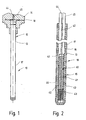
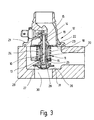
- thermostatic valve 12 While in FIGS. 1 and 2 alone a heater 10 is shown, the in particular for a thermostatic working element 11 of a thermostatic valve 12 is suitable, in Fig. 3, such a thermostatic valve 12 is schematic shown, which is a thermostatic working element 11, provided with a Heating device 10, comprising.
- the heating device 10 shown in FIGS. 1 and 2 has an electric heating cartridge 13 with holder 14 on.
- the heating cartridge 13 forms in this form a piston 15 of the Thermostatic working element 11.
- the heating element 13 has in detail Housing 16 in the form of a tubular sleeve 17, the lower in the drawing End is closed and at the top z. B. carries a flange 18.
- the Heating cartridge 13 is with this upper end portion with the flange 18 inside of the holder 14 was added.
- a housing 19 which is an expansion material 20, z.
- an expansion material 20 As a wax contains. With the upper end in the drawing this is Piston 15 supported immovably on a valve housing 21. At a Warming of the expansion material 20 and volume increase of this may be the Housing 19 of the thermostatic valve 12 in Fig. 3 down relative to not move displaceable piston 15 in the valve opening direction.
- the housing 19 carries a valve member 22 z. B. in the form of a valve disk, in the valve housing 21st a valve seat surface 23 is associated, which is dominated by the valve member 22.
- the Valve member 22 is acted upon by a closing spring 24 in the closing direction, the is supported with its upper end on the valve member 22 in the closing direction and with its opposite lower end to a support member 25 is seated on the Valve housing 21 fixed immovably and axially from the housing 19 slidably interspersed.
- a second Valve member 26 is at the lower end of the housing 19 slidably against the action of a spring 27 held by means of the second valve member 26 against a stop 28 of the Housing 19 is pressed.
- the spring 27 is supported by the other, the Valve member 26 opposite end to a shoulder 29 of the housing 19th from.
- the second valve member 26 is z. B. also designed as a valve plate and serves to control a bypass opening 30 in the valve housing 21.
- thermostatic valve 12 In the shown State of the thermostatic valve 12 is the main valve, namely Valve member 22, in the closed position, during the bypass valve, namely Valve member 26, located in the bypass opening 30 releasing position.
- Valve member 22 Upon heating of the expansion material 20 and volume increase this shifts the housing 19 relative to the piston 15 against the action of the closing spring 24 in Fig. 3 down, wherein the valve member 22 is increasingly the passage in the Area of the valve seat surface 23 releases, while the other valve member 26th increasingly reduces the passage through the bypass opening 30 up to the Closure of the bypass opening 30 by seating the valve member 26 at a associated valve seat 31.
- the heating element 13 forming the piston 15 contains within the housing 16 an electrical heating element 40, which has at least one heating conductor 41, which consists of at least one wound on a support 42 heating wire 43.
- This electrical heating element 40 is via lead-out electrical lines 44, 45 from a not further shown electrical power source, for. From the Vehicle electrical system of the vehicle, in which the thermostatic valve 12 is installed, can be fed.
- the carrier 42 with heating conductor 41 is surrounded by a sheath, 46, from the Housing 16 is enclosed.
- a thermostatic working element with conventional, not heated piston 15 set so that the thermostatic valve 12 only at a Temperature of about 100 ° C in the area of its main valve opens and with a Hub begins.
- the invention can be used in a particularly simple manner in that the at least one heating conductor 41 of the heating element 40 is such is designed that this a temperature-dependent resistance behavior has, in particular so that the heating conductor 41 during its switch-on determines the size of the current flowing through, in particular changes, in particular the heating power as a function of the changing Resistance regulates, namely reduced in particular with increasing resistance.
- the heating conductor 41 has z. B. on a positive temperature coefficient.
- the at least one heating wire 43 is made of such a material, the one has temperature-dependent resistance behavior.
- the Heating device 10 may be designed so that the heating conductor 41 in a lower Temperature range below the response temperature of the thermostatic Working elements 11 is, for heating in terms of faster and / or earlier and / or further opening of the thermostatic valve 12, in particular temperature-dependent is switchable.
- the arrangement z. B. be made so that the Heating conductor 41 in a temperature range of the ambient temperature of the thermostatic working element 11 from already about 0 ° C to about 50 ° C. in particular temperature-dependent is switched on. Because of that it is possible, even at low temperatures below the threshold of the thermostatic working element 11, an opening of the main valve with Valve member 22 to achieve in that in this lower temperature range more heating power is introduced into the piston 15.
- the electric heating cartridge 13 thus allows a variable power such that in the lower Temperature range is introduced high power, thus opening the Thermostatic valve 12 already at lower temperatures, and also one fast valve opening, done. It is also achievable that the thermostatic valve 12 opens faster at higher temperatures, with rising Coolant temperature then the introduced heating power is automatically reduced and thereby reduces the resulting in the heating cartridge 13 temperature , which reduces the risk of damage to the thermostatic Working elements 11, in particular individual components of this, such. B. of Sealing plug that seals the passage in the housing 19 for the piston 15, is avoided. Because of this, it is thus achieved that the thermostatic Working element 11 through the heating wire 43, which automatically through the heating power can regulate the temperature-dependent changing resistance, automatically regulates the required heating capacity. Thus it is not necessary that in one Control unit of an internal combustion engine, a corresponding power control function is held up.
- the invention is for. B. applicable with advantage in a thermostatic valve 12, the - starting from a cold internal combustion engine - the coolant circuit at Startup and warm-up of the internal combustion engine can be completely prevented.
- the heating conductor 41 in the range from about 0 ° C to is about 50 ° C, is in this lower temperature range due to the special design of the heating conductor 41 a high heating power introduced to the thermostatic valve 12 to open even at such low temperatures already and at higher temperatures to bring about a faster opening, so that then with valve opening, the internal coolant circulation can begin.
- the heating conductor 41 reduces the heating power due to increasing Resistance automatically, causing components of the working element 11 none Risk of damage.
Landscapes
- Physics & Mathematics (AREA)
- General Physics & Mathematics (AREA)
- Engineering & Computer Science (AREA)
- Automation & Control Theory (AREA)
- Temperature-Responsive Valves (AREA)
- Control Of Resistance Heating (AREA)
Applications Claiming Priority (2)
| Application Number | Priority Date | Filing Date | Title |
|---|---|---|---|
| DE2003160169 DE10360169A1 (de) | 2003-12-20 | 2003-12-20 | Heizeinrichtung, insbesondere für ein thermostatisches Arbeitselement eines Thermostatventils |
| DE10360169 | 2003-12-20 |
Publications (2)
| Publication Number | Publication Date |
|---|---|
| EP1545158A2 true EP1545158A2 (fr) | 2005-06-22 |
| EP1545158A3 EP1545158A3 (fr) | 2005-10-19 |
Family
ID=34485550
Family Applications (1)
| Application Number | Title | Priority Date | Filing Date |
|---|---|---|---|
| EP04027825A Withdrawn EP1545158A3 (fr) | 2003-12-20 | 2004-11-24 | Dispositif de chauffage, notamment pour élément fonctionnel thermostatique d'une valvule d'un thermostat |
Country Status (2)
| Country | Link |
|---|---|
| EP (1) | EP1545158A3 (fr) |
| DE (1) | DE10360169A1 (fr) |
Cited By (4)
| Publication number | Priority date | Publication date | Assignee | Title |
|---|---|---|---|---|
| EP2630351A1 (fr) * | 2010-10-22 | 2013-08-28 | Kirpart Otomotiv Parçalari Sanayi Ve Ticaret Anonim Sirketi | Thermostat chauffé électriquement et commandé par un plan par application d'un élément chauffant ptc |
| CN103796350A (zh) * | 2012-12-14 | 2014-05-14 | 杜志刚 | 带压二氧化碳电热装置方法 |
| WO2014090986A1 (fr) * | 2012-12-14 | 2014-06-19 | Vernet | Ensemble de chauffage pour une vanne thermostatique et procédé de fabrication correspondant, ainsi que vanne thermostatique comportant un tel ensemble |
| CN107693153A (zh) * | 2017-11-22 | 2018-02-16 | 四川大学 | 专用于对口腔修复使用的防烫伤蜡堤固定器 |
Families Citing this family (3)
| Publication number | Priority date | Publication date | Assignee | Title |
|---|---|---|---|---|
| DE102010001321B4 (de) | 2010-01-28 | 2013-09-26 | Brose Fahrzeugteile Gmbh & Co. Kommanditgesellschaft, Coburg | Kühlmittelkreislauf für einen Verbrennungsmotor eines Fahrzeugs |
| DE202010012135U1 (de) | 2010-09-02 | 2010-11-18 | Türk & Hillinger GmbH | Heizvorrichtung mit Dehnstoff-Arbeitselement |
| FR3086989B1 (fr) * | 2018-10-05 | 2020-10-23 | Novares France | Vanne thermostatique et vehicule comprenant cette vanne |
Family Cites Families (5)
| Publication number | Priority date | Publication date | Assignee | Title |
|---|---|---|---|---|
| GB1502479A (en) * | 1974-11-20 | 1978-03-01 | Matsushita Electric Industrial Co Ltd | Sealed thermostatic electric resistance heaters |
| DE3709285A1 (de) * | 1987-03-20 | 1988-09-29 | Tuerk & Hillinger Gmbh | Elektrische heizpatrone mit in sich unterschiedlicher leistungsabgabe |
| DE3826660A1 (de) * | 1988-08-05 | 1990-02-08 | Tuerk & Hillinger Gmbh | Elektrische heizpatrone mit selbstregelung |
| DE9105021U1 (de) * | 1990-11-17 | 1991-06-20 | Gustav Wahler Gmbh U. Co, 7300 Esslingen | Thermostatventil zur Regelung der Temperatur der Kühlflüssigkeit einer Brennkraftmaschine |
| DE10110185B9 (de) * | 2001-03-02 | 2013-05-02 | Eichenauer Heizelemente Gmbh & Co. Kg | Beheizbares Dehnstoffelement |
-
2003
- 2003-12-20 DE DE2003160169 patent/DE10360169A1/de not_active Ceased
-
2004
- 2004-11-24 EP EP04027825A patent/EP1545158A3/fr not_active Withdrawn
Cited By (9)
| Publication number | Priority date | Publication date | Assignee | Title |
|---|---|---|---|---|
| EP2630351A1 (fr) * | 2010-10-22 | 2013-08-28 | Kirpart Otomotiv Parçalari Sanayi Ve Ticaret Anonim Sirketi | Thermostat chauffé électriquement et commandé par un plan par application d'un élément chauffant ptc |
| CN103796350A (zh) * | 2012-12-14 | 2014-05-14 | 杜志刚 | 带压二氧化碳电热装置方法 |
| WO2014090986A1 (fr) * | 2012-12-14 | 2014-06-19 | Vernet | Ensemble de chauffage pour une vanne thermostatique et procédé de fabrication correspondant, ainsi que vanne thermostatique comportant un tel ensemble |
| FR2999861A1 (fr) * | 2012-12-14 | 2014-06-20 | Vernet | Ensemble de chauffage pour une vanne thermostatique et procede de fabrication correspondant, ainsi que vanne thermostatique comportant un tel ensemble |
| CN105009685A (zh) * | 2012-12-14 | 2015-10-28 | 韦内特公司 | 用于恒温阀的加热组件及相应的生产方法,和包含该组件的恒温阀 |
| CN105009685B (zh) * | 2012-12-14 | 2017-04-12 | 韦内特公司 | 用于恒温阀的加热组件及相应的生产方法,和包含该组件的恒温阀 |
| US9844097B2 (en) | 2012-12-14 | 2017-12-12 | Vernet | Heating assembly for a thermostatic valve and corresponding production method, and a thermostatic valve comprising such an assembly |
| CN107693153A (zh) * | 2017-11-22 | 2018-02-16 | 四川大学 | 专用于对口腔修复使用的防烫伤蜡堤固定器 |
| CN107693153B (zh) * | 2017-11-22 | 2023-09-26 | 四川大学 | 专用于对口腔修复使用的防烫伤蜡堤固定器 |
Also Published As
| Publication number | Publication date |
|---|---|
| DE10360169A1 (de) | 2005-07-28 |
| EP1545158A3 (fr) | 2005-10-19 |
Similar Documents
| Publication | Publication Date | Title |
|---|---|---|
| DE69922402T2 (de) | Verfahren und gerät zur steuerung eines kraftstoffeinspritzventils mit formgedächtniselement | |
| DE102017011428B4 (de) | Kühlsystem und Fahrzeug mit einem solchen Kühlsystem | |
| EP0893581B1 (fr) | Vanne à voies multiples | |
| DE4330215A1 (de) | Kühlanlage für einen Verbrennungsmotor eines Kraftfahrzeuges mit einem Ventil | |
| DE29500897U1 (de) | Thermostatventil | |
| DE10253469A1 (de) | Thermostatventil für ein Kühlsystem einer Brennkraftmaschine | |
| DE19728814A1 (de) | Kühlanlage für einen Verbrennungsmotor eines Kraftfahrzeuges | |
| DE102004020589A1 (de) | Temperaturabhängige Strömungsregelventile für Motorkühlsysteme | |
| DE102012113164A1 (de) | Glühkerze und elektrischer thermostat mit derselben | |
| DE4325975B4 (de) | Thermostatventil | |
| EP0746807A1 (fr) | Soupape de thermostat destinee au circuit de refroidissement d'un moteur a combustion interne | |
| DE10226904A1 (de) | Motorkühlsystem mit zwei Thermostaten | |
| DE10250157B4 (de) | Kühlvorrichtung für einen Verbrennungsmotor | |
| DE4106081A1 (de) | Thermostatventil zur regelung der temperatur der kuehlfluessigkeit einer brennkraftmaschine, insbesondere eines kraftfahrzeugmotors | |
| DE202016008471U1 (de) | Thermostat-Aufbau mit variablem Ventilsitz | |
| EP1545158A2 (fr) | Dispositif de chauffage, notamment pour élément fonctionnel thermostatique d'une valvule d'un thermostat | |
| EP0484624A1 (fr) | Soupape thermostatique pour la régulation de la température du liquide de refroidissement d'un moteur à combustion interne | |
| DE19500648B4 (de) | Kühlanlage für einen Verbrennungsmotor eines Kraftfahrzeuges mit einem Thermostatventil | |
| DE2923523A1 (de) | Thermostatisches regelventil zum einhalten eines im wesentlichen konstanten sollwertes der betriebstemperatur eines fluessigen kuehlmittels einer brennkraftmaschine | |
| DE2360157A1 (de) | System zur steuerung der startvorrichtung eines vergasers | |
| DE102009003894A1 (de) | Flüssigkeitskühlsystem für einen Motor mit innerer Verbrennung | |
| DE4123866C2 (de) | Dieselvorwärmer für Motoren, insbesondere Fahrzeugmotoren | |
| DE20321257U1 (de) | Heizeinrichtung, insbesondere für ein thermostatisches Arbeitselement eines Thermostatventils | |
| EP2551569B1 (fr) | Soupape thermostatique | |
| DE202016008470U1 (de) | Thermostatanordnung mit variablem Ventilsitz |
Legal Events
| Date | Code | Title | Description |
|---|---|---|---|
| PUAI | Public reference made under article 153(3) epc to a published international application that has entered the european phase |
Free format text: ORIGINAL CODE: 0009012 |
|
| AK | Designated contracting states |
Kind code of ref document: A2 Designated state(s): AT BE BG CH CY CZ DE DK EE ES FI FR GB GR HU IE IS IT LI LU MC NL PL PT RO SE SI SK TR |
|
| AX | Request for extension of the european patent |
Extension state: AL HR LT LV MK YU |
|
| PUAL | Search report despatched |
Free format text: ORIGINAL CODE: 0009013 |
|
| AK | Designated contracting states |
Kind code of ref document: A3 Designated state(s): AT BE BG CH CY CZ DE DK EE ES FI FR GB GR HU IE IS IT LI LU MC NL PL PT RO SE SI SK TR |
|
| AX | Request for extension of the european patent |
Extension state: AL HR LT LV MK YU |
|
| RIC1 | Information provided on ipc code assigned before grant |
Ipc: 7H 01C 7/02 B Ipc: 7H 05B 3/46 A |
|
| 17P | Request for examination filed |
Effective date: 20060304 |
|
| AKX | Designation fees paid |
Designated state(s): DE FR GB IT SE |
|
| STAA | Information on the status of an ep patent application or granted ep patent |
Free format text: STATUS: THE APPLICATION IS DEEMED TO BE WITHDRAWN |
|
| 18D | Application deemed to be withdrawn |
Effective date: 20060808 |