EP1545034A2 - Digitale Videoüberlagerung in passiven optischen Netzwerken - Google Patents
Digitale Videoüberlagerung in passiven optischen Netzwerken Download PDFInfo
- Publication number
- EP1545034A2 EP1545034A2 EP04027264A EP04027264A EP1545034A2 EP 1545034 A2 EP1545034 A2 EP 1545034A2 EP 04027264 A EP04027264 A EP 04027264A EP 04027264 A EP04027264 A EP 04027264A EP 1545034 A2 EP1545034 A2 EP 1545034A2
- Authority
- EP
- European Patent Office
- Prior art keywords
- digital video
- video signal
- signal
- video signals
- ont
- Prior art date
- Legal status (The legal status is an assumption and is not a legal conclusion. Google has not performed a legal analysis and makes no representation as to the accuracy of the status listed.)
- Withdrawn
Links
- 230000003287 optical effect Effects 0.000 title claims abstract description 36
- 238000000034 method Methods 0.000 claims description 19
- 238000010586 diagram Methods 0.000 description 14
- 238000013144 data compression Methods 0.000 description 8
- 238000005516 engineering process Methods 0.000 description 4
- 238000011144 upstream manufacturing Methods 0.000 description 3
- 239000000969 carrier Substances 0.000 description 2
- 238000001914 filtration Methods 0.000 description 2
- 238000009432 framing Methods 0.000 description 2
- 238000007726 management method Methods 0.000 description 2
- 239000013307 optical fiber Substances 0.000 description 2
- 230000003595 spectral effect Effects 0.000 description 2
- 238000001228 spectrum Methods 0.000 description 2
- 230000002411 adverse Effects 0.000 description 1
- 238000013475 authorization Methods 0.000 description 1
- 230000005540 biological transmission Effects 0.000 description 1
- 238000012937 correction Methods 0.000 description 1
- 238000011161 development Methods 0.000 description 1
- 230000009977 dual effect Effects 0.000 description 1
- 239000000835 fiber Substances 0.000 description 1
- 239000000463 material Substances 0.000 description 1
- 238000012986 modification Methods 0.000 description 1
- 230000004048 modification Effects 0.000 description 1
- 238000012545 processing Methods 0.000 description 1
- 230000008707 rearrangement Effects 0.000 description 1
- 238000006467 substitution reaction Methods 0.000 description 1
- 238000012546 transfer Methods 0.000 description 1
Images
Classifications
-
- H—ELECTRICITY
- H04—ELECTRIC COMMUNICATION TECHNIQUE
- H04J—MULTIPLEX COMMUNICATION
- H04J14/00—Optical multiplex systems
- H04J14/02—Wavelength-division multiplex systems
- H04J14/0226—Fixed carrier allocation, e.g. according to service
-
- H—ELECTRICITY
- H04—ELECTRIC COMMUNICATION TECHNIQUE
- H04J—MULTIPLEX COMMUNICATION
- H04J14/00—Optical multiplex systems
- H04J14/02—Wavelength-division multiplex systems
- H04J14/0227—Operation, administration, maintenance or provisioning [OAMP] of WDM networks, e.g. media access, routing or wavelength allocation
- H04J14/0228—Wavelength allocation for communications one-to-all, e.g. broadcasting wavelengths
- H04J14/023—Wavelength allocation for communications one-to-all, e.g. broadcasting wavelengths in WDM passive optical networks [WDM-PON]
- H04J14/0232—Wavelength allocation for communications one-to-all, e.g. broadcasting wavelengths in WDM passive optical networks [WDM-PON] for downstream transmission
-
- H—ELECTRICITY
- H04—ELECTRIC COMMUNICATION TECHNIQUE
- H04J—MULTIPLEX COMMUNICATION
- H04J14/00—Optical multiplex systems
- H04J14/02—Wavelength-division multiplex systems
- H04J14/0227—Operation, administration, maintenance or provisioning [OAMP] of WDM networks, e.g. media access, routing or wavelength allocation
- H04J14/0238—Wavelength allocation for communications one-to-many, e.g. multicasting wavelengths
-
- H—ELECTRICITY
- H04—ELECTRIC COMMUNICATION TECHNIQUE
- H04J—MULTIPLEX COMMUNICATION
- H04J14/00—Optical multiplex systems
- H04J14/02—Wavelength-division multiplex systems
- H04J14/0227—Operation, administration, maintenance or provisioning [OAMP] of WDM networks, e.g. media access, routing or wavelength allocation
- H04J14/0241—Wavelength allocation for communications one-to-one, e.g. unicasting wavelengths
- H04J14/0242—Wavelength allocation for communications one-to-one, e.g. unicasting wavelengths in WDM-PON
- H04J14/0245—Wavelength allocation for communications one-to-one, e.g. unicasting wavelengths in WDM-PON for downstream transmission, e.g. optical line terminal [OLT] to ONU
- H04J14/0247—Sharing one wavelength for at least a group of ONUs
-
- H—ELECTRICITY
- H04—ELECTRIC COMMUNICATION TECHNIQUE
- H04J—MULTIPLEX COMMUNICATION
- H04J14/00—Optical multiplex systems
- H04J14/02—Wavelength-division multiplex systems
- H04J14/0227—Operation, administration, maintenance or provisioning [OAMP] of WDM networks, e.g. media access, routing or wavelength allocation
- H04J14/0241—Wavelength allocation for communications one-to-one, e.g. unicasting wavelengths
- H04J14/0242—Wavelength allocation for communications one-to-one, e.g. unicasting wavelengths in WDM-PON
- H04J14/0249—Wavelength allocation for communications one-to-one, e.g. unicasting wavelengths in WDM-PON for upstream transmission, e.g. ONU-to-OLT or ONU-to-ONU
- H04J14/0252—Sharing one wavelength for at least a group of ONUs, e.g. for transmissions from-ONU-to-OLT or from-ONU-to-ONU
-
- H—ELECTRICITY
- H04—ELECTRIC COMMUNICATION TECHNIQUE
- H04N—PICTORIAL COMMUNICATION, e.g. TELEVISION
- H04N7/00—Television systems
- H04N7/22—Adaptations for optical transmission
Definitions
- the present invention relates in general to a passive optical network that is capable of delivering video, voice and data to end-users.
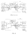
- FIGURE 1 there is a block diagram that shows the basic components of a traditional PON 100 that is capable of delivering video, voice and data to an end-user 102 (one shown).
- the PON 100 is made from well known components which include an optical line termination module (OLT) 104, an optical distribution network (ODN) 106 and multiple optical network termination modules (ONTs) 108 (five shown).
- OLT optical line termination module
- ODN optical distribution network
- ONTs optical network termination modules
- the OLT 104 interfaces with a public switched telephone network (PSTN) 110 which enables voice to be delivered to the end-user 102 via a plain old telephone service (POTS) device 112 (e.g., telephone 112).
- PSTN public switched telephone network
- POTS plain old telephone service
- the OLT 104 interfaces with an asynchronous transfer mode/internet protocol (ATM/IP) network 114 which enables data to be delivered to the end-user 102 via a personal computer (PC) 116.
- ATM/IP asynchronous transfer mode/internet protocol
- the voice and data are transmitted to the end-user 102 on a 1480-1500nm band (e.g., 1490nm center-wavelength) and received from the end-user 102 on a 1260-1360nm band (e.g., 1310nm center-wavelength).
- the OLT 104 interfaces with a video provider 118 which enables video to be delivered to the end-user 102 via a television 120.
- a brief description is provided below that describes two known ways that the PON network 100 can be configured to deliver video to the end-user 102.
- WDM wavelength division multiplexing
- ITU-T G983.1 to 8 specification There are several drawbacks associated with this particular traditional PON 100 including for example: (1) the WDM analog video overlay 122 is "analog"; (2) the WDM analog video overlay 122 does not support evolutions towards video-on-demand or high definition television (HDTV) very well; and (3) the WDM analog video overlay 122 is not compatible with inband video delivery systems that use for example an xDSL infrastructure.
- Another disadvantage is the cost of the WDM analog video overlay 122 where high power optics are required at the OLT 104 to feed the analog video signal to the ONTs 108.
- the high power optics and their supporting amplifiers are expensive because they have high linearity requirements over a broad frequency range.
- a second known way of configuring the traditional PON 100 so it can deliver video in addition to voice and data to end-users 102 is to integrate inband video streaming equipment 124 into the PON 100.
- the main drawbacks associated with this particular traditional PON 100 is that the inband video streaming equipment 124 needs a complicated multicast protocol to avoid duplication of broadcast streams.
- the inband video streaming equipment 124 needs an enormous bandwidth to distribute the video signals.
- the complicated multicast protocol and the enormous bandwidth requirements have an adverse impact on the development resources and potential cost of the inband video streaming equipment 124.
- there is a need for a PON network that addresses and solves the aforementioned drawbacks associated with delivering video to an end-user using the traditional PONs.
- the present invention includes a PON capable of using a WDM 1550nm digital video overlay to deliver a digital video signal (e.g., analog broadcasted signal) from a video head-end to an end-user.
- the PON is also capable of transmitting voice and data on a 1480-1500nm band to the end-user and further capable of receiving voice and data on a 1260-1360nm band from the end-user.
- the present invention also includes a set-top box and several methods associated with using the PON.
- FIGURE 2 there is a block diagram that shows a PON 200 that is capable of delivering video, voice and data to an end-user 202 in accordance with the present invention.
- the PON 200 includes an OLT 204, an ODN 206 and multiple ONTs 208 (five shown).
- the OLT 204 interfaces with a PSTN 210 which enables voice to be delivered to the end-user 202 via a POTS device 212 (e.g., telephone 212).
- POTS device 212 e.g., telephone 212).
- the OLT 204 also interfaces with an ATM/IP network 214 which enables data and inband video to be delivered to the end-user 202 via a PC 216.
- the voice and data are transmitted to the end-user 202 on a 1480-1500nm band (e.g., 1490nm wavelength) and received from the end-user 202 on a 1260-1360nm band (e.g., 1310nm wavelength).
- the PON 200 uses a WDM digital video overlay 218 to deliver a digital video signal 220 on a 1550nm wavelength (for example) from a video head-end 219 to a television 221 used by the end-user 202.
- the PON 200 utilizes WDM filters, a modulator (e.g., QAM modulator), a data compression protocol (e.g., MPEG2, MPEG4) and a transport protocol (e.g., Ethernet).
- WDM filters e.g., QAM modulator
- a data compression protocol e.g., MPEG2, MPEG4
- a transport protocol e.g., Ethernet
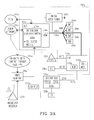
- the PON 200a includes an OLT 204a, an ODN 206a and multiple ONTs 208a (five shown). Certain details associated with the components within the OLT 204a, ODN 206a and ONT 208a are well known in the industry. Therefore, for clarity, the description provided below in relation to the PON 200a omits those well known details and components that are not necessary to understand the present invention.
- the OLT 204a interfaces with a PSTN 210a which enables voice to be delivered to the end-user 202a via a POTS device 212a (e.g., telephone 212a).
- the OLT 204a also interfaces with an ATM/IP network 214a which enables data to be delivered to the end-user 202a via a PC 216a.
- the OLT 204a interfaces with a video-head end 219a to deliver one or more digital video signals 220a to a set-top box 226a and display 228a (e.g., television 228a) which are used by the end-user 202a.
- the video-head end 219a is the video source for the PON 200a.
- the video-head end 219a interfaces with a broadcast receiver 230a and an enhanced video content provider 232a.
- the broadcast receiver 230a is used to receive analog and digital broadcasted television signals (or high definition television signals).
- the analog broadcasted television signals need to be digitized.
- the digitized analog and the digital broadcasted television signals are encoded with an appropriate video data compression encoding scheme such as MPEG2 or MPEG4 (for example).
- the digital signals 220a are then transported to a distribution device 234a that can be co-located with the OLT 204a.
- the transport protocol can be Gigabit Ethernet (for example).
- the video content provider 232a can supply digital video signals 220a (including high definition television signals 220a) from services like Video On Demand (VoD) and Pay Per View (PPV).
- the video content provider 232a typically supplies digital video signals 220a that are already digitized and encoded in the appropriate format.
- the video-head end 219a may need to encrypt the VoD and PPV digital video signals 220a to ensure privacy and to prevent unauthorized end-users 202a from viewing the material without payment.
- the video head-end 219a may need to receive information (authorization and authentication information) about the appropriate end-users 202a to determine the destinations of those end-users 202a before it can supply VoD and PPV digital video signals 220a. This information could be provided via an upstream PON data link from the ONT 208a (see FIGURE 3D).
- the video-head end 219a interfaces with the distribution device 234a which is typically co-located with the OLT 204a.
- the distribution device 234a includes an optical transmitter 236a that transmits the digital video signals 220a to a WDM filter 238a.
- the optical transmitter 236a feeds the WDM filter 238a using the appropriate wavelength (e.g., 1550nm center-wavelength) to fit into the WDM scheme specified by the PON 200a.
- 1550nm center-wavelength e.g., 1550nm center-wavelength
- the distribution device 234a may need to perform port selection tasks to select the correct ports which select the correct PON trees that serve the appropriate end-users 202a. This information could be provided by the video head-end 219a.
- the WDM filter 238a receives (step 302 in FIGURE 3B) the digital video signals 220a (e.g. MPEG2 encoded PPV digital video signals 220a) from the video-head end 219a and the distribution device 234a. Then the WDM filter 238a multiplexes (step 304) the digital video signals 220a and outputs (step 306) a multiplexed digital video signal 220a on an optical fiber 239a to the ONT 208a.
- the ONT 208a and in particular a WDM filter 240a receives and demultiplexes (step 308) the multiplexed digital video signal 220a from the data signal and voice signal.
- the WDM filter 240a then outputs demultiplexed digital video signals 220a to a modulator 242a (e.g., QAM modulator 242a) shown located in the ONT 208a.
- the modulator 242a receives and modulates (step 310) the demultiplexed digital video signals 220a and then outputs (step 312) the modulated digital video signals 220a over a co-axial cable 243 (for example) to the set-top box 226a.
- the set-top box 226a includes a tuner 244a that downconverts to baseband a selected carrier of one of the modulated digital video signals 220a based on a channel selected by the end-user 202a.
- the set-top box 226a also includes a demodulator 246a (e.g., QAM demodulator 246a) that translates the baseband video signal 220a back into a digital video signal 220a.
- This digital video signal 220a is then decoded with a decoder 248a (e.g., MPEG decoder 248a).
- the decoded video signal 220a is fed over a co-axial cable (for example) to a video port or S-video port in the television 228a.
- the decoded digital video signal 220a can be RF modulated (NTSC or PAL) and sent to the television 228a.
- NTSC RF modulated
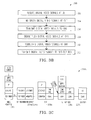
- FIGURE 3C shows the protocol stack for the PON 200a.
- FIGURE 3C there is a diagram illustrating in greater detail exemplary protocol stacks associated with the video-head end 219a, the PON 200a, the set-top box 226a and the television 228a. It should be understood that for clarity many of the details associated with each protocol are well known to those skilled in the art and as such are not described in detail herein.
- the video-head end 219a has a protocol stack which includes at least the following layers:
- the video-head end 219a is connected to the OLT 204a which has a protocol stack with at least the following layers: OLT 204a Ethernet Ethernet P2P Fiber WDM/PON
- This exemplary protocol stack indicates that the OLT 204a converts the physical layer from point-2-point fiber (such as Gigabit Ethernet) to WDM over PON while the layer above (such as Ethernet) remains untouched.
- the OLT 204a is connected to the ONT 208a which has a protocol stack with at least the following layers:
- This exemplary protocol stack indicates that the transport layers (IP and Ethernet) are terminated in the ONT 208a and the video channels 220a are modulated and then transported further using COAX.
- the ONT 208a is connected to the set-top box 226a which has a protocol stack with at least the following layers:
- the set-top box 226a can be a legacy set-top box 226a such as "commodity" satellite receiver set-top box which has a large bandwidth capability. If a legacy set-top box 226a is used then the modulator 242a would need to be selected to interface with the set-top box 226a.
- the set-top box 226a is connected to the television 228a which has a protocol stack with at least the following layers:
- connection between the video-head end 219a and the ONT 208a is basically Ethernet (with on top of that maybe IP).
- This architecture has some advantages such as:
- a drawback of the architecture shown in FIGURE 3C is that each ONT 208a needs to have a modulator 242a (e.g., QAM video modulator 242a) designed to interface with the set-top box 226a (e.g., "commodity" set-top box 226a). And, if a QAM video modulator 242a is used then it needs to model somewhere between 40 to 150 carriers which involves a lot of digital signal processing.
- a possible solution to the drawback associated with the QAM modulator 242a would be to only modulate the digital video signals 220a (channels) that the set-top box 226a has selected to demodulate but this would require a management channel between the set-top box 226a and ONT 208a.
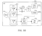
- FIGURE 3D there is shown a block diagram that illustrates in greater detail the basic components of the ONT 208a.
- Certain details associated with the components like the E/O receiver 250a, the PON-PHY (such as BPON, EPON or GPON) 252a, the PON TC 254a, the Ethernet component 256a and the CODEC & SLICS 258a within the ONT 208a are known in the industry Therefore, for clarity, the description provided below in relation to the ONT 208a omits details about those components and other components not necessary to understand the present invention.
- the ONT 208a in addition to components 250a, 252a, 254a, 256a and 258a includes the WDM filter 240a which is used to separate the voice/data upstream and downstream from the digital video signal overlay downstream.
- the ONT 208a also includes a digital video receiver 260a that receives the digital video signal 220a on the 1550nm wavelength (for example) and synchronizes the datastream of the received digital video signal 220a using basic framing applied on a physical layer. Once synchronization is established, the digital video receiver 260a filters the digital video signal 220a that is then sent to the modulator 242a which manipulates the video signal 220a so that is interoperable with the set-top box 226a.
- the digital video receiver 260a may need to receive information from the inband PON data stream (e.g., Ethernet device 256a) so that it can de-encrypt the VoD or PPV digital video signal 220a.
- the set-top box 226a can decode the encrypted VoD and PPV video signals 220a.
- the modulator 242a can be a QAM modulator 242a which is able to modulate the digital video signals 220a into the available frequency spectrum so they can be transported to the set-top box 226a.
- the capacity of a single QAM modulated signal depends on constellation size and symbol-rate. And, that a higher constellation size is more spectral efficient and as such allows more data capacity. However a higher constellation size also requires a larger signal-to-noise (SNR) ratio to maintain the desired SNR ratio.
- SNR signal-to-noise
- the QAM symbol rate can be very large (e.g., up to 45Msps) which allows for very small constellation sizes.
- BPSK and QPSK are other modulation schemes that could be used this environment.
- the available bandwidth would be more restrictive.
- the QAM modulated carriers are restricted to 6, 7 or 8 MHz in order to remain compatible with the analog RF modulated NTSC, PAL or SECAM video channels.
- 64-QAM or 256 QAM are the typical modulation schemes that can be used to achieve a higher spectral efficiency.
- the choice of modulation schemes such as QAM, BPSK or QPSK used by the modulator 242a can be dictated by the type of set-top box 226a selected to be used in the present invention.
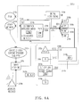
- the PON 200b includes an OLT 204b, an ODN 206b and multiple ONTs 208b (five shown). Again, certain details associated with the components within the OLT 204b, ODN 206b and ONT 208b are well known in the industry. Therefore, for clarity, the description provided below in relation to the PON 200b omits those well known details and components that are not necessary to understand the present invention.
- the OLT 204b interfaces with a PSTN 210b which enables voice to be delivered to the end-user 202b via a POTS device 212b (e.g., telephone 212b).
- the OLT 204b also interfaces with an ATM/IP network 214b which enables data to be delivered to the end-user 202b via a PC 216b.
- the OLT 204b interfaces with a video-head end 219b (similar to video-head end 219a) to deliver one or more digital video signals 220b to the end-user 202b via a set-top box 226b (similar to set-top box 226a) and a display 228b (e.g., television 228b).
- the OLT 204b and in particular a co-located modulator 242b receives (step 402 in FIGURE 4B) the digital video signals 220b (e.g. MPEG2 encoded PPV digital video signals 220b) from the video-head end 219b and the distribution device 234b. Then the modulator 242b modulates (step 404) the digital video signals 220b and outputs modulated digital video signals 220b to the WDM filter 238b.
- the digital video signals 220b e.g. MPEG2 encoded PPV digital video signals 220b
- the WDM filter 238b multiplexes (step 406) the modulated digital video signals 220b and outputs (step 408) a multiplexed modulated digital video signal 220b on an optical fiber 239b to the ONT 208b.
- the ONT 208b and in particular a WDM filter 240b receives and demultiplexes (step 410) the multiplexed modulated digital video signal 220a from the data signal and voice signal.
- the WDM filter 240a then outputs (step 412) the demultiplexed modulated digital video signals 220b over a co-axial cable (for example) to the set-top box 226b.
- the set-top box 226b includes a tuner 244b that downconverts to baseband a selected carrier of one of the modulated digital video signals 220b based on a channel selected by the end-user 202b.
- the set-top box 226b also includes a demodulator 246b (e.g., QAM demodulator 246b) that translates the baseband video signal 220b back into a digital video signal 220b.
- This digital video signal 220b is then decoded with a decoder 248b (e.g., MPEG decoder 248b).
- the decoded video signal 220b is fed over a co-axial cable (for example) to a video port or S-video port in the television 228b.
- the decoded digital video signal 220b can be RF modulated (NTSC or PAL) and sent to the television 228b.
- NTSC RF modulated
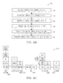
- FIGURE 4C shows the protocol stack for the PON 200b.
- FIGURE 4C there is a diagram illustrating in greater detail exemplary protocol stacks associated with the video-head end 219b, the PON 200b, the set-top box 226b and the television 228b. It should be understood that for clarity many of the details associated with each protocol are well known to those skilled in the art and as such are not described in detail herein.
- the video-head end 219b is associated with a protocol stack which includes at least the following layers:
- the video-head end 219b is connected to the OLT 204b which has a protocol stack with at least the following layers:
- the OLT 204b/distribution device 234b is connected to the ONT 208b which has a protocol stack with at least the following layers: ONT 208b WDM/PON COAX
- the ONT 208b is connected to the set-top box 226b which has a protocol stack with at least the following layers: Set-top box 226b Digital/Analog MPEG Decoding QAM Demodulation RF Modulation COAX COAX
- the set-top box 226b can be a legacy set-top box 226b such as "commodity" satellite receiver set-top box which has a large bandwidth capability.
- the set-top box 226b is connected to the television 228b which has a protocol stack with at least the following layers:
- FIGURE 4C it can be seen that the QAM complexity is reduced in PON 200b because one QAM modulator 242b is used by the OLT 204b as compared to the first embodiment of the PON 200a which has a QAM modulator 242a in each one of the ONTs 208a (see FIGURE 4A).
- One possible drawback of associating the QAM modulator 242b with the OLT 204b is that the linearity and SNR requirements are increased on the optical transmitter 236b that feeds the digital video signals 220b into the WDM filter 238b. Nevertheless these requirements are still quite relaxed as compared to the traditional PON 100 that uses the WDM analog video overlay 122 (see FIGURE 1).
- the PON 200b could use ONTs 208b that are similar to the ONTs used in the traditional PON 100 that uses the WDM analog video overlay 122 so long as the utilized spectrum by the centralized QAM modulator 242b associated with the OLT 204b corresponds to the band in the analog path which can be up to 550-750MHz for NTSC.
- the WDM digital video overlay can reuse mature technologies such as MPEG2 and MPEG4 for data-compression and Ethernet as a transport protocol. By reusing these technologies, the WDM digital video overlay can be implemented with minimal changes to the basic PON.
- MPEG2 is already used to compress digital video signals for satellite broadcast this means that the set-top box 226 can be the same as or similar to a traditional satellite set-top box.
- Gigabit Ethernet which has a payload of 1Gbps is already used to connect Local Area Networks (LANs) and IP switches this means that the distribution of digital video signals 220 could be implemented by reusing off-the shelf Gigabit Ethernet switches.
- Gigabit Ethernet it can deliver up to 250 TV channels or 50 HDTV channels or any linear combination of these two simply by allocating 4Mbps for a normal TV channel and 20Mbps for a HDTV channel. And, as the data compression technology evolves it is believed that the next generation Ethernet standard will be able to deliver 10Gbps which enables the amount of channels that can be delivered via this infrastructure to grow dramatically over the next few years.
- the PON 200 can reuse some parts of the IEEE EFM EPON specification.
- the EPON specification requires that every ONT receives the full digital signal content.
- the PON 200 reuses the ONT that is based on the EPON specification then the specialized content like VoD and PPV digital video signals 220 destined for specific users 202 would have to be filtered in the ONT 208.
- this is not believed to be a security risk since the same digital signal broadcast concept with content filtering in the ONT is also applied for the data path in both the EPON and APON specifications.
- the architecture of the PON 200 can be characterized as a "dumb”, always on downstream video channel or as a big "dumb” bitpipe if you will, with basic framing on the Physical layer to enable each ONT 208 to 'lock in' without requiring direct feedback to the digital OLT 204.
- This "dumb" bitpipe can be considered as a satellite replacement delivery vehicle.
Landscapes
- Engineering & Computer Science (AREA)
- Signal Processing (AREA)
- Computer Networks & Wireless Communication (AREA)
- Multimedia (AREA)
- Optical Communication System (AREA)
- Two-Way Televisions, Distribution Of Moving Picture Or The Like (AREA)
- Small-Scale Networks (AREA)
Applications Claiming Priority (2)
| Application Number | Priority Date | Filing Date | Title |
|---|---|---|---|
| US10/742,669 US20050138670A1 (en) | 2003-12-20 | 2003-12-20 | Digital video overlay for passive optical networks |
| US742669 | 2003-12-20 |
Publications (2)
| Publication Number | Publication Date |
|---|---|
| EP1545034A2 true EP1545034A2 (de) | 2005-06-22 |
| EP1545034A3 EP1545034A3 (de) | 2006-10-04 |
Family
ID=34523258
Family Applications (1)
| Application Number | Title | Priority Date | Filing Date |
|---|---|---|---|
| EP04027264A Withdrawn EP1545034A3 (de) | 2003-12-20 | 2004-11-17 | Digitale Videoüberlagerung in passiven optischen Netzwerken |
Country Status (3)
| Country | Link |
|---|---|
| US (1) | US20050138670A1 (de) |
| EP (1) | EP1545034A3 (de) |
| JP (1) | JP2005210688A (de) |
Cited By (4)
| Publication number | Priority date | Publication date | Assignee | Title |
|---|---|---|---|---|
| EP1608106A3 (de) * | 2004-06-01 | 2007-01-24 | Alcatel | System und Verfahren zur Verteilung der Videopakete in einem optischen Netzwerk |
| WO2007021507A1 (en) * | 2005-08-10 | 2007-02-22 | Tellabs Petaluma, Inc. | Fttp ip video overlay |
| WO2007122515A3 (en) * | 2006-04-26 | 2008-11-20 | Alcatel Lucent | Video signal processing apparatus and methods |
| CN114667051A (zh) * | 2022-05-25 | 2022-06-24 | 绍兴中科通信设备有限公司 | 抗干扰光模块 |
Families Citing this family (20)
| Publication number | Priority date | Publication date | Assignee | Title |
|---|---|---|---|---|
| WO2005076911A2 (en) * | 2004-02-06 | 2005-08-25 | Arris International, Inc. | Method and system for providing docsis service over a passive optical network |
| KR100582556B1 (ko) * | 2004-02-12 | 2006-05-22 | 한국전자통신연구원 | 통신 방송 융합 액세스 시스템과 그 방법 |
| US8014405B2 (en) * | 2004-03-10 | 2011-09-06 | At&T Intellectual Property I, L.P. | Upgrading ATM embedded networks to carry IP signals |
| JP2005354380A (ja) * | 2004-06-10 | 2005-12-22 | Fujikura Ltd | 光通信装置及び光通信システム |
| FR2872655A1 (fr) * | 2004-07-01 | 2006-01-06 | France Telecom | Reseau privatif multiservices et modules d'interface permettant de vehiculer, sur un tel reseau, des donnees sous differents formats |
| KR100606031B1 (ko) * | 2004-08-23 | 2006-07-28 | 삼성전자주식회사 | 아날로그 전화 서비스가 가능한 광통신 시스템 |
| US20060098632A1 (en) * | 2004-11-08 | 2006-05-11 | Johnson William A | System and method for integrated distribution of broadband services |
| EP1889390A2 (de) * | 2005-06-06 | 2008-02-20 | Intellambda Systems, Inc | Aggregierende optische netzwerkeinrichtung |
| US20070204309A1 (en) * | 2005-11-01 | 2007-08-30 | Tellabs Vienna, Inc. | Method and apparatus for preserving internet protocol video services across an optical network element reboot |
| JP4634290B2 (ja) * | 2005-11-29 | 2011-02-16 | 富士通株式会社 | 伝送装置 |
| JP2007201670A (ja) * | 2006-01-25 | 2007-08-09 | Hitachi Communication Technologies Ltd | 光伝送システム |
| KR100786040B1 (ko) | 2006-05-19 | 2007-12-17 | 한국과학기술원 | 높은 스펙트럼 효율을 구비한 전송 포맷을 이용하여 고속광신호 전송이 가능한 파장 분할 다중방식 수동형 광가입자망 |
| US8346095B2 (en) | 2009-12-07 | 2013-01-01 | Centurylink Intellectual Property Llc | System and method for providing multi-provider telecommunications services over a passive optical network |
| US10117006B2 (en) | 2010-03-31 | 2018-10-30 | Comcast Cable Communications, Llc | Hybrid fiber coaxial node |
| CN102256116A (zh) * | 2010-05-20 | 2011-11-23 | Tcl集团股份有限公司 | 平板电视的光纤接口及其信号传输方法 |
| US9942413B2 (en) | 2014-04-02 | 2018-04-10 | Centurylink Intellectual Property Llc | Multi-network access gateway |
| US9806844B2 (en) * | 2014-11-10 | 2017-10-31 | Perfectvision Manufacturing, Inc. | Electromagnetic signal transport and distribution system |
| US10250353B2 (en) * | 2014-11-10 | 2019-04-02 | Perfectvision Manufacturing, Inc. | Electromagnetic signal transport and distribution systems |
| US10397672B2 (en) | 2016-06-20 | 2019-08-27 | Cable Television Laboratories, Inc. | Systems and methods for intelligent edge to edge optical system and wavelength provisioning |
| US10200123B2 (en) * | 2016-06-20 | 2019-02-05 | Cable Television Laboratories, Inc. | System and methods for distribution of heterogeneous wavelength multiplexed signals over optical access network |
Citations (1)
| Publication number | Priority date | Publication date | Assignee | Title |
|---|---|---|---|---|
| US6385366B1 (en) | 2000-08-31 | 2002-05-07 | Jedai Broadband Networks Inc. | Fiber to the home office (FTTHO) architecture employing multiple wavelength bands as an overlay in an existing hybrid fiber coax (HFC) transmission system |
Family Cites Families (11)
| Publication number | Priority date | Publication date | Assignee | Title |
|---|---|---|---|---|
| JPH11196409A (ja) * | 1998-01-06 | 1999-07-21 | Matsushita Electric Ind Co Ltd | 光通信システム |
| JP3937564B2 (ja) * | 1998-03-24 | 2007-06-27 | 三菱電機株式会社 | ディジタルビデオ受信装置 |
| US6650840B2 (en) * | 1998-03-27 | 2003-11-18 | Lucent Technologies Inc. | Method for identifying faults in a branched optical network |
| JP3757086B2 (ja) * | 1999-07-22 | 2006-03-22 | Necマグナスコミュニケーションズ株式会社 | Catvシステム |
| JP2001217783A (ja) * | 2000-02-01 | 2001-08-10 | Oki Electric Ind Co Ltd | 光伝送システムおよび多重伝送方法 |
| US7085495B2 (en) * | 2000-08-03 | 2006-08-01 | At&T Corp. | System for flexible multiple broadcast service delivery over a WDM passive optical network based on RF block-conversion of RF service bands within wavelength bands |
| US6895185B1 (en) * | 2000-08-24 | 2005-05-17 | Korea Advanced Institute Of Science And Technology | Multi-purpose optical fiber access network |
| US20020145780A1 (en) * | 2000-09-05 | 2002-10-10 | Frigo Nicholas J. | Simultaneous delivery of 1280 video channels over a WDM passive optical network |
| US7007297B1 (en) * | 2000-11-01 | 2006-02-28 | At&T Corp. | Fiber-optic access network utilizing CATV technology in an efficient manner |
| JP3636679B2 (ja) * | 2001-07-03 | 2005-04-06 | 松下電器産業株式会社 | コンテンツ配信方法および端末管理サーバ装置 |
| US7254330B2 (en) * | 2001-07-20 | 2007-08-07 | Tellabs Bedford, Inc. | Single fiber passive optical network wavelength division multiplex overlay |
-
2003
- 2003-12-20 US US10/742,669 patent/US20050138670A1/en not_active Abandoned
-
2004
- 2004-11-17 EP EP04027264A patent/EP1545034A3/de not_active Withdrawn
- 2004-12-09 JP JP2004356623A patent/JP2005210688A/ja active Pending
Patent Citations (1)
| Publication number | Priority date | Publication date | Assignee | Title |
|---|---|---|---|---|
| US6385366B1 (en) | 2000-08-31 | 2002-05-07 | Jedai Broadband Networks Inc. | Fiber to the home office (FTTHO) architecture employing multiple wavelength bands as an overlay in an existing hybrid fiber coax (HFC) transmission system |
Cited By (6)
| Publication number | Priority date | Publication date | Assignee | Title |
|---|---|---|---|---|
| EP1608106A3 (de) * | 2004-06-01 | 2007-01-24 | Alcatel | System und Verfahren zur Verteilung der Videopakete in einem optischen Netzwerk |
| US9413487B2 (en) | 2004-06-01 | 2016-08-09 | Alcatel Lucent | System and method for providing packetized video over an optical network |
| WO2007021507A1 (en) * | 2005-08-10 | 2007-02-22 | Tellabs Petaluma, Inc. | Fttp ip video overlay |
| WO2007122515A3 (en) * | 2006-04-26 | 2008-11-20 | Alcatel Lucent | Video signal processing apparatus and methods |
| CN114667051A (zh) * | 2022-05-25 | 2022-06-24 | 绍兴中科通信设备有限公司 | 抗干扰光模块 |
| CN114667051B (zh) * | 2022-05-25 | 2022-08-30 | 绍兴中科通信设备有限公司 | 抗干扰光模块 |
Also Published As
| Publication number | Publication date |
|---|---|
| JP2005210688A (ja) | 2005-08-04 |
| EP1545034A3 (de) | 2006-10-04 |
| US20050138670A1 (en) | 2005-06-23 |
Similar Documents
| Publication | Publication Date | Title |
|---|---|---|
| EP1545034A2 (de) | Digitale Videoüberlagerung in passiven optischen Netzwerken | |
| US6577414B1 (en) | Subcarrier modulation fiber-to-the-home/curb (FTTH/C) access system providing broadband communications | |
| US7428385B2 (en) | Ethernet PON using time division multiplexing to converge broadcasting/video with data | |
| JP2933133B2 (ja) | ディジタル映像信号多重方式および分離方式 | |
| US20030066087A1 (en) | Digital transmission system having modulators remotely located from central media access control layer | |
| US8897651B2 (en) | Passive optical network data over cable service interface specification upstream proxy architecture over the next generation hybrid fiber-coaxial networks | |
| US7614073B2 (en) | Digital headend and full service network for distribution video and audio programming | |
| CA2609168C (en) | Return data path in an hfc network | |
| JP3793182B2 (ja) | 放送/通信統合型受動光ネットワークシステム | |
| US20050289623A1 (en) | Bulk tuning of frequency-modulated video signals | |
| CA2537293A1 (en) | Advanced, adaptive video multiplexer system | |
| CA2585510A1 (en) | Method and apparatus for distributing digital stream data to a user terminal | |
| CN1099174C (zh) | 光纤通信系统 | |
| CN100380963C (zh) | 提供综合通信和广播业务的系统和方法 | |
| US20050068914A1 (en) | Broadcasting and communication combining system based on Ethernet and method thereof | |
| KR20040054349A (ko) | 수동 광통신망을 위한 디지털 방송 시스템 | |
| US20050183131A1 (en) | System and method for providing integrated communications and broadcasting service | |
| US7457541B2 (en) | System for integrating broadcasting and communication technologies while ensuring qualities of services | |
| Burpee et al. | Emerging residential broadband telecommunications | |
| KR100582550B1 (ko) | 수동형 광 네트워크에서의 방송 데이터 서비스 시스템 및서비스 방법 | |
| Jewell et al. | Cable TV technology for local access | |
| Lu et al. | The evolution of Cable TV networks | |
| Merk et al. | Integrated CATV/Telco network for switched broadband services | |
| Yeh et al. | Digital services using quadrature amplitude modulation (QAM) over CATV analog DWDM system | |
| IL173993A (en) | Advanced, adaptive video multiplexer system |
Legal Events
| Date | Code | Title | Description |
|---|---|---|---|
| PUAI | Public reference made under article 153(3) epc to a published international application that has entered the european phase |
Free format text: ORIGINAL CODE: 0009012 |
|
| AK | Designated contracting states |
Kind code of ref document: A2 Designated state(s): AT BE BG CH CY CZ DE DK EE ES FI FR GB GR HU IE IS IT LI LU MC NL PL PT RO SE SI SK TR |
|
| AX | Request for extension of the european patent |
Extension state: AL HR LT LV MK YU |
|
| PUAL | Search report despatched |
Free format text: ORIGINAL CODE: 0009013 |
|
| AK | Designated contracting states |
Kind code of ref document: A3 Designated state(s): AT BE BG CH CY CZ DE DK EE ES FI FR GB GR HU IE IS IT LI LU MC NL PL PT RO SE SI SK TR |
|
| AX | Request for extension of the european patent |
Extension state: AL HR LT LV MK YU |
|
| RAP1 | Party data changed (applicant data changed or rights of an application transferred) |
Owner name: ALCATEL LUCENT |
|
| 17P | Request for examination filed |
Effective date: 20070404 |
|
| AKX | Designation fees paid |
Designated state(s): AT BE BG CH CY CZ DE DK EE ES FI FR GB GR HU IE IS IT LI LU MC NL PL PT RO SE SI SK TR |
|
| 17Q | First examination report despatched |
Effective date: 20081028 |
|
| RAP1 | Party data changed (applicant data changed or rights of an application transferred) |
Owner name: ALCATEL LUCENT |
|
| STAA | Information on the status of an ep patent application or granted ep patent |
Free format text: STATUS: THE APPLICATION IS DEEMED TO BE WITHDRAWN |
|
| 18D | Application deemed to be withdrawn |
Effective date: 20120531 |