EP1544983A1 - Elektrischer Motor - Google Patents
Elektrischer Motor Download PDFInfo
- Publication number
- EP1544983A1 EP1544983A1 EP04029841A EP04029841A EP1544983A1 EP 1544983 A1 EP1544983 A1 EP 1544983A1 EP 04029841 A EP04029841 A EP 04029841A EP 04029841 A EP04029841 A EP 04029841A EP 1544983 A1 EP1544983 A1 EP 1544983A1
- Authority
- EP
- European Patent Office
- Prior art keywords
- electric motor
- absorber
- conductor
- insulating material
- covered
- Prior art date
- Legal status (The legal status is an assumption and is not a legal conclusion. Google has not performed a legal analysis and makes no representation as to the accuracy of the status listed.)
- Withdrawn
Links
- 239000006096 absorbing agent Substances 0.000 claims abstract description 62
- 239000004020 conductor Substances 0.000 claims abstract description 33
- 239000011810 insulating material Substances 0.000 claims abstract description 25
- 238000004804 winding Methods 0.000 claims description 13
- 238000007747 plating Methods 0.000 claims description 5
- 238000009413 insulation Methods 0.000 description 8
- 230000006866 deterioration Effects 0.000 description 6
- 239000000463 material Substances 0.000 description 3
- 238000000034 method Methods 0.000 description 3
- PXHVJJICTQNCMI-UHFFFAOYSA-N nickel Substances [Ni] PXHVJJICTQNCMI-UHFFFAOYSA-N 0.000 description 3
- 239000003990 capacitor Substances 0.000 description 2
- 230000007850 degeneration Effects 0.000 description 2
- 238000010586 diagram Methods 0.000 description 2
- 230000000694 effects Effects 0.000 description 2
- 230000007257 malfunction Effects 0.000 description 2
- 239000004065 semiconductor Substances 0.000 description 2
- BQCIDUSAKPWEOX-UHFFFAOYSA-N 1,1-Difluoroethene Chemical compound FC(F)=C BQCIDUSAKPWEOX-UHFFFAOYSA-N 0.000 description 1
- RYGMFSIKBFXOCR-UHFFFAOYSA-N Copper Chemical compound [Cu] RYGMFSIKBFXOCR-UHFFFAOYSA-N 0.000 description 1
- -1 Ni (nickel) plating Chemical compound 0.000 description 1
- 238000007796 conventional method Methods 0.000 description 1
- 229910052802 copper Inorganic materials 0.000 description 1
- 239000010949 copper Substances 0.000 description 1
- 238000004519 manufacturing process Methods 0.000 description 1
- 238000005259 measurement Methods 0.000 description 1
- 229910052759 nickel Inorganic materials 0.000 description 1
- 230000035699 permeability Effects 0.000 description 1
- 230000001737 promoting effect Effects 0.000 description 1
- 230000001629 suppression Effects 0.000 description 1
Images

Classifications
-
- H—ELECTRICITY
- H02—GENERATION; CONVERSION OR DISTRIBUTION OF ELECTRIC POWER
- H02K—DYNAMO-ELECTRIC MACHINES
- H02K11/00—Structural association of dynamo-electric machines with electric components or with devices for shielding, monitoring or protection
- H02K11/20—Structural association of dynamo-electric machines with electric components or with devices for shielding, monitoring or protection for measuring, monitoring, testing, protecting or switching
- H02K11/26—Devices for sensing voltage, or actuated thereby, e.g. overvoltage protection devices
-
- H—ELECTRICITY
- H02—GENERATION; CONVERSION OR DISTRIBUTION OF ELECTRIC POWER
- H02K—DYNAMO-ELECTRIC MACHINES
- H02K11/00—Structural association of dynamo-electric machines with electric components or with devices for shielding, monitoring or protection
- H02K11/02—Structural association of dynamo-electric machines with electric components or with devices for shielding, monitoring or protection for suppression of electromagnetic interference
-
- H—ELECTRICITY
- H02—GENERATION; CONVERSION OR DISTRIBUTION OF ELECTRIC POWER
- H02K—DYNAMO-ELECTRIC MACHINES
- H02K11/00—Structural association of dynamo-electric machines with electric components or with devices for shielding, monitoring or protection
- H02K11/04—Structural association of dynamo-electric machines with electric components or with devices for shielding, monitoring or protection for rectification
-
- H—ELECTRICITY
- H02—GENERATION; CONVERSION OR DISTRIBUTION OF ELECTRIC POWER
- H02K—DYNAMO-ELECTRIC MACHINES
- H02K11/00—Structural association of dynamo-electric machines with electric components or with devices for shielding, monitoring or protection
- H02K11/02—Structural association of dynamo-electric machines with electric components or with devices for shielding, monitoring or protection for suppression of electromagnetic interference
- H02K11/026—Suppressors associated with brushes, brush holders or their supports
-
- H—ELECTRICITY
- H02—GENERATION; CONVERSION OR DISTRIBUTION OF ELECTRIC POWER
- H02K—DYNAMO-ELECTRIC MACHINES
- H02K11/00—Structural association of dynamo-electric machines with electric components or with devices for shielding, monitoring or protection
- H02K11/02—Structural association of dynamo-electric machines with electric components or with devices for shielding, monitoring or protection for suppression of electromagnetic interference
- H02K11/028—Suppressors associated with the rotor
Definitions
- the present invention relates to an electric motor driven by an inverter drive system.
- the winding of the electric motor has a high impedance, while the cable and the like for supplying power to the electric motor has an impedance lower than the electric motor.
- This impedance mismatching generates a high-voltage surge (an unrequired high-voltage waveform due to a mismatch reflection).
- the surge voltage causes the deterioration of the winding insulation of the electric motor.
- a method has conventionally been used in which the surge voltage is reduced by adding to the electric motor a circuit consisting of a resistor, an inductance, a capacitor and the like or a circuit using one or more semiconductors, or an electric motor is employed which has an insulation performance which can sufficiently stand a high surge voltage.
- Japanese Unexamined Patent Publication No. 2003-346571 proposes a structure for reducing the surge voltage, in which three insulated core wires are each shielded to make up independent three coaxial cores, while a single another wire is formed of a conductor as a GND line, and in which all these wires are twisted into a bunch and sheathed.
- an auxiliary wire formed of a conductor insulated by an insulating material and shielded is wound longitudinally around the main wire formed of the insulated core wires.
- the power from a DC power supply is supplied to the electric motor after being converted into the power at an arbitrary frequency by the switching operation of a switching element of an inverter. During this switching operation, however, high-frequency noise is generated and can cause a malfunction of external devices.
- an object of the present invention to provide an electric motor, of a simple structure, which absorbs the surge voltage and the high-frequency noises to prevent the deterioration of insulation.
- an electric motor driven by an inverter drive system, which includes a built-in absorber having one end thereof connected to an input terminal of the electric motor for absorbing a surge voltage and a high-frequency noise.
- the absorber includes a conductor covered with an insulating material, and the other end of the conductor is open or connected to a load of a high impedance.
- the conductor covered with the insulating material may be shielded.
- the conductor of the absorber covered with the insulating material is built into the electric motor by being wound into a stator slot of the electric motor together with a winding of the electric motor, or accommodated in a part such a terminal box or a connector for connecting the winding of the electric motor and the terminal of the electric motor to each other, or accommodated in the electric motor integrally with another component part such as a housing of the electric motor.
- the absorber may include a terminal for detecting a voltage, a current change or a resistance of the absorber.
- the insulating material for insulating the conductor of the absorber preferably is an insulating material having a high dielectric constant and/or a high dielectric loss.
- the conductor covered with the insulating material is preferably covered with a conductive material or a plating to increase the resistance and the inductance.
- the surge voltage and the high-frequency noise of the electric motor are suppressed and absorbed, so that the deterioration of the insulation of the electric motor windings can be prevented.
- Fig. 1 is a diagram for explaining an embodiment of the present invention.
- An electric motor 1 has phase input terminals 4a, 4c, 4c, each of which is connected to an output of a corresponding phase of an inverter amplifier 2 through a cable 5.
- the electric motor 1 also has an absorber 3 built therein, which is connected to the phase input terminals.
- the absorber 3 is adapted to absorb a high-voltage surge generated due to the impedance mismatch between the cable and the electric motor as well as a noise such as a high-frequency noise generated due to the switching operation of a switching element in the inverter amplifier.
- Fig. 2 shows a first embodiment of an element 6 making up the absorber 3.
- the absorber 3 is made up of a plurality of the elements 6.
- Each element 6 is a wire member of a predetermined length formed of a conductor 7 covered with an insulating material 8.
- One end of each element 6 is connected to corresponding phase input terminals, while the other end of each element 6 is open or connected to other end through a member of a high impedance.
- the insulating material 8 is preferably of an insulating material having a high dielectric constant and/or an insulating material having a high dielectric loss.
- each element 6 of the absorber 3 with one end thereof connected to the corresponding phase input terminal of the electric motor 1 has the other end thereof open or connected to one of the other elements through the high-impedance member, substantially no drive signal of the electric motor 1 passes through the elements 6 of the absorber 3, while the elements 6 can suppress and absorb the surge voltage generated due to the impedance mismatch between the cable 5 and the electric motor 1.
- the inverter amplifier 2 converts a direct current supplied from a DC power supply into an alternating current of an arbitrary frequency by a switching operation of the switching element thereof, and drives the electric motor 1 with the converted alternating current.
- a high-frequency noise is generated during the switching operation of the switching element.
- the absorber 3 suppresses and absorbs this high-frequency noise. In this way, the deterioration of the insulation of the motor winding due to the surge voltage and the malfunction of external devices due to the high-frequency noise are prevented.
- the absorber 3 is accommodated in the electric motor 1 by winding the wire-like elements 6, each of which has the conductor 7 covered by the insulating material 8, into a stator slot of the electric motor together with a stator winding of the electric motor.
- the absorber 3 may be accommodated in a part such as a terminal box or a connector disposed in the electric motor 1 for connecting between the winding and the terminals.
- an accommodating portion for accommodating the absorber 3 may be provided integrally with a part such as a housing of the electric motor 1 to accommodate a bundle of the elements 6 of the absorber 3 therein.
- the whole wiring member, including the bundles of the elements 6, may be shielded.
- Fig. 3A shows a second embodiment of the element making up the absorber 3
- Fig. 3B shows a variation of the element shown in Fig. 3A
- the element 6' making up the absorber 3 according to the second embodiment is a wiring member of a predetermined length formed by applying a shield 9 around the insulating material 8 covering a conductor 7 and further applying a sheath 10 over the shield 9.
- Each element 6' has one end thereof connected to each of the phase input terminals of the electric motor 1 and makes up the absorber 3 for absorbing and suppressing the surge voltage and the high-frequency noise.
- the shield 9 may be exposed without applying the sheath 10 over the shield 9, as an element 6" making up the absorber 3 shown in Fig. 3B.
- the second embodiment and its variation of the element of making up the absorber are the same as the first embodiment thereof in the method of accommodating the elements 6', 6" in the electric motor 1 and in that the other end of each element 6', 6" is open or connected through the member of the high impedance.
- the provision of the shield 9 can prevent the leakage of the surge voltage and the high-frequency noise, thereby making it possible. to suppress the surge voltage and the high-frequency noise more efficiently.
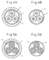
- Fig. 4A shows a first embodiment of the absorber 3 shown in Fig. 1, and Fig. 4B shows a variation of the absorber shown in Fig. 4A.
- the absorber 3 is formed by bundling three elements 6 for three phases (the wiring members each formed of the conductor 7 covered with the insulating material 8) shown in Fig. 2 together, applying the shield 11 around the bundled elements 6, and applying a sheath 12 over the shield 11.
- One end of the conductor 7 of each element 6 is connected to the input terminal of the corresponding phase, and the other end thereof is open or connected to one of the other elements through the member of the high-impedance.
- the shield 11 bundling the three elements 6 (for three phases) together may be exposed without applying the sheath 12 over the shield 11, as the absorber shown in Fig. 4B.
- Fig. 5A shows a second embodiment of the absorber 3 shown in Fig. 1
- Fig. 5B shows a variation of the absorber shown in Fig. 5A.
- the absorber 3 is formed by bundling three elements 6' for three phases (the wiring members each formed by covering the conductor 7 with the insulating material 8, applying the shield 9 around the insulating material 8, and applying the sheath 10 over the shield 9) shown in Fig. 3A together, applying a shield 11 around the bundled elements 6', and applying a sheath 12 over the shield 11.
- the shield 11 bundling the three elements 6' (for three phases) together may be exposed without applying the sheath 12 over the shield 11, as the absorber shown in Fig. 5B.
- a conductive material or a surge suppression material covered with plating is used as the conductor 7 of the elements 6, 6' making up the absorber 3, for promoting the attenuation of the high-frequency noise and increasing the resistance and the inductance.
- a material having a larger conductor resistance and a larger complex permeability than copper such as Ni (nickel) plating, is selected for a conductive material or a plating material.
- Ni (nickel) plating is selected for a conductive material or a plating material.
- As an insulating material of high dielectric constant and high dielectric loss on the other hand, vinylidene fluoride is used.
- the shield may be a commonly used braided one. Also, PVC or the like is used for the sheath.
- the element 6 or 6' of the absorber 3 is about four times as long as a cable having a standard length and extending between the inverter amplifier 2 and the electric motor 1. In the case where a machine in which the electric motor 1 is used is determined and a positional relation between the inverter amplifier 2 and the motor 1, and therefore the length of the cable extending therebetween, is determined, the absorber 3 including the elements 6, 6' about four times as long as the cable having the above length is built in the electric motor 1.
- the absorber 3 is degenerated after long use.
- terminals for detecting the voltage, the current change and the resistance of the conductor 7 of the elements 6, 6' making up the absorber 3 are provided on the absorber 3.
- the voltage, the current change and the resistance of the conductor 7 as well as the temperature of the electric motor 1 are measured through these terminals. Based on these measurements, the degree of the degeneration of the absorber may be monitored and managed.
- the surge voltage was measured for the electric motor 1 having the absorber 3 built therein according to the present invention on the one hand and the conventional electric motor not having the absorber 3 built therein on the other hand.
- the increase in the voltage under the effect of the surge voltage with respect to the voltage in the stable state free of the effect of the surge voltage was about 40 to 50 % less than the increase in the voltage of the conventional electric motor having no absorber 3 built therein.
- the surge voltage can be reduced by 40 to 50 %, and therefore the deterioration of the insulation of the electric motor can be suppressed depending on the reduced surge voltage.
Landscapes
- Engineering & Computer Science (AREA)
- Power Engineering (AREA)
- Microelectronics & Electronic Packaging (AREA)
- Physics & Mathematics (AREA)
- Electromagnetism (AREA)
- Control Of Ac Motors In General (AREA)
- Emergency Protection Circuit Devices (AREA)
- Motor Or Generator Frames (AREA)
Applications Claiming Priority (2)
| Application Number | Priority Date | Filing Date | Title |
|---|---|---|---|
| JP2003422809 | 2003-12-19 | ||
| JP2003422809A JP3920262B2 (ja) | 2003-12-19 | 2003-12-19 | 電動機 |
Publications (1)
| Publication Number | Publication Date |
|---|---|
| EP1544983A1 true EP1544983A1 (de) | 2005-06-22 |
Family
ID=34510693
Family Applications (1)
| Application Number | Title | Priority Date | Filing Date |
|---|---|---|---|
| EP04029841A Withdrawn EP1544983A1 (de) | 2003-12-19 | 2004-12-16 | Elektrischer Motor |
Country Status (4)
| Country | Link |
|---|---|
| US (1) | US20050135024A1 (de) |
| EP (1) | EP1544983A1 (de) |
| JP (1) | JP3920262B2 (de) |
| CN (1) | CN100386951C (de) |
Families Citing this family (5)
| Publication number | Priority date | Publication date | Assignee | Title |
|---|---|---|---|---|
| JP4461120B2 (ja) | 2006-06-26 | 2010-05-12 | 日立オートモティブシステムズ株式会社 | インバータ駆動回転機システム及びそれを用いる電動車両 |
| JP5155775B2 (ja) * | 2008-08-23 | 2013-03-06 | 公立大学法人首都大学東京 | モータ端子装置 |
| JP5272593B2 (ja) * | 2008-09-02 | 2013-08-28 | トヨタ自動車株式会社 | 電動機駆動システムおよびそれを備えた車両 |
| JP2012105493A (ja) * | 2010-11-12 | 2012-05-31 | Oki Electric Cable Co Ltd | 短尺対応サージ抑制ユニット |
| JP5850355B1 (ja) * | 2015-07-09 | 2016-02-03 | 株式会社オートネットワーク技術研究所 | ノイズフィルタ付き導電路 |
Citations (7)
| Publication number | Priority date | Publication date | Assignee | Title |
|---|---|---|---|---|
| US2690469A (en) * | 1952-01-05 | 1954-09-28 | Thomas A Perls | Flexible, low-noise, electrical cable |
| GB1514314A (en) * | 1974-07-12 | 1978-06-14 | Siemens Ag | Synchronous machines |
| US4687977A (en) * | 1984-10-22 | 1987-08-18 | General Electric Company | Electronically controlled motor and methods of operating same |
| US6011338A (en) * | 1998-07-10 | 2000-01-04 | Reliance Electric Industrial Company | Electric motor having auxiliary winding arrangement for electrostatic shielding |
| US6208057B1 (en) * | 1998-12-28 | 2001-03-27 | Visteon Global Technologies, Inc. | Electrical machine with reduced audible noise |
| US6304013B1 (en) * | 1999-06-30 | 2001-10-16 | General Electric Company | Line termination network assembly for an electric motor |
| JP2001307561A (ja) * | 2000-04-18 | 2001-11-02 | Daido Steel Co Ltd | シールドケーブル |
Family Cites Families (4)
| Publication number | Priority date | Publication date | Assignee | Title |
|---|---|---|---|---|
| JPS6096158A (ja) * | 1983-10-27 | 1985-05-29 | Toshiba Corp | 回転電機の騒音低減装置 |
| US6340013B1 (en) * | 1997-07-03 | 2002-01-22 | Richard Berkeley Britton | Four-stroke internal combustion engine with recuperator in cylinder head |
| GB9905247D0 (en) * | 1999-03-09 | 1999-04-28 | Johnson Electric Sa | Small electric motor |
| JP2004055185A (ja) * | 2002-07-17 | 2004-02-19 | Toshiba Aitekku Kk | エナメル線 |
-
2003
- 2003-12-19 JP JP2003422809A patent/JP3920262B2/ja not_active Expired - Fee Related
-
2004
- 2004-12-16 EP EP04029841A patent/EP1544983A1/de not_active Withdrawn
- 2004-12-17 US US11/013,452 patent/US20050135024A1/en not_active Abandoned
- 2004-12-17 CN CNB2004101013626A patent/CN100386951C/zh not_active Expired - Fee Related
Patent Citations (7)
| Publication number | Priority date | Publication date | Assignee | Title |
|---|---|---|---|---|
| US2690469A (en) * | 1952-01-05 | 1954-09-28 | Thomas A Perls | Flexible, low-noise, electrical cable |
| GB1514314A (en) * | 1974-07-12 | 1978-06-14 | Siemens Ag | Synchronous machines |
| US4687977A (en) * | 1984-10-22 | 1987-08-18 | General Electric Company | Electronically controlled motor and methods of operating same |
| US6011338A (en) * | 1998-07-10 | 2000-01-04 | Reliance Electric Industrial Company | Electric motor having auxiliary winding arrangement for electrostatic shielding |
| US6208057B1 (en) * | 1998-12-28 | 2001-03-27 | Visteon Global Technologies, Inc. | Electrical machine with reduced audible noise |
| US6304013B1 (en) * | 1999-06-30 | 2001-10-16 | General Electric Company | Line termination network assembly for an electric motor |
| JP2001307561A (ja) * | 2000-04-18 | 2001-11-02 | Daido Steel Co Ltd | シールドケーブル |
Non-Patent Citations (1)
| Title |
|---|
| PATENT ABSTRACTS OF JAPAN vol. 2002, no. 03 3 April 2002 (2002-04-03) * |
Also Published As
| Publication number | Publication date |
|---|---|
| JP3920262B2 (ja) | 2007-05-30 |
| JP2005185001A (ja) | 2005-07-07 |
| US20050135024A1 (en) | 2005-06-23 |
| CN1630168A (zh) | 2005-06-22 |
| CN100386951C (zh) | 2008-05-07 |
Similar Documents
| Publication | Publication Date | Title |
|---|---|---|
| US8174810B2 (en) | Method and apparatus for reducing differential mode and common mode reflections in motor drives | |
| US20140232505A1 (en) | Coil structure and electronic device | |
| US7060892B2 (en) | Method of transmitting electrical power | |
| JP2006508589A (ja) | パワーライン伝送のための誘導カップラの構成体 | |
| JP6032841B2 (ja) | サージ抑制システム、サージ抑制ケーブル、サージ抑制ユニット及びサージ抑制機能付きケーブル | |
| EP1544983A1 (de) | Elektrischer Motor | |
| CN100405508C (zh) | 三导线电缆 | |
| JP4093539B2 (ja) | サージ抑制型高速メタリックケーブル | |
| EP1193828B1 (de) | Stromerzeugungssystem mit Statorspulen zur Spannungsverteilung zwischen inneren Kühlrohren und Wicklungssträngen sowie dazugehörige Verfahren | |
| US12282051B2 (en) | Litz wire health monitoring | |
| JP6652691B1 (ja) | 電動機駆動装置 | |
| JP4131686B2 (ja) | 反射型サージ抑制ケーブル | |
| JP4417845B2 (ja) | 供給線構造 | |
| JP3601118B2 (ja) | 固定子巻線を有する電動機 | |
| JP4631585B2 (ja) | インバータシステム | |
| CN219457185U (zh) | 电源线、电连接设备和用电器 | |
| US4437083A (en) | Current transformer for turbine generators | |
| JP2873376B2 (ja) | 電 線 | |
| JP4656528B2 (ja) | インダクタンス素子 | |
| FI104394B (fi) | Yhdysjohdinrakenne taajuusmuuttajan ja sen kuorman välillä | |
| JP2007074811A (ja) | サージ抑制ユニット組み合せ体 | |
| SU936050A1 (ru) | Широкополосный трансформатор | |
| JP7044578B2 (ja) | 信号伝送路、信号伝送路の製造方法 | |
| JPH02184215A (ja) | 電力ケーブル線路 | |
| JP5201164B2 (ja) | インバータシステム |
Legal Events
| Date | Code | Title | Description |
|---|---|---|---|
| PUAI | Public reference made under article 153(3) epc to a published international application that has entered the european phase |
Free format text: ORIGINAL CODE: 0009012 |
|
| AK | Designated contracting states |
Kind code of ref document: A1 Designated state(s): AT BE BG CH CY CZ DE DK EE ES FI FR GB GR HU IE IS IT LI LT LU MC NL PL PT RO SE SI SK TR |
|
| AX | Request for extension of the european patent |
Extension state: AL BA HR LV MK YU |
|
| 17P | Request for examination filed |
Effective date: 20051114 |
|
| AKX | Designation fees paid |
Designated state(s): DE |
|
| 17Q | First examination report despatched |
Effective date: 20060914 |
|
| STAA | Information on the status of an ep patent application or granted ep patent |
Free format text: STATUS: THE APPLICATION IS DEEMED TO BE WITHDRAWN |
|
| 18D | Application deemed to be withdrawn |
Effective date: 20090526 |