EP1544872A2 - Système magnétique supraconducteur avec pompe de flux travaillant en continu et procédés de fonctionnement correspondant - Google Patents
Système magnétique supraconducteur avec pompe de flux travaillant en continu et procédés de fonctionnement correspondant Download PDFInfo
- Publication number
- EP1544872A2 EP1544872A2 EP04028362A EP04028362A EP1544872A2 EP 1544872 A2 EP1544872 A2 EP 1544872A2 EP 04028362 A EP04028362 A EP 04028362A EP 04028362 A EP04028362 A EP 04028362A EP 1544872 A2 EP1544872 A2 EP 1544872A2
- Authority
- EP
- European Patent Office
- Prior art keywords
- superconducting
- switch
- coil
- current
- secondary coil
- Prior art date
- Legal status (The legal status is an assumption and is not a legal conclusion. Google has not performed a legal analysis and makes no representation as to the accuracy of the status listed.)
- Granted
Links
Images


Classifications
-
- H—ELECTRICITY
- H01—ELECTRIC ELEMENTS
- H01F—MAGNETS; INDUCTANCES; TRANSFORMERS; SELECTION OF MATERIALS FOR THEIR MAGNETIC PROPERTIES
- H01F6/00—Superconducting magnets; Superconducting coils
- H01F6/006—Supplying energising or de-energising current; Flux pumps
- H01F6/008—Electric circuit arrangements for energising superconductive electromagnets
Definitions
- the invention relates to a magnet arrangement with a superconducting Magnetic coil system, which in the operating state an ohmic resistance greater than or equal to zero, and with a flow pump, which at least a superconductive switch and at least two superconducting Secondary coils includes.
- the superconducting magnet coil system includes one or more in series switched magnetic coils, which form a closed superconducting circuit form.
- the superconducting magnet coil system is typically in one Cryostats arranged. It can be ohmic in the operating state Resistance greater than zero, if the superconductors used until just under are under the critical load or if they are not sharp Transition from superconducting to normal conducting.
- the principle of a Flow pump is made by inductive coupling of energy resistive To compensate for losses of the solenoid or to load the coil or to discharged without large currents must be performed in the cryostat.
- the invention particularly relates to superconducting magnet coil systems a flow pump, which at least one superconducting switch and comprises at least two superconducting secondary coils, in which inductively a tension can be built up. So that tension to compensate Resisitiver losses or to charge or discharge in the superconducting Magnetic coil system can be fed, the secondary coils Superconducting to be connected in series with the magnetic coil system, which for example, by closing a superconducting switch.
- a magnet arrangement with a flow pump which is at least two Superconducting secondary coils is known from T.P. Bernat et. al., Rev. Sci. Instrum., Vol. 46, No 5, May 1975, and from L.J.M. van de Klundert et. al. Cryogenics, May 1981.
- This flow pump is based on the superconducting Magnetic coil system is bridged with two current paths, which one each Switch and a superconducting secondary coil include.
- their inductive coupling with the secondary coils opposite each other is large, power is cyclically switched on and off again. If in the same bar the superconducting switches connected in series with the secondary coils alternately opened and closed, arises over the Magnetic coil system a constant over the cycle voltage, apart from voltage spikes when opening the switch.
- the typical application of flow pumps is the loading and unloading of superconducting magnet coil systems.
- the advantage over the direct Feeding the operating current into the coils is that the currents to operate the river pump are much weaker than the typical ones Magnetic currents.
- the power supply lines can be made smaller and the Heat input in the cryostat can be reduced.
- the field of application of superconducting magnets also includes Fields of application in which the solenoid coils over the charging process Stay on the field for years and have the lowest possible field drift should.
- These include in particular superconducting magnet coil systems for Magnetic resonance methods.
- a Flow pump less for charging the magnet system of interest, but for Stabilization of the magnetic field in the operating state.
- An efficient flow pump would bring various advantages in this regard. It could for example Magnets with partial coils are built from high-temperature superconductors, which According to the current state of the art, the drift specifications for Do not meet magnetic resonance applications without additional measures. This would be the construction of magnets with stronger than the usual fields today enable. Further, by using a flow pump for Field stabilization the superconductors in the magnet are charged higher, which the Construction of more compact and less expensive magnets would allow.
- Object of the present invention is a flow pump according to the prior the technique to improve so that in addition to the loading and unloading of a superconducting magnet coil system also good stabilization of the Magnetic field of the magnetic coil system in the operating state for a long time is possible, especially when the magnetic coil system is easily resists and the field stability requirements are very high.
- the improved Flow pump assembly allows an operating method, with which an over all cycles of the flow pump constant voltage across the solenoid system can be created.
- This object is achieved in a magnet arrangement of the initially solved type solved by at least one superconducting current path is present, in which the superconducting magnet coil system or parts thereof connected in series with at least two secondary coils and in which at least one secondary coil by closing a Superconducting switch superconducting can be bridged, and that at least two primary coils are present, which are independent of each other can be fed with one power and each with at least one of the secondary coils are inductively coupled.
- the invention provides that a superconducting current path is present, in which the superconducting magnet coil system or parts thereof connected in series with at least two secondary coils and in which at least one secondary coil by closing a Superconducting switch can be bridged.
- the secondary coils, each with its own primary coil are inductively coupled.
- This arrangement enables an operation method of the flow pump in which in a first step, a first primary coil, which with a first, not coupled superconducting bridged secondary coil is charged until in the Primary coil a maximum final current is reached.
- This can be a tension be built over the superconducting magnet coil system, which for example, exactly the resistive voltage to be compensated in the Magnetic coil system corresponds.
- the first Primary coil are discharged back to their initial current.
- this Phase is over a second, previously with a closed switch superconducting bridged secondary coil of the superconducting switch opened and in that primary coil which inductively couples to this secondary coil, the Power up, which induces a voltage in this secondary coil becomes.
- the current ramp in the second primary coil is chosen so that through the in the second secondary coil induced voltage both through the Discharging the first primary coil induced in the first secondary coil Voltage as well as the resisitve voltage across the superconducting Magnetic coil system is compensated.
- the switch over the second Secondary coil closed again and the second primary coil - at closed switch - moved back to its initial current. The cycle can now start over.
- the advantage of an arrangement according to the invention is therefore that thanks to several independently supplied primary coils in different Secondary coils different voltages can be induced, which thanks to the series connection of these secondary coils to a total voltage be added.
- the series connection of the secondary coils with the superconducting Magnetic coil system allows the supply of this total voltage in the superconducting magnet coil system.
- the great flexibility of the arrangement allows that through appropriate process steps in each phase of the Flow pump cycle a desired voltage across the superconducting Magnetic coil system can be maintained.
- an embodiment of the invention is preferred Arrangement in which a superconducting switch, a secondary coil bridged together with a resistor, which with this secondary coil is connected in series, the resistor having a value, measured in ohms, between 0 and the value of the inductance of this secondary coil, measured in Henry, has.
- the advantage of this arrangement is that when loading and Discharging a primary coil which is inductively coupled to this secondary coil is not uncontrollably high when the superconducting switch is closed Currents in the secondary coil can be induced.
- a particularly preferred embodiment of the invention Arrangement is characterized by the fact that instead of the above Embodiment used resistor another superconducting switch is used.
- This embodiment thus provides that a superconducting Switch a secondary coil together with another superconducting one Switch bridged, which with the said secondary coil in series is switched; See also Figure 3.
- This can be done by appropriate loading and unloading the associated primary coil and by opening and closing the other switch the power in the secondary coil control.
- This can be prevented so that before opening the first Switch at a certain point of the pumping cycle, a current over this Switch flows. This causes voltage pulses above the superconducting Magnetic coil system prevents, especially in sensitive Applications such as nuclear magnetic resonance method is inevitable.
- Embodiments of the invention are also particularly advantageous Arrangement in which primary or secondary coils of the superconducting Magnetic coil system inductively largely decoupled or in Working volume of the superconducting magnet coil system essentially no Create field. Thus, disturbances of the magnetic field in the working volume prevented during operation of the flow pump.
- a further advantageous embodiment of the arrangement according to the invention is characterized by the fact that at least one primary coil is superconducting.
- a current flowing in a superconducting primary coil generates to normal conducting primary coils no heat. If the primary coils are in the Cryostats are located, so the coolant losses can be reduced.
- At least one of superconducting switch can be actuated by a heater whose supply lines at least partially superconducting.
- An advantageous embodiment of the arrangement according to the invention is characterized characterized by having at least a portion of the superconducting Magnet coil system is superconducting or bridged with a resistor.
- This arrangement can be used to reduce the impact of small Voltage fluctuations, such as when opening switches of the flow pump on to dampen the entire field of the superconducting magnet system. So that Damping is effective, the resistance (in ohms) may be the order of magnitude Do not exceed inductance (in Henry) of the bridged section.
- the arrangement according to the invention is particularly advantageous when it is part a magnetic resonance magnetic resonance apparatus.
- Magnetic arrangements are connected to an apparatus for active field stabilization, as which the flow pump according to the invention in this field of application is preferably used, particularly high requirements in terms of constancy the stabilization voltage and minimize the heat input in the Cryostats asked. Exactly these criteria are listed in the above Embodiments of the flow pump according to the invention better fulfilled than with River pumps according to the prior art.
- An advantageous embodiment of the inventive arrangement comprises a superconducting magnet coil system in which one or more coils are wound with high temperature superconductors.
- the potentially higher drift at Use of high temperature superconductors can be with the compensate flow pump according to the invention, while maintaining the Field stability of the superconducting magnet coil system.
- a first method is characterized by a particularly simple Cycle of loading and unloading of the primary reels and opening and closing of the reels Switch off.
- this method for operating a device with at least a first and a second superconducting secondary coil and a first superconducting switch becomes the first superconducting switch, which bypasses the second secondary coil, periodically opened and closed.
- the first switch When the first switch is closed, the current in a first Primary coil, which inductively couples with the first secondary coil of a Initial value driven to a final value.
- the first switch is open the current in this primary coil again largely to the initial value reset.
- the current is switched on a second primary coil which couples with the second secondary coil of moved to an initial value to a final value and closed first Switch again largely reset to the initial value.
- An improved method using the further, second superconducting switch is characterized in that when closed first switch a second superconducting switch, which with the second Secondary coil is connected in series and together with this from the first superconducting switch is bridged, at least temporarily opened.
- a second superconducting switch which with the second Secondary coil is connected in series and together with this from the first superconducting switch is bridged, at least temporarily opened.
- This process variant can be further improved by setting the current in this coil to an amount of I * L / K before reaching the final current of zero amperes in the second primary coil and that the second superconducting switch is opened at the latest after reaching this current, and that then, while resetting the current in the second primary coil to the final current of zero amperes and until the first opening of the first superconducting switch, the second superconducting switch remains superconducting closed, the current in the superconducting magnet coil system, L the self-inductance of the second secondary coil and K denoting the inductive coupling in Henry between the second secondary coil and the second primary coil.
- This process is described in more detail in the example below. Its particular advantage is that no current flows over it before opening the first superconducting switch. Thus, voltage peaks are prevented over the superconducting magnet coil system, which is an important criterion for the use of the flow pump according to the invention for field stabilization in sensitive applications.
- the steps of cyclic repeated to the superconducting Magnetic coil system either to charge or discharge, or to the power to stabilize accurately in the magnet coil system to an operating value.
- the inventive arrangement also allows the application of a respect Reduction of heat input in the cryostat particularly advantageous Process variant in which that phase of the pumping cycle, during which no superconducting switch is open, lasts longer than the phases with open, so heated, superconducting switches. In contrast, must in flow pumps according to the prior art permanently heated switch become.
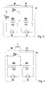
- FIG. 1 An arrangement according to the invention is shown schematically with reference to FIG. 1 , which comprises a superconducting magnet coil system M and a flow pump P.
- the magnet coil system M may have a resistance of the size R.
- two further superconducting coils M1 and M2 are connected in series, which serve as secondary coils in the flow pump P. In these coils can be induced by changing the current I1 or I2 in the primary coils C1 and C2 of the flow pump P by inductive coupling a voltage.
- One of the secondary coils, namely M2 is bridged by a superconductive switch S1 .
- FIG. 2 shows schematically an arrangement according to the invention, in which the secondary coil M2, which is bridged with the superconducting switch S1 , is connected in series with a resistor R2 , such that the switch S1 bridges both the coil M2 and the resistor R2 .
- FIG. 3 shows an arrangement according to the invention as in FIG. 2, with the difference that a second superconductive switch S2 is used instead of the resistor R2 .
- Figure 4 shows an inventive arrangement as in Figure 1, in which in addition a portion of the superconducting magnet coil system M is bridged with a resistor r .
- FIG. 5 shows, for an operating method of the inventive flow pump according to FIG. 3, the currents I1 and I2 in the primary coils C1 and C2 of the flow pump P and the switching states of the superconducting switches S1 and S2 , the current IS1 in the switch S1 and that through the flow pump P above the latter superconducting magnet coil system M built-up voltage VMagnet.
- time t is plotted. The method is optimized to keep the voltage VMagnet constant over any number of pump cycles and to produce no voltage spikes. In addition, the duration during which the superconductive switches are opened is minimized.
- the two switches S1 and S2 are superconductingly closed and the operating current IM of the superconducting magnet coil system M flows via the current path M-M1-. M2-S2.
- the current I2 in the second primary coil C2 is zero and the current I1 in the first primary coil C1 is treated with a continuous ramp of 0.25 A / s during 8s of - loaded 1A + 1A. As a result, a voltage of 25 ⁇ V is induced in the secondary coil M1 .
- the voltage induced in M1 is -100 ⁇ V in this phase .
- the switch S1 is opened and the current in the second primary coil C2 is driven from zero to 2.5A. As a result, a voltage of 125 ⁇ V is induced in the second secondary coil M2 .
- the system is not yet back to its initial state because the current I2 in the second primary coil C2 is not zero.
- I2 When resetting I2 to zero, it must also be ensured that the operating current IM at the end again flows through the secondary coil M2 and not via the closed switch S1 , that is, IS1 should be zero. If this condition is not met, the renewed opening of the switch S1 in the following cycle of the flow pump P generates an undesired voltage pulse across the superconducting magnet coil system M.
- the goal of bringing both I2 and IS1 to zero is achieved by driving I2 to the value - IM * KM2C2 / LM2 between t2 and t3 , in example -1A.
- the switch S2 is opened, whereby the current in M2 is kept at zero.
- the switch S2 is closed again and then, until time t4, the current I2 in the second primary coil C2 is reduced to zero.
- the advantages of this arrangement become clear.
- the voltage over the entire cycle of the flow pump P can be kept constant and there are no voltage spikes when opening superconducting switches.
- the switches are open only during a fraction of the operating cycle of the flow pump P , whereby the heat input in the cryostat through the switches is minimal.
- the requirements for the temporal stability of the magnetic field are particularly high.
- the overall resistivity of the magnet coil system may be at most on the order of 0.1 * 10 -9 ohms for field drift to be acceptable.
- the resistivity of the magnet coil system may therefore be over a thousand times greater than in an arrangement without the inventive flow pump.
- a magnet arrangement according to the invention comprises a superconducting magnet coil system M and at least two superconducting secondary coils M1, M2, which are connected in series with the magnet coil system, and a first superconducting switch S1 , which can superconductingly bridge the second of the secondary coils M2 .
- the magnet arrangement has a second superconducting switch S2 , which is connected in series with the second secondary coil M2 , wherein the first superconducting switch S1 can bridge the entirety of the second secondary coil M2 and the second superconducting switch S2 .
- inductive coupling can be generated by means of at least two independent primary coils C1 , C2 a predetermined voltage in each of the secondary coils M1, M2 , regardless of the other secondary coil.
- the system of secondary coils, primary coils and superconducting switches forms a flux pump P for the magnet coil system. This flux pump can be used well to stabilize the magnetic field of the magnetic coil system in the operating state for a long time, that is, for drift compensation in the magnetic coil system.
Landscapes
- Physics & Mathematics (AREA)
- Electromagnetism (AREA)
- Engineering & Computer Science (AREA)
- Power Engineering (AREA)
- Magnetic Resonance Imaging Apparatus (AREA)
Applications Claiming Priority (2)
| Application Number | Priority Date | Filing Date | Title |
|---|---|---|---|
| DE10358549 | 2003-12-15 | ||
| DE10358549A DE10358549B4 (de) | 2003-12-15 | 2003-12-15 | Supraleitendes Magnetsystem mit kontinuierlich arbeitender Flusspumpe und zugehörige Betriebsverfahren |
Publications (3)
| Publication Number | Publication Date |
|---|---|
| EP1544872A2 true EP1544872A2 (fr) | 2005-06-22 |
| EP1544872A3 EP1544872A3 (fr) | 2008-06-11 |
| EP1544872B1 EP1544872B1 (fr) | 2010-04-28 |
Family
ID=34485376
Family Applications (1)
| Application Number | Title | Priority Date | Filing Date |
|---|---|---|---|
| EP04028362A Expired - Lifetime EP1544872B1 (fr) | 2003-12-15 | 2004-11-30 | Système magnétique supraconducteur avec pompe de flux travaillant en continu et procédés de fonctionnement correspondant |
Country Status (4)
| Country | Link |
|---|---|
| US (1) | US6946936B2 (fr) |
| EP (1) | EP1544872B1 (fr) |
| JP (1) | JP4713880B2 (fr) |
| DE (2) | DE10358549B4 (fr) |
Families Citing this family (15)
| Publication number | Priority date | Publication date | Assignee | Title |
|---|---|---|---|---|
| US7064550B2 (en) * | 2004-11-16 | 2006-06-20 | General Electric Company | Method and apparatus for field drift compensation of a superconducting magnet |
| US7533068B2 (en) | 2004-12-23 | 2009-05-12 | D-Wave Systems, Inc. | Analog processor comprising quantum devices |
| DE102005020690B4 (de) * | 2005-05-03 | 2007-08-30 | Bruker Biospin Ag | Magnetanordnung mit Vorrichtung zum Dämpfen von Spannungsspitzen einer Speisung |
| DE102007006324B4 (de) * | 2007-02-08 | 2011-04-28 | Bruker Biospin Ag | Magnetspulensystem mit aktiver Driftkompensation für zwei unabhängige Strompfade |
| JP2010524064A (ja) | 2007-04-05 | 2010-07-15 | ディー−ウェイブ システムズ,インコーポレイテッド | 汎用断熱量子コンピュータの物理的実現 |
| US8107211B2 (en) * | 2007-08-29 | 2012-01-31 | Advanced Magnet Lab, Inc. | High temperature superconducting electromechanical system with frequency controlled commutation for rotor excitation |
| WO2011074092A1 (fr) * | 2009-12-17 | 2011-06-23 | 株式会社日立製作所 | Dispositif d'aimant supraconducteur et procédé d'application de courant électrique à un aimant supraconducteur |
| US8738105B2 (en) * | 2010-01-15 | 2014-05-27 | D-Wave Systems Inc. | Systems and methods for superconducting integrated circuts |
| US9810755B2 (en) | 2013-12-16 | 2017-11-07 | General Electric Company | System and method for energizing a superconducting magnet |
| US10002107B2 (en) | 2014-03-12 | 2018-06-19 | D-Wave Systems Inc. | Systems and methods for removing unwanted interactions in quantum devices |
| CN111788588B (zh) | 2017-12-20 | 2024-08-02 | D-波系统公司 | 量子处理器中耦合量子位的系统和方法 |
| US12536459B2 (en) | 2020-06-30 | 2026-01-27 | D-Wave Systems Inc. | Systems and methods for coupling between qubits |
| WO2022115278A1 (fr) | 2020-11-24 | 2022-06-02 | D-Wave Systems Inc. | Systèmes, articles et procédés pour un condensateur accordable |
| CN113628828B (zh) * | 2021-08-23 | 2022-07-22 | 上海交通大学 | 高温超导磁通泵及其铁芯绕组电流波形控制方法 |
| CN118888246B (zh) * | 2024-07-10 | 2025-09-12 | 华中科技大学 | 一种基于全波变压器整流器的超导磁体励磁装置 |
Family Cites Families (15)
| Publication number | Priority date | Publication date | Assignee | Title |
|---|---|---|---|---|
| US3244943A (en) * | 1961-11-29 | 1966-04-05 | California Inst Res Found | Continuous magnetic-flux pump |
| US3277322A (en) * | 1963-04-01 | 1966-10-04 | North American Aviation Inc | Method and apparatus for magnetic flux accumulation and current generation |
| GB1068372A (en) * | 1963-05-29 | 1967-05-10 | Gen Electric | Electric current pumping arrangement |
| FR1522300A (fr) * | 1967-02-23 | 1968-04-26 | Commissariat Energie Atomique | Procédé pour l'introduction d'un courant dans un circuit supraconducteur et dispositif pour la mise en oeuvre de ce procédé |
| US3568002A (en) * | 1968-11-18 | 1971-03-02 | Atomic Energy Commission | Multiaction flux pump |
| US3848162A (en) * | 1972-07-11 | 1974-11-12 | President Of The Agency Of Ind | Method and apparatus for charging a superconductive coil |
| JPS5146589B2 (fr) * | 1972-07-11 | 1976-12-09 | ||
| JPS50154092A (fr) * | 1974-05-31 | 1975-12-11 | ||
| US4096403A (en) * | 1976-06-28 | 1978-06-20 | Electric Power Research Institute, Inc. | Superconducting hybrid magnetic flux pump |
| JPS5345998A (en) * | 1976-10-07 | 1978-04-25 | Japan National Railway | Flux pump for exiting superconductive magnet |
| NL8501762A (nl) * | 1985-06-19 | 1987-01-16 | Holec Syst & Componenten | Supergeleidende gelijkrichter voor het omzetten van een relatief lage wisselstroom in een relatief hoge gelijkstroom. |
| FR2592736B1 (fr) * | 1986-01-06 | 1988-03-04 | Alsthom | Chargeur de bobine supraconductrice |
| US5965959A (en) * | 1996-07-02 | 1999-10-12 | American Superconductor Corporation | Superconducting magnets and power supplies for superconducting devices |
| DE19920443A1 (de) * | 1999-05-04 | 2000-11-09 | Abb Research Ltd | Anordnung zur Strombegrenzung mit einem supraleitenden Transformator |
| DE10065420C2 (de) * | 2000-12-27 | 2003-08-07 | Siemens Ag | Flusspumpe mit Hochtemperatursupraleiter und damit zu betreibender supraleitender Elektromagnet |
-
2003
- 2003-12-15 DE DE10358549A patent/DE10358549B4/de not_active Expired - Fee Related
-
2004
- 2004-11-30 DE DE502004011096T patent/DE502004011096D1/de not_active Expired - Lifetime
- 2004-11-30 EP EP04028362A patent/EP1544872B1/fr not_active Expired - Lifetime
- 2004-12-13 US US11/008,949 patent/US6946936B2/en not_active Expired - Lifetime
- 2004-12-15 JP JP2004363501A patent/JP4713880B2/ja not_active Expired - Lifetime
Non-Patent Citations (4)
| Title |
|---|
| BERNAT T P ET AL: "Automated flux pump for energizing high current superconducting loads" REVIEW OF SCIENTIFIC INSTRUMENTS, AIP, MELVILLE, NY, US, Bd. 45, Nr. 5, 1. Mai 1975 (1975-05-01), Seiten 582-585, XP007904624 ISSN: 0034-6748 * |
| LEV M BARKOV ET AL: "Superconducting Rectifier Fluxpump for Magnet System of the CMD-2 Detector" IEEE TRANSACTIONS ON APPLIED SUPERCONDUCTIVITY, IEEE SERVICE CENTER, LOS ALAMITOS, CA, US, Bd. 9, Nr. 3, 1. September 1999 (1999-09-01), XP011083030 ISSN: 1051-8223 * |
| VAN DE KLUNDERT L J M ET AL: "Fully superconducting rectifiers and fluxpumps Part 1: Realized methods for pumping flux" CRYOGENICS, ELSEVIER, KIDLINGTON, GB, 1. April 1981 (1981-04-01), Seiten 195-206, XP007904623 ISSN: 0011-2275 * |
| VAN DE KLUNDERT L J M ET AL: "On fully superconducting rectifiers and fluxpumps. A review. Part 2: Commutation modes, characteristics and switches" CRYOGENICS, ELSEVIER, KIDLINGTON, GB, 1. Mai 1981 (1981-05-01), Seiten 267-277, XP007904625 ISSN: 0011-2275 * |
Also Published As
| Publication number | Publication date |
|---|---|
| DE10358549B4 (de) | 2005-11-24 |
| DE502004011096D1 (de) | 2010-06-10 |
| DE10358549A1 (de) | 2005-07-14 |
| US6946936B2 (en) | 2005-09-20 |
| EP1544872A3 (fr) | 2008-06-11 |
| JP4713880B2 (ja) | 2011-06-29 |
| EP1544872B1 (fr) | 2010-04-28 |
| US20050127915A1 (en) | 2005-06-16 |
| JP2005183971A (ja) | 2005-07-07 |
Similar Documents
| Publication | Publication Date | Title |
|---|---|---|
| EP1544872B1 (fr) | Système magnétique supraconducteur avec pompe de flux travaillant en continu et procédés de fonctionnement correspondant | |
| DE69533962T2 (de) | Gleichstromwandler und denselben verwendende steuereinrichtung für induktive last | |
| DE69803521T2 (de) | Verfahren und apparat zur unterdrückung reflektierter energie aufgrund von stufenfehlanpassung in einem nichtlinearen magnetischen kompressionsmodul | |
| EP0704097B1 (fr) | Procede et dispositif de commande de consommateurs electromagnetiques | |
| DE60011038T2 (de) | Zeit und Fall-kontrolliertes Aktivierungssystem für die Aufladung und die Entladung von piezoelektrischen Elementen | |
| EP0871230B1 (fr) | Procédé et appareil pour charger et décharger un élément piézoélectrique | |
| DE112007000098T5 (de) | Supraleitender Schnellschalter | |
| WO1987005075A1 (fr) | Procede et circuit d'excitation de consommateurs electromagnetiques | |
| DE19539071A1 (de) | Vorrichtung zur Ansteuerung wenigstens eines elektromagnetischen Verbrauchers | |
| DE1614970A1 (de) | Gradienten-Loeschspulen-Anordnung | |
| DE3323400C2 (de) | Stromversorgungsschaltung für eine elektromagnetische Betätigungsvorrichtung | |
| DE2639944C3 (de) | Gleichspannungswandler | |
| DE3415041C2 (de) | Stromversorgungsschaltung für eine Spule | |
| DE19731690C2 (de) | Leistungsverstärker und Kernspintomograph | |
| DE19704089A1 (de) | Verfahren zur Steuerung eines Zerhacker(Chopper)-Treibers und Schaltungsanordnung zur Durchführung des Verfahrens | |
| EP3667351B1 (fr) | Procédé de charge d'un dispositif de shim-hts | |
| DE60120900T2 (de) | Schaltkreis und verfahren zur hocheffizienten ansteuerung von piezoelektrischen lasten | |
| DE4019008C2 (de) | Supraleitende Magnetvorrichtung | |
| DE4021524A1 (de) | Supraleitende spulenanordnung und verfahren zum betreiben derselben | |
| EP1638196A2 (fr) | Dispositif pour alimenter des charges variables | |
| EP3889633B1 (fr) | Dispositif de shim doté d'une ligne supraconductrice à haute température, agencement magnétique et procédé de charge d'un dispositif de shim hts | |
| EP1087512A2 (fr) | Convertisseur multi-points du type ARCP avec condensateurs intermédiaires à tension variable | |
| DE19734045C2 (de) | Leistungsverstärker und Kernspintomograph | |
| EP0740407B1 (fr) | Dispositif de freinage pour un moteur série à commutateur | |
| EP1720179B1 (fr) | Ensemble magnétique ayant un dispositif pour reduire les pics de tension d'un alimentation et methode d'operation d'un tel ensemble |
Legal Events
| Date | Code | Title | Description |
|---|---|---|---|
| PUAI | Public reference made under article 153(3) epc to a published international application that has entered the european phase |
Free format text: ORIGINAL CODE: 0009012 |
|
| AK | Designated contracting states |
Kind code of ref document: A2 Designated state(s): AT BE BG CH CY CZ DE DK EE ES FI FR GB GR HU IE IS IT LI LU MC NL PL PT RO SE SI SK TR |
|
| AX | Request for extension of the european patent |
Extension state: AL HR LT LV MK YU |
|
| PUAL | Search report despatched |
Free format text: ORIGINAL CODE: 0009013 |
|
| AK | Designated contracting states |
Kind code of ref document: A3 Designated state(s): AT BE BG CH CY CZ DE DK EE ES FI FR GB GR HU IE IS IT LI LU MC NL PL PT RO SE SI SK TR |
|
| AX | Request for extension of the european patent |
Extension state: AL HR LT LV MK YU |
|
| 17P | Request for examination filed |
Effective date: 20080628 |
|
| AKX | Designation fees paid |
Designated state(s): CH DE FR GB LI |
|
| GRAP | Despatch of communication of intention to grant a patent |
Free format text: ORIGINAL CODE: EPIDOSNIGR1 |
|
| GRAS | Grant fee paid |
Free format text: ORIGINAL CODE: EPIDOSNIGR3 |
|
| GRAA | (expected) grant |
Free format text: ORIGINAL CODE: 0009210 |
|
| AK | Designated contracting states |
Kind code of ref document: B1 Designated state(s): CH DE FR GB LI |
|
| REG | Reference to a national code |
Ref country code: GB Ref legal event code: FG4D Free format text: NOT ENGLISH |
|
| REG | Reference to a national code |
Ref country code: CH Ref legal event code: EP |
|
| REF | Corresponds to: |
Ref document number: 502004011096 Country of ref document: DE Date of ref document: 20100610 Kind code of ref document: P |
|
| PLBE | No opposition filed within time limit |
Free format text: ORIGINAL CODE: 0009261 |
|
| STAA | Information on the status of an ep patent application or granted ep patent |
Free format text: STATUS: NO OPPOSITION FILED WITHIN TIME LIMIT |
|
| 26N | No opposition filed |
Effective date: 20110131 |
|
| REG | Reference to a national code |
Ref country code: FR Ref legal event code: PLFP Year of fee payment: 12 |
|
| REG | Reference to a national code |
Ref country code: FR Ref legal event code: PLFP Year of fee payment: 13 |
|
| REG | Reference to a national code |
Ref country code: FR Ref legal event code: PLFP Year of fee payment: 14 |
|
| REG | Reference to a national code |
Ref country code: DE Ref legal event code: R082 Ref document number: 502004011096 Country of ref document: DE Representative=s name: KOHLER SCHMID MOEBUS PATENTANWAELTE PARTNERSCH, DE Ref country code: DE Ref legal event code: R081 Ref document number: 502004011096 Country of ref document: DE Owner name: BRUKER SWITZERLAND AG, CH Free format text: FORMER OWNER: BRUKER BIOSPIN AG, FAELLANDEN, CH |
|
| REG | Reference to a national code |
Ref country code: CH Ref legal event code: PFA Owner name: BRUKER SWITZERLAND AG, CH Free format text: FORMER OWNER: BRUKER BIOSPIN AG, CH |
|
| PGFP | Annual fee paid to national office [announced via postgrant information from national office to epo] |
Ref country code: GB Payment date: 20231123 Year of fee payment: 20 |
|
| P01 | Opt-out of the competence of the unified patent court (upc) registered |
Effective date: 20231220 |
|
| PGFP | Annual fee paid to national office [announced via postgrant information from national office to epo] |
Ref country code: FR Payment date: 20231124 Year of fee payment: 20 Ref country code: DE Payment date: 20231120 Year of fee payment: 20 Ref country code: CH Payment date: 20231202 Year of fee payment: 20 |
|
| REG | Reference to a national code |
Ref country code: DE Ref legal event code: R071 Ref document number: 502004011096 Country of ref document: DE |
|
| REG | Reference to a national code |
Ref country code: CH Ref legal event code: PL |
|
| REG | Reference to a national code |
Ref country code: GB Ref legal event code: PE20 Expiry date: 20241129 |
|
| PG25 | Lapsed in a contracting state [announced via postgrant information from national office to epo] |
Ref country code: GB Free format text: LAPSE BECAUSE OF EXPIRATION OF PROTECTION Effective date: 20241129 |
|
| PG25 | Lapsed in a contracting state [announced via postgrant information from national office to epo] |
Ref country code: GB Free format text: LAPSE BECAUSE OF EXPIRATION OF PROTECTION Effective date: 20241129 |