EP1544872A2 - Superconducting magnet system with continuously working flux pump and and related methods of operation - Google Patents
Superconducting magnet system with continuously working flux pump and and related methods of operation Download PDFInfo
- Publication number
- EP1544872A2 EP1544872A2 EP04028362A EP04028362A EP1544872A2 EP 1544872 A2 EP1544872 A2 EP 1544872A2 EP 04028362 A EP04028362 A EP 04028362A EP 04028362 A EP04028362 A EP 04028362A EP 1544872 A2 EP1544872 A2 EP 1544872A2
- Authority
- EP
- European Patent Office
- Prior art keywords
- superconducting
- switch
- coil
- current
- secondary coil
- Prior art date
- Legal status (The legal status is an assumption and is not a legal conclusion. Google has not performed a legal analysis and makes no representation as to the accuracy of the status listed.)
- Granted
Links
Images


Classifications
-
- H—ELECTRICITY
- H01—ELECTRIC ELEMENTS
- H01F—MAGNETS; INDUCTANCES; TRANSFORMERS; SELECTION OF MATERIALS FOR THEIR MAGNETIC PROPERTIES
- H01F6/00—Superconducting magnets; Superconducting coils
- H01F6/006—Supplying energising or de-energising current; Flux pumps
- H01F6/008—Electric circuit arrangements for energising superconductive electromagnets
Definitions
- the invention relates to a magnet arrangement with a superconducting Magnetic coil system, which in the operating state an ohmic resistance greater than or equal to zero, and with a flow pump, which at least a superconductive switch and at least two superconducting Secondary coils includes.
- the superconducting magnet coil system includes one or more in series switched magnetic coils, which form a closed superconducting circuit form.
- the superconducting magnet coil system is typically in one Cryostats arranged. It can be ohmic in the operating state Resistance greater than zero, if the superconductors used until just under are under the critical load or if they are not sharp Transition from superconducting to normal conducting.
- the principle of a Flow pump is made by inductive coupling of energy resistive To compensate for losses of the solenoid or to load the coil or to discharged without large currents must be performed in the cryostat.
- the invention particularly relates to superconducting magnet coil systems a flow pump, which at least one superconducting switch and comprises at least two superconducting secondary coils, in which inductively a tension can be built up. So that tension to compensate Resisitiver losses or to charge or discharge in the superconducting Magnetic coil system can be fed, the secondary coils Superconducting to be connected in series with the magnetic coil system, which for example, by closing a superconducting switch.
- a magnet arrangement with a flow pump which is at least two Superconducting secondary coils is known from T.P. Bernat et. al., Rev. Sci. Instrum., Vol. 46, No 5, May 1975, and from L.J.M. van de Klundert et. al. Cryogenics, May 1981.
- This flow pump is based on the superconducting Magnetic coil system is bridged with two current paths, which one each Switch and a superconducting secondary coil include.
- their inductive coupling with the secondary coils opposite each other is large, power is cyclically switched on and off again. If in the same bar the superconducting switches connected in series with the secondary coils alternately opened and closed, arises over the Magnetic coil system a constant over the cycle voltage, apart from voltage spikes when opening the switch.
- the typical application of flow pumps is the loading and unloading of superconducting magnet coil systems.
- the advantage over the direct Feeding the operating current into the coils is that the currents to operate the river pump are much weaker than the typical ones Magnetic currents.
- the power supply lines can be made smaller and the Heat input in the cryostat can be reduced.
- the field of application of superconducting magnets also includes Fields of application in which the solenoid coils over the charging process Stay on the field for years and have the lowest possible field drift should.
- These include in particular superconducting magnet coil systems for Magnetic resonance methods.
- a Flow pump less for charging the magnet system of interest, but for Stabilization of the magnetic field in the operating state.
- An efficient flow pump would bring various advantages in this regard. It could for example Magnets with partial coils are built from high-temperature superconductors, which According to the current state of the art, the drift specifications for Do not meet magnetic resonance applications without additional measures. This would be the construction of magnets with stronger than the usual fields today enable. Further, by using a flow pump for Field stabilization the superconductors in the magnet are charged higher, which the Construction of more compact and less expensive magnets would allow.
- Object of the present invention is a flow pump according to the prior the technique to improve so that in addition to the loading and unloading of a superconducting magnet coil system also good stabilization of the Magnetic field of the magnetic coil system in the operating state for a long time is possible, especially when the magnetic coil system is easily resists and the field stability requirements are very high.
- the improved Flow pump assembly allows an operating method, with which an over all cycles of the flow pump constant voltage across the solenoid system can be created.
- This object is achieved in a magnet arrangement of the initially solved type solved by at least one superconducting current path is present, in which the superconducting magnet coil system or parts thereof connected in series with at least two secondary coils and in which at least one secondary coil by closing a Superconducting switch superconducting can be bridged, and that at least two primary coils are present, which are independent of each other can be fed with one power and each with at least one of the secondary coils are inductively coupled.
- the invention provides that a superconducting current path is present, in which the superconducting magnet coil system or parts thereof connected in series with at least two secondary coils and in which at least one secondary coil by closing a Superconducting switch can be bridged.
- the secondary coils, each with its own primary coil are inductively coupled.
- This arrangement enables an operation method of the flow pump in which in a first step, a first primary coil, which with a first, not coupled superconducting bridged secondary coil is charged until in the Primary coil a maximum final current is reached.
- This can be a tension be built over the superconducting magnet coil system, which for example, exactly the resistive voltage to be compensated in the Magnetic coil system corresponds.
- the first Primary coil are discharged back to their initial current.
- this Phase is over a second, previously with a closed switch superconducting bridged secondary coil of the superconducting switch opened and in that primary coil which inductively couples to this secondary coil, the Power up, which induces a voltage in this secondary coil becomes.
- the current ramp in the second primary coil is chosen so that through the in the second secondary coil induced voltage both through the Discharging the first primary coil induced in the first secondary coil Voltage as well as the resisitve voltage across the superconducting Magnetic coil system is compensated.
- the switch over the second Secondary coil closed again and the second primary coil - at closed switch - moved back to its initial current. The cycle can now start over.
- the advantage of an arrangement according to the invention is therefore that thanks to several independently supplied primary coils in different Secondary coils different voltages can be induced, which thanks to the series connection of these secondary coils to a total voltage be added.
- the series connection of the secondary coils with the superconducting Magnetic coil system allows the supply of this total voltage in the superconducting magnet coil system.
- the great flexibility of the arrangement allows that through appropriate process steps in each phase of the Flow pump cycle a desired voltage across the superconducting Magnetic coil system can be maintained.
- an embodiment of the invention is preferred Arrangement in which a superconducting switch, a secondary coil bridged together with a resistor, which with this secondary coil is connected in series, the resistor having a value, measured in ohms, between 0 and the value of the inductance of this secondary coil, measured in Henry, has.
- the advantage of this arrangement is that when loading and Discharging a primary coil which is inductively coupled to this secondary coil is not uncontrollably high when the superconducting switch is closed Currents in the secondary coil can be induced.
- a particularly preferred embodiment of the invention Arrangement is characterized by the fact that instead of the above Embodiment used resistor another superconducting switch is used.
- This embodiment thus provides that a superconducting Switch a secondary coil together with another superconducting one Switch bridged, which with the said secondary coil in series is switched; See also Figure 3.
- This can be done by appropriate loading and unloading the associated primary coil and by opening and closing the other switch the power in the secondary coil control.
- This can be prevented so that before opening the first Switch at a certain point of the pumping cycle, a current over this Switch flows. This causes voltage pulses above the superconducting Magnetic coil system prevents, especially in sensitive Applications such as nuclear magnetic resonance method is inevitable.
- Embodiments of the invention are also particularly advantageous Arrangement in which primary or secondary coils of the superconducting Magnetic coil system inductively largely decoupled or in Working volume of the superconducting magnet coil system essentially no Create field. Thus, disturbances of the magnetic field in the working volume prevented during operation of the flow pump.
- a further advantageous embodiment of the arrangement according to the invention is characterized by the fact that at least one primary coil is superconducting.
- a current flowing in a superconducting primary coil generates to normal conducting primary coils no heat. If the primary coils are in the Cryostats are located, so the coolant losses can be reduced.
- At least one of superconducting switch can be actuated by a heater whose supply lines at least partially superconducting.
- An advantageous embodiment of the arrangement according to the invention is characterized characterized by having at least a portion of the superconducting Magnet coil system is superconducting or bridged with a resistor.
- This arrangement can be used to reduce the impact of small Voltage fluctuations, such as when opening switches of the flow pump on to dampen the entire field of the superconducting magnet system. So that Damping is effective, the resistance (in ohms) may be the order of magnitude Do not exceed inductance (in Henry) of the bridged section.
- the arrangement according to the invention is particularly advantageous when it is part a magnetic resonance magnetic resonance apparatus.
- Magnetic arrangements are connected to an apparatus for active field stabilization, as which the flow pump according to the invention in this field of application is preferably used, particularly high requirements in terms of constancy the stabilization voltage and minimize the heat input in the Cryostats asked. Exactly these criteria are listed in the above Embodiments of the flow pump according to the invention better fulfilled than with River pumps according to the prior art.
- An advantageous embodiment of the inventive arrangement comprises a superconducting magnet coil system in which one or more coils are wound with high temperature superconductors.
- the potentially higher drift at Use of high temperature superconductors can be with the compensate flow pump according to the invention, while maintaining the Field stability of the superconducting magnet coil system.
- a first method is characterized by a particularly simple Cycle of loading and unloading of the primary reels and opening and closing of the reels Switch off.
- this method for operating a device with at least a first and a second superconducting secondary coil and a first superconducting switch becomes the first superconducting switch, which bypasses the second secondary coil, periodically opened and closed.
- the first switch When the first switch is closed, the current in a first Primary coil, which inductively couples with the first secondary coil of a Initial value driven to a final value.
- the first switch is open the current in this primary coil again largely to the initial value reset.
- the current is switched on a second primary coil which couples with the second secondary coil of moved to an initial value to a final value and closed first Switch again largely reset to the initial value.
- An improved method using the further, second superconducting switch is characterized in that when closed first switch a second superconducting switch, which with the second Secondary coil is connected in series and together with this from the first superconducting switch is bridged, at least temporarily opened.
- a second superconducting switch which with the second Secondary coil is connected in series and together with this from the first superconducting switch is bridged, at least temporarily opened.
- This process variant can be further improved by setting the current in this coil to an amount of I * L / K before reaching the final current of zero amperes in the second primary coil and that the second superconducting switch is opened at the latest after reaching this current, and that then, while resetting the current in the second primary coil to the final current of zero amperes and until the first opening of the first superconducting switch, the second superconducting switch remains superconducting closed, the current in the superconducting magnet coil system, L the self-inductance of the second secondary coil and K denoting the inductive coupling in Henry between the second secondary coil and the second primary coil.
- This process is described in more detail in the example below. Its particular advantage is that no current flows over it before opening the first superconducting switch. Thus, voltage peaks are prevented over the superconducting magnet coil system, which is an important criterion for the use of the flow pump according to the invention for field stabilization in sensitive applications.
- the steps of cyclic repeated to the superconducting Magnetic coil system either to charge or discharge, or to the power to stabilize accurately in the magnet coil system to an operating value.
- the inventive arrangement also allows the application of a respect Reduction of heat input in the cryostat particularly advantageous Process variant in which that phase of the pumping cycle, during which no superconducting switch is open, lasts longer than the phases with open, so heated, superconducting switches. In contrast, must in flow pumps according to the prior art permanently heated switch become.
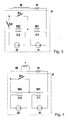
- FIG. 1 An arrangement according to the invention is shown schematically with reference to FIG. 1 , which comprises a superconducting magnet coil system M and a flow pump P.
- the magnet coil system M may have a resistance of the size R.
- two further superconducting coils M1 and M2 are connected in series, which serve as secondary coils in the flow pump P. In these coils can be induced by changing the current I1 or I2 in the primary coils C1 and C2 of the flow pump P by inductive coupling a voltage.
- One of the secondary coils, namely M2 is bridged by a superconductive switch S1 .
- FIG. 2 shows schematically an arrangement according to the invention, in which the secondary coil M2, which is bridged with the superconducting switch S1 , is connected in series with a resistor R2 , such that the switch S1 bridges both the coil M2 and the resistor R2 .
- FIG. 3 shows an arrangement according to the invention as in FIG. 2, with the difference that a second superconductive switch S2 is used instead of the resistor R2 .
- Figure 4 shows an inventive arrangement as in Figure 1, in which in addition a portion of the superconducting magnet coil system M is bridged with a resistor r .
- FIG. 5 shows, for an operating method of the inventive flow pump according to FIG. 3, the currents I1 and I2 in the primary coils C1 and C2 of the flow pump P and the switching states of the superconducting switches S1 and S2 , the current IS1 in the switch S1 and that through the flow pump P above the latter superconducting magnet coil system M built-up voltage VMagnet.
- time t is plotted. The method is optimized to keep the voltage VMagnet constant over any number of pump cycles and to produce no voltage spikes. In addition, the duration during which the superconductive switches are opened is minimized.
- the two switches S1 and S2 are superconductingly closed and the operating current IM of the superconducting magnet coil system M flows via the current path M-M1-. M2-S2.
- the current I2 in the second primary coil C2 is zero and the current I1 in the first primary coil C1 is treated with a continuous ramp of 0.25 A / s during 8s of - loaded 1A + 1A. As a result, a voltage of 25 ⁇ V is induced in the secondary coil M1 .
- the voltage induced in M1 is -100 ⁇ V in this phase .
- the switch S1 is opened and the current in the second primary coil C2 is driven from zero to 2.5A. As a result, a voltage of 125 ⁇ V is induced in the second secondary coil M2 .
- the system is not yet back to its initial state because the current I2 in the second primary coil C2 is not zero.
- I2 When resetting I2 to zero, it must also be ensured that the operating current IM at the end again flows through the secondary coil M2 and not via the closed switch S1 , that is, IS1 should be zero. If this condition is not met, the renewed opening of the switch S1 in the following cycle of the flow pump P generates an undesired voltage pulse across the superconducting magnet coil system M.
- the goal of bringing both I2 and IS1 to zero is achieved by driving I2 to the value - IM * KM2C2 / LM2 between t2 and t3 , in example -1A.
- the switch S2 is opened, whereby the current in M2 is kept at zero.
- the switch S2 is closed again and then, until time t4, the current I2 in the second primary coil C2 is reduced to zero.
- the advantages of this arrangement become clear.
- the voltage over the entire cycle of the flow pump P can be kept constant and there are no voltage spikes when opening superconducting switches.
- the switches are open only during a fraction of the operating cycle of the flow pump P , whereby the heat input in the cryostat through the switches is minimal.
- the requirements for the temporal stability of the magnetic field are particularly high.
- the overall resistivity of the magnet coil system may be at most on the order of 0.1 * 10 -9 ohms for field drift to be acceptable.
- the resistivity of the magnet coil system may therefore be over a thousand times greater than in an arrangement without the inventive flow pump.
- a magnet arrangement according to the invention comprises a superconducting magnet coil system M and at least two superconducting secondary coils M1, M2, which are connected in series with the magnet coil system, and a first superconducting switch S1 , which can superconductingly bridge the second of the secondary coils M2 .
- the magnet arrangement has a second superconducting switch S2 , which is connected in series with the second secondary coil M2 , wherein the first superconducting switch S1 can bridge the entirety of the second secondary coil M2 and the second superconducting switch S2 .
- inductive coupling can be generated by means of at least two independent primary coils C1 , C2 a predetermined voltage in each of the secondary coils M1, M2 , regardless of the other secondary coil.
- the system of secondary coils, primary coils and superconducting switches forms a flux pump P for the magnet coil system. This flux pump can be used well to stabilize the magnetic field of the magnetic coil system in the operating state for a long time, that is, for drift compensation in the magnetic coil system.
Landscapes
- Physics & Mathematics (AREA)
- Electromagnetism (AREA)
- Engineering & Computer Science (AREA)
- Power Engineering (AREA)
- Magnetic Resonance Imaging Apparatus (AREA)
Abstract
Eine Magnetanordnung mit einem supraleitenden Magnetspulensystem ( M ), welches im Betriebszustand einen Ohmschen Widerstand ( R ) größer oder gleich null aufweist, und mit einer Flusspumpe ( P ), welche mindestens einen supraleitenden Schalter und mindestens zwei supraleitende Sekundärspulen ( M1, M2 ) umfasst, ist dadurch gekennzeichnet, dass mindestens ein supraleitender Strompfad vorhanden ist, in welchem das supraleitende Magnetspulensystem ( M ) oder Teile davon mit mindestens zwei Sekundärspulen ( M1, M2 ) zusammen in Serie geschaltet ist und in welchem mindestens eine Sekundärspule ( M2 ) durch Schließen eines supraleitenden Schalters ( S1 ) supraleitend überbrückt werden kann, und dass mindestens zwei Primärspulen ( C1, C2 ) vorhanden sind, welche unabhängig voneinander mit je einem Strom ( I1, I2 ) gespeist werden können und welche jeweils mit mindestens einer der Sekundärspulen ( M1 , M2 ) induktiv gekoppelt sind. Die Flusspumpe kann gut zur Stabilisierung des Magnetfelds des Magnetspulensystems ( M ) im Betriebszustand über lange Zeit eingesetzt werden.A magnet arrangement comprising a superconducting magnet coil system (M) which in operation has an ohmic resistance (R) greater than or equal to zero, and a flux pump (P) comprising at least one superconductive switch and at least two secondary superconducting coils (M1, M2), is characterized in that there is at least one superconducting current path in which the superconducting magnet coil system (M) or parts thereof is connected in series with at least two secondary coils (M1, M2) and in which at least one secondary coil (M2) is formed by closing a superconducting one Switch (S1) can be bridged superconducting, and that at least two primary coils (C1, C2) are present, which can be fed independently with one current (I1, I2) and which in each case with at least one of the secondary coils (M1, M2) are inductively coupled. The flux pump can be used well for stabilizing the magnetic field of the magnetic coil system (M) in the operating state for a long time.
Description
Die Erfindung betrifft eine Magnetanordnung mit einem supraleitenden Magnetspulensystem, welches im Betriebszustand einen Ohmschen Widerstand größer oder gleich null aufweist, und mit einer Flusspumpe, welche mindestens einen supraleitenden Schalter und mindestens zwei supraleitende Sekundärspulen umfasst. The invention relates to a magnet arrangement with a superconducting Magnetic coil system, which in the operating state an ohmic resistance greater than or equal to zero, and with a flow pump, which at least a superconductive switch and at least two superconducting Secondary coils includes.
Eine solche Magnetanordnung mit einem supralteitenden Magnetspulensystem beschreiben T. P. Bernart et al., Rev. Sci. Instrum., Vol. 46, No. 5, May 1975, Seiten 582- 585.Such a magnet arrangement with a superconducting magnet coil system describe T.P. Bernart et al., Rev. Sci. Instrum., Vol. 46, no. 5, May 1975, Pages 582-585.
Das supraleitende Magnetspulensystem umfasst eine oder mehrere in Serie geschaltete Magnetspulen, die einen geschlossenen supraleitenden Stromkreis bilden. Das supraleitende Magnetspulensystem ist typischerweise in einem Kryostaten angeordnet. Es kann im Betriebszustand einen Ohmschen Widerstand größer null aufweisen, wenn die verwendeten Supraleiter bis knapp unter den kritischen Strom belastet sind oder wenn sie keinen scharfen Übergang von supraleitend zu normalleitend aufweisen. Das Prinzip einer Flusspumpe besteht darin, durch induktives Einkoppeln von Energie resistive Verluste der Magnetspule auszugleichen oder die Spule zu laden oder zu entladen, ohne dass große Ströme in den Kryostaten geführt werden müssen. Die Erfindung betrifft insbesondere supraleitende Magnetspulensysteme mit einer Flusspumpe, welche mindestens einen supraleitenden Schalter und mindestens zwei supraleitende Sekundärspulen umfasst, in welchen induktiv eine Spannung aufgebaut werden kann. Damit diese Spannung zum Ausgleich resisitiver Verluste oder zum Laden oder Entladen in das supraleitende Magnetspulensystem eingespeist werden kann, müssen die Sekundärspulen supraleitend mit dem Magnetspulensystem in Serie geschaltet sein, was beispielsweise durch Schließen eines supraleitenden Schalters erfolgen kann.The superconducting magnet coil system includes one or more in series switched magnetic coils, which form a closed superconducting circuit form. The superconducting magnet coil system is typically in one Cryostats arranged. It can be ohmic in the operating state Resistance greater than zero, if the superconductors used until just under are under the critical load or if they are not sharp Transition from superconducting to normal conducting. The principle of a Flow pump is made by inductive coupling of energy resistive To compensate for losses of the solenoid or to load the coil or to discharged without large currents must be performed in the cryostat. The invention particularly relates to superconducting magnet coil systems a flow pump, which at least one superconducting switch and comprises at least two superconducting secondary coils, in which inductively a tension can be built up. So that tension to compensate Resisitiver losses or to charge or discharge in the superconducting Magnetic coil system can be fed, the secondary coils Superconducting to be connected in series with the magnetic coil system, which for example, by closing a superconducting switch.
Eine Magnetanordnung mit einer Flusspumpe, welche mindestens zwei
supraleitende Sekundärspulen umfasst, ist bekannt aus T.P. Bernat et. al., Rev.
Sci. Instrum., Vol. 46, No 5, May 1975, und aus L.J.M. van de Klundert et. al.,
Cryogenics, May 1981. Diese Flusspumpe basiert darauf, dass das supraleitende
Magnetspulensystem mit zwei Strompfaden überbrückt wird, welche je einen
Schalter und eine supraleitende Sekundärspule umfassen. In einer Primärspule,
deren induktive Kopplung mit den Sekundärspulen je entgegengesetzt gleich
groß ist, wird zyklisch Strom ein und wieder ausgefahren. Wenn im gleichen Takt
die mit den Sekundärspulen in Serie geschalteten supraleitenden Schalter
alternierend geöffnet und geschlossen werden, entsteht über dem
Magnetspulensystem eine über den ganzen Zyklus konstante Spannung,
abgesehen von Spannungsspitzen beim Öffnen der Schalter.A magnet arrangement with a flow pump, which is at least two
Superconducting secondary coils is known from T.P. Bernat et. al., Rev.
Sci. Instrum., Vol. 46,
Das typische Einsatzgebiet von Flusspumpen ist das Laden und Entladen von supraleitenden Magnetspulensystemen. Der Vorteil gegenüber dem direkten Einspeisen des Betriebsstromes in die Spulen besteht darin, dass die Ströme zum Betreiben der Flusspumpe viel schwächer sind als die typischen Magnetströme. Damit können die Stromzuleitungen kleiner dimensioniert und der Wärmeeintrag in den Kryostaten reduziert werden.The typical application of flow pumps is the loading and unloading of superconducting magnet coil systems. The advantage over the direct Feeding the operating current into the coils is that the currents to operate the river pump are much weaker than the typical ones Magnetic currents. Thus, the power supply lines can be made smaller and the Heat input in the cryostat can be reduced.
Das Einsatzgebiet von supraleitenden Magneten umfasst aber auch Anwendungsfelder, bei denen die Magnetspulen nach dem Ladevorgang über Jahre auf Feld bleiben und dabei eine möglichst geringe Felddrift aufweisen sollen. Dazu gehören insbesondere supraleitende Magnetspulensysteme für Magnetresonanzverfahren. Bei solchen Magnetsystemen ist der Einsatz einer Flusspumpe weniger zum Laden des Magnetsystems von Interesse, sondern zur Stabilisierung des Magnetfeldes im Betriebszustand. Eine effiziente Flusspumpe brächte in dieser Hinsicht verschiedene Vorteile. Es könnten beispielsweise Magnete mit Teilspulen aus Hochtemperatursupraleitern gebaut werden, welche nach heutigem Stand der Technik die Driftspezifikationen für Magnetresonanzanwendungen ohne zusätzliche Maßnahmen nicht erfüllen. Dies würde den Bau von Magneten mit stärkeren als den heute üblichen Feldern ermöglichen. Weiter könnten durch den Einsatz einer Flusspumpe zur Feldstabilisierung die Supraleiter im Magneten höher belastet werden, was den Bau kompakterer und kostengünstigerer Magnete erlauben würde.The field of application of superconducting magnets also includes Fields of application in which the solenoid coils over the charging process Stay on the field for years and have the lowest possible field drift should. These include in particular superconducting magnet coil systems for Magnetic resonance methods. In such magnet systems, the use of a Flow pump less for charging the magnet system of interest, but for Stabilization of the magnetic field in the operating state. An efficient flow pump would bring various advantages in this regard. It could for example Magnets with partial coils are built from high-temperature superconductors, which According to the current state of the art, the drift specifications for Do not meet magnetic resonance applications without additional measures. This would be the construction of magnets with stronger than the usual fields today enable. Further, by using a flow pump for Field stabilization the superconductors in the magnet are charged higher, which the Construction of more compact and less expensive magnets would allow.
Für den Einsatz zur präzisen Feldstabilisierung über große Zeiträume sind die bekannten Flusspumpen nicht geeignet. Zum einen treten jeweils beim Öffnen von supraleitenden Schaltern Spannungsspitzen über dem Magnetspulensystem auf, was für empfindliche Anwendungen wie Magnetresonanzverfahren nicht tolerierbar ist. Zum andern muss in jeder Phase des Pumpzyklus mindestens ein supraleitender Schalter geöffnet sein, damit die in der Sekundärspule induzierte Spannung in das Magnetspulensystem eingespeist werden kann. Bei den gebräuchlichen Schaltern fällt dabei eine Wärmemenge an, welche zu großen Verlusten an Kühlflüssigkeit im Kryostaten führt. Für die Stabilität des Feldes ist auch die thermische Stabilität im Kryostaten sehr wichtig, das heißt bei empfindlichen Anwendungen wie Magnetresonanzverfahren müssen die Wärmeeinträge in den Kryostaten minimiert werden.For use for precise field stabilization over long periods, the known flow pumps not suitable. Firstly, each time you open of superconducting switches voltage spikes across the magnet coil system which is not for sensitive applications such as magnetic resonance is tolerable. On the other hand, at least one must be in each phase of the pumping cycle Superconducting switch should be open so that induced in the secondary coil Voltage can be fed into the magnet coil system. Both Usual switches falls while a quantity of heat, which is too large Loss of coolant in the cryostat leads. For the stability of the field is Also, the thermal stability in the cryostat very important, that is at sensitive applications such as magnetic resonance have to be Heat entries in the cryostat are minimized.
Aufgabe der vorliegenden Erfindung ist es, eine Flusspumpe gemäß dem Stand der Technik derart zu verbessern, dass neben dem Laden und Entladen eines supraleitenden Magnetspulensystems auch eine gute Stabilisierung des Magnetfeldes des Magnetspulensystems im Betriebszustand über lange Zeit möglich ist, insbesondere dann, wenn das Magnetspulensystem leicht resisitiv ist und die Anforderungen an die Feldstabilität sehr hoch sind. Insbesondere ist es Aufgabe der vorliegenden Erfindung, dass die verbesserte Flusspumpenanordnung ein Betriebsverfahren zulässt, mit welchem eine über alle Zyklen der Flusspumpe konstante Spannung über dem Magnetspulensystem angelegt werden kann.Object of the present invention is a flow pump according to the prior the technique to improve so that in addition to the loading and unloading of a superconducting magnet coil system also good stabilization of the Magnetic field of the magnetic coil system in the operating state for a long time is possible, especially when the magnetic coil system is easily resists and the field stability requirements are very high. In particular it is Object of the present invention that the improved Flow pump assembly allows an operating method, with which an over all cycles of the flow pump constant voltage across the solenoid system can be created.
Erfindungsgemäß wird diese Aufgabe bei einer Magnetanordnung der eingangs vorgestellten Art dadurch gelöst, dass mindestens ein supraleitender Strompfad vorhanden ist, in welchem das supraleitende Magnetspulensystem oder Teile davon mit mindestens zwei Sekundärspulen zusammen in Serie geschaltet ist und in welchem mindestens eine Sekundärspule durch Schließen eines supraleitenden Schalters supraleitend überbrückt werden kann, und dass mindestens zwei Primärspulen vorhanden sind, welche unabhängig voneinander mit je einem Strom gespeist werden können und welche jeweils mit mindestens einer der Sekundärspulen induktiv gekoppelt sind.This object is achieved in a magnet arrangement of the initially solved type solved by at least one superconducting current path is present, in which the superconducting magnet coil system or parts thereof connected in series with at least two secondary coils and in which at least one secondary coil by closing a Superconducting switch superconducting can be bridged, and that at least two primary coils are present, which are independent of each other can be fed with one power and each with at least one of the secondary coils are inductively coupled.
Kurz gesagt sieht die Erfindung vor, dass ein supraleitender Strompfad vorhanden ist, in welchem das supraleitende Magnetspulensystem oder Teile davon mit mindestens zwei Sekundärspulen zusammen in Serie geschaltet ist und in welchem mindestens eine Sekundärspule durch Schließen eines supraleitenden Schalters überbrückt werden kann. Insbesondere kann vorgesehen sein, dass die Sekundärspulen mit je einer eigenen Primärspule induktiv gekoppelt sind.In short, the invention provides that a superconducting current path is present, in which the superconducting magnet coil system or parts thereof connected in series with at least two secondary coils and in which at least one secondary coil by closing a Superconducting switch can be bridged. In particular, can be provided that the secondary coils, each with its own primary coil are inductively coupled.
Diese Anordnung ermöglicht ein Betriebsverfahren der Flusspumpe, bei welchem in einem ersten Schritt eine erste Primärspule, welche mit einer ersten, nicht supraleitend überbrückten Sekundärspule gekoppelt ist, geladen wird, bis in der Primärspule ein maximaler Endstrom erreicht ist. Dadurch kann eine Spannung über dem supraleitenden Magnetspulensystem aufgebaut werden, welche beispielsweise genau der zu kompensierenden resistiven Spannung im Magnetspulensystem entspricht. In einem zweiten Schritt muss die erste Primärspule wieder auf ihren Anfangsstrom entladen werden. Während dieser Phase wird über einer zweiten, zuvor mit einem geschlossenen Schalter supraleitend überbrückten Sekundärspule der supraleitende Schalter geöffnet und in jener Primärspule, welche mit dieser Sekundärspule induktiv koppelt, der Strom hochgefahren, wodurch in dieser Sekundärspule eine Spannung induziert wird. Die Stromrampe in der zweiten Primärspule wird so gewählt, dass durch die in der zweiten Sekundärspule induzierte Spannung sowohl die durch das Entladen der ersten Primärspule in der ersten Sekundärspule induzierte Spannung als auch die resisitve Spannung über dem supraleitenden Magnetspulensystem kompensiert wird. Nachdem die erste Primärspule auf ihrem Anfangsstrom angelangt ist, wird der Schalter über der zweiten Sekundärspule wieder geschlossen und die zweite Primärspule wird - bei geschlossenem Schalter - auf ihren Anfangsstrom zurückgefahren. Der Zyklus kann nun von vorn beginnen.This arrangement enables an operation method of the flow pump in which in a first step, a first primary coil, which with a first, not coupled superconducting bridged secondary coil is charged until in the Primary coil a maximum final current is reached. This can be a tension be built over the superconducting magnet coil system, which for example, exactly the resistive voltage to be compensated in the Magnetic coil system corresponds. In a second step, the first Primary coil are discharged back to their initial current. During this Phase is over a second, previously with a closed switch superconducting bridged secondary coil of the superconducting switch opened and in that primary coil which inductively couples to this secondary coil, the Power up, which induces a voltage in this secondary coil becomes. The current ramp in the second primary coil is chosen so that through the in the second secondary coil induced voltage both through the Discharging the first primary coil induced in the first secondary coil Voltage as well as the resisitve voltage across the superconducting Magnetic coil system is compensated. After the first primary coil on has reached its initial current, the switch over the second Secondary coil closed again and the second primary coil - at closed switch - moved back to its initial current. The cycle can now start over.
Der Vorteil einer erfindungsgemäßen Anordnung ist also, dass dank mehreren voneinander unabhängig mit Strom versorgten Primärspulen in verschiedenen Sekundärspulen unterschiedliche Spannungen induziert werden können, welche dank der Serieschaltung dieser Sekundärspulen zu einer Gesamtspannung addiert werden. Die Serieschaltung der Sekundärspulen mit dem supraleitenden Magnetspulensystem erlaubt die Einspeisung dieser Gesamtspannung in das supraleitende Magnetspulensystem. Die große Flexibilität der Anordnung ermöglicht, dass durch geeignete Verfahrensschritte in jeder Phase des Flusspumpen-Zyklus eine gewünschte Spannung über dem supraleitenden Magnetspulensystem aufrechterhalten werden kann.The advantage of an arrangement according to the invention is therefore that thanks to several independently supplied primary coils in different Secondary coils different voltages can be induced, which thanks to the series connection of these secondary coils to a total voltage be added. The series connection of the secondary coils with the superconducting Magnetic coil system allows the supply of this total voltage in the superconducting magnet coil system. The great flexibility of the arrangement allows that through appropriate process steps in each phase of the Flow pump cycle a desired voltage across the superconducting Magnetic coil system can be maintained.
Es zeigt sich, dass beim oben beschriebenen Betriebsverfahren der Flusspumpe während dem ganzen Zyklus zu keiner Zeit ein supraleitender Kurzschluss über der ersten Sekundärspule bestehen muss. Dies bedeutet, dass erfindungsgemäß von n ≥ 2 Sekundärspulen höchstens n-1 Sekundärspulen mit einem Schalter überbrückt werden müssen. Im einfachsten Falle von n = 2 wird also nur ein einziger Schalter benötigt, welcher zudem nur während der kurzen Zeit, während welcher der Strom in der ersten Primärspule zurückgesetzt wird, geöffnet sein muss. Dadurch wird die Wärmeleistung durch die Schalterheizer gegenüber einer Flusspumpe nach dem Stand der Technik deutlich reduziert. Diese Ausführungsform der Erfindung ist daher besonders vorteilhaft.It turns out that in the above-described operation method of the flow pump at any time during the entire cycle must be a superconducting short circuit on the first secondary coil. This means that according to the invention of n ≥ 2 secondary coils at most n-1 secondary coils must be bridged with a switch. In the simplest case of n = 2 , therefore, only a single switch is required, which in addition only has to be open during the short time during which the current in the first primary coil is reset. As a result, the heat output is significantly reduced by the switch heater over a prior art flow pump. This embodiment of the invention is therefore particularly advantageous.
Bevorzugt ist außerdem eine Ausführungsform der erfindungsgemäßen Anordnung, bei welcher ein supraleitender Schalter eine Sekundärspule zusammen mit einem Widerstand überbrückt, welcher mit dieser Sekundärspule in Serie geschaltet ist, wobei der Widerstand einen Wert, gemessen in Ohm, zwischen 0 und dem Wert der Induktivität dieser Sekundärspule, gemessen in Henry, aufweist. Der Vorteil dieser Anordnung liegt darin, dass beim Laden und Entladen einer Primärspule, welche mit dieser Sekundärspule induktiv gekoppelt ist, bei geschlossenem supraleitendem Schalter keine unkontrolliert hohen Ströme in der Sekundärspule induziert werden können.In addition, an embodiment of the invention is preferred Arrangement in which a superconducting switch, a secondary coil bridged together with a resistor, which with this secondary coil is connected in series, the resistor having a value, measured in ohms, between 0 and the value of the inductance of this secondary coil, measured in Henry, has. The advantage of this arrangement is that when loading and Discharging a primary coil which is inductively coupled to this secondary coil is not uncontrollably high when the superconducting switch is closed Currents in the secondary coil can be induced.
Eine besonders bevorzugte Ausführungsform der erfindungsgemäßen Anordnung zeichnet sich dadurch aus, dass anstatt des in obiger Ausführungsform verwendeten Widerstandes ein weiterer supraleitender Schalter verwendet wird. Diese Ausführungsform sieht somit vor, dass ein supraleitender Schalter eine Sekundärspule zusammen mit einem weiteren supraleitenden Schalter überbrückt, welcher mit der genannten Sekundärspule in Serie geschaltet ist; siehe auch Figur 3. Dadurch lässt sich durch geeignetes Laden und Entladen der zugehörigen Primärspule sowie durch Öffnen und Schließen des weiteren Schalters der Strom in der Sekundärspule gezielt steuern. Insbesondere kann so verhindert werden, dass vor dem Öffnen des ersten Schalters an einem bestimmten Punkt des Pumpzyklus ein Strom über diesen Schalter fließt. Damit werden Spannungspulse über dem supraleitenden Magnetspulensystem verhindert, was insbesondere bei empfindlichen Anwendungen wie Kernspinresonanzverfahren unumgänglich ist. Außerdem wird im ersten Schalter keine Wärme durch den Abbau von Strom erzeugt, was eine weitere Ersparnis an Kühlflüssigkeit ermöglicht. Diese Anordnung ermöglicht die Anwendung eines Betriebsverfahrens der Flusspumpe, welches eine ungestörte, kontinuierliche Pumpleistung bei einem Minimum an Wärmeeintrag in den Kryostaten garantiert.A particularly preferred embodiment of the invention Arrangement is characterized by the fact that instead of the above Embodiment used resistor another superconducting switch is used. This embodiment thus provides that a superconducting Switch a secondary coil together with another superconducting one Switch bridged, which with the said secondary coil in series is switched; See also Figure 3. This can be done by appropriate loading and unloading the associated primary coil and by opening and closing the other switch the power in the secondary coil control. In particular, can be prevented so that before opening the first Switch at a certain point of the pumping cycle, a current over this Switch flows. This causes voltage pulses above the superconducting Magnetic coil system prevents, especially in sensitive Applications such as nuclear magnetic resonance method is inevitable. In addition, will in the first switch no heat generated by the removal of electricity, causing a further savings on cooling liquid allows. This arrangement allows the Application of a method of operation of the flow pump, which is an undisturbed, continuous pumping power with a minimum of heat input into the Cryostats guaranteed.
In zwei weiteren vorteilhaften Ausführungsformen der erfindungsgemäßen Anordnung werden Sekundärspulen mit je genau einer Primärspule induktiv gekoppelt, oder Sekundärspulen werden voneinander induktiv entkoppelt. Dadurch können die in den Sekundärspulen beim Laden oder Entladen der Primärspulen induzierten Spannungen besser kontrolliert werden und die Verfahren zum Betrieb der Flusspumpe werden vereinfacht.In two further advantageous embodiments of the invention Arrangement secondary coils, each with exactly one primary coil inductive coupled, or secondary coils are inductively decoupled from each other. This can be used in the secondary coils when charging or discharging the Primary coil induced voltages are better controlled and the Procedures for operating the flow pump are simplified.
Besonders vorteilhaft sind auch Ausführungsformen der erfindungsgemäßen Anordnung, bei welchen Primär- oder Sekundärspulen vom supraleitenden Magnetspulensystem induktiv weitgehend entkoppelt sind oder im Arbeitsvolumen des supraleitenden Magnetspulensystems im wesentlichen kein Feld erzeugen. So werden Störungen des Magnetfeldes im Arbeitsvolumen während dem Betrieb der Flusspumpe verhindert.Embodiments of the invention are also particularly advantageous Arrangement in which primary or secondary coils of the superconducting Magnetic coil system inductively largely decoupled or in Working volume of the superconducting magnet coil system essentially no Create field. Thus, disturbances of the magnetic field in the working volume prevented during operation of the flow pump.
Eine weitere vorteilhafte Ausführungsform der erfindungsgemäßen Anordnung zeichnet sich dadurch aus, dass mindestens eine Primärspule supraleitend ist. Ein in einer supraleitenden Primärspulen fließender Strom erzeugt im Gegensatz zu normalleitenden Primärspulen keine Wärme. Falls sich die Primärspulen im Kryostaten befinden, können so die Kühlmittelverluste reduziert werden.A further advantageous embodiment of the arrangement according to the invention is characterized by the fact that at least one primary coil is superconducting. In contrast, a current flowing in a superconducting primary coil generates to normal conducting primary coils no heat. If the primary coils are in the Cryostats are located, so the coolant losses can be reduced.
Eine weitere Verbesserung hinsichtlich Reduktion der Kühlmittelverluste wird erreicht, wenn auch die Zuleitungen zu den Spulen im Kryostaten oder zu den Schaltern mindestens teilweise supraleitend ausgeführt werden.Another improvement in terms of reducing coolant losses is reached, although the leads to the coils in the cryostat or to the Switches are carried out at least partially superconducting.
Eine andere Ausführungsform sieht vor, dass mindestens einer der supraleitenden Schalter durch einen Heizer betätigbar ist, dessen Zuleitungen mindestens teilweise supraleitend sind.Another embodiment provides that at least one of superconducting switch can be actuated by a heater whose supply lines at least partially superconducting.
Eine vorteilhafte Ausführungsform der erfindungsgemäßen Anordnung zeichnet sich dadurch aus, dass mindestens ein Abschnitt des supraleitenden Magnetspulensystems supraleitend oder mit einem Widerstand überbrückt ist. Diese Anordnung kann dazu verwendet werden, um die Auswirkung von kleinen Spannungsfluktuationen, etwa beim Öffnen von Schaltern der Flusspumpe, auf das Gesamtfeld des supraleitenden Magnetsystems zu dämpfen. Damit die Dämpfung wirksam ist, darf der Widerstand (in Ohm) die Größenordnung der Induktivität (in Henry) des überbrückten Abschnittes nicht übersteigen.An advantageous embodiment of the arrangement according to the invention is characterized characterized by having at least a portion of the superconducting Magnet coil system is superconducting or bridged with a resistor. This arrangement can be used to reduce the impact of small Voltage fluctuations, such as when opening switches of the flow pump on to dampen the entire field of the superconducting magnet system. So that Damping is effective, the resistance (in ohms) may be the order of magnitude Do not exceed inductance (in Henry) of the bridged section.
Die erfindungsgemäße Anordnung ist besonders dann vorteilhaft, wenn sie Teil einer Apparatur für die magnetische Kernspinresonanz ist. In solchen Magnetanordnungen werden an eine Vorrichtung zur aktiven Feldstabilisierung, als welche die erfindungsgemäße Flusspumpe in diesem Anwendungsgebiet bevorzugt eingesetzt wird, besonders hohe Anforderungen hinsichtlich Konstanz der Stabilisierungsspannung und Minimierung des Wärmeeintrages in den Kryostaten gestellt. Genau diese Kriterien werden in den oben aufgeführten Ausführungsformen der erfindungsgemäßen Flusspumpe besser erfüllt als mit Flusspumpen nach dem Stand der Technik.The arrangement according to the invention is particularly advantageous when it is part a magnetic resonance magnetic resonance apparatus. In such Magnetic arrangements are connected to an apparatus for active field stabilization, as which the flow pump according to the invention in this field of application is preferably used, particularly high requirements in terms of constancy the stabilization voltage and minimize the heat input in the Cryostats asked. Exactly these criteria are listed in the above Embodiments of the flow pump according to the invention better fulfilled than with River pumps according to the prior art.
Eine vorteilhafte Ausführungsform der erfindungsgemäßen Anordnung umfasst ein supraleitendes Magnetspulensystem, in welchem eine oder mehrere Spulen mit Hochtemperatursupraleitern gewickelt sind. Die potentiell höhere Drift bei Verwendung von Hochtemperatursupraleitern lässt sich mit der erfindungsgemäßen Flusspumpe kompensieren, unter Beibehaltung der Feldstabilität des supraleitenden Magnetspulensystems.An advantageous embodiment of the inventive arrangement comprises a superconducting magnet coil system in which one or more coils are wound with high temperature superconductors. The potentially higher drift at Use of high temperature superconductors can be with the compensate flow pump according to the invention, while maintaining the Field stability of the superconducting magnet coil system.
Die Vorteile der erfindungsgemäßen Anordnung können nur unter Anwendung von geeigneten Verfahren zum Betrieb der Flusspumpe voll ausgeschöpft werden. Ein erstes Verfahren zeichnet sich durch einen besonders einfachen Zyklus von Laden und Entladen der Primärspulen und Öffnen und Schließen der Schalter aus. Bei diesem Verfahren zum Betrieb einer Vorrichtung mit mindestens einer ersten und einer zweiten supraleitenden Sekundärspule und einem ersten supraleitenden Schalter wird der erste supraleitende Schalter, welcher die zweite Sekundärspule überbrückt, periodisch geöffnet und geschlossen. Bei geschlossenem erstem Schalter wird der Strom in einer ersten Primärspule, welche mit der ersten Sekundärspule induktiv koppelt, von einem Anfangswert auf einen Endwert gefahren. Bei geöffnetem erstem Schalter wird der Strom in dieser Primärspule wieder weitgehend auf den Anfangswert zurückgesetzt. Gleichzeitig wird bei geöffnetem erstem Schalter der Strom in einer zweiten Primärspule, welche mit der zweiten Sekundärspule koppelt, von einem Anfangswert auf einen Endwert gefahren und bei geschlossenem erstem Schalter wieder weitgehend auf den Anfangswert zurückgesetzt.The advantages of the arrangement according to the invention can only be applied fully utilized by appropriate procedures for operating the flow pump become. A first method is characterized by a particularly simple Cycle of loading and unloading of the primary reels and opening and closing of the reels Switch off. In this method for operating a device with at least a first and a second superconducting secondary coil and a first superconducting switch becomes the first superconducting switch, which bypasses the second secondary coil, periodically opened and closed. When the first switch is closed, the current in a first Primary coil, which inductively couples with the first secondary coil of a Initial value driven to a final value. When the first switch is open the current in this primary coil again largely to the initial value reset. At the same time, when the first switch is open, the current is switched on a second primary coil which couples with the second secondary coil of moved to an initial value to a final value and closed first Switch again largely reset to the initial value.
Ein verbessertes Verfahren unter Verwendung des weiteren, zweiten supraleitenden Schalters zeichnet sich dadurch aus, dass bei geschlossenem erstem Schalter ein zweiter supraleitender Schalter, welcher mit der zweiten Sekundärspule in Serie geschaltet ist und zusammen mit dieser vom ersten supraleitenden Schalter überbrückt wird, mindestens zeitweise geöffnet wird. Der Vorteil dieses Verfahrens ist, dass sich die zweite Sekundärspule beim Zurücksetzen des Stromes in der zweiten Primärspule nicht unkontrolliert auflädt. An improved method using the further, second superconducting switch is characterized in that when closed first switch a second superconducting switch, which with the second Secondary coil is connected in series and together with this from the first superconducting switch is bridged, at least temporarily opened. Of the Advantage of this method is that the second secondary coil during Resetting the current in the second primary coil does not charge uncontrollably.
Besonders vorteilhaft ist es, den Strom in der zweiten Primärspule jeweils wieder auf null zurückzufahren, um weniger Wärme in den Zuleitungen und - im Falle einer normalleitenden zweiten Primärspule - in der Spule selbst zu erzeugen.It is particularly advantageous to restore the current in the second primary coil in each case to reduce to zero, less heat in the supply lines and - in the case a normally-conductive second primary coil - to produce in the coil itself.
Diese Verfahrensvariante kann weiter verbessert werden, indem vor Erreichen des Endstromes von null Ampere in der zweiten Primärspule der Strom in dieser Spule auf einen Betrag von I * L / K gesetzt wird und dass spätestens nach Erreichen dieses Stromes der zweite supraleitende Schalter geöffnet wird, und dass dann während dem Zurücksetzen des Stromes in der zweiten Primärspule auf den Endstrom von null Ampere und bis zum neuerlichen Öffnen des ersten supraleitenden Schalters der zweite supraleitende Schalter supraleitend geschlossen bleibt, wobei /den Strom im supraleitenden Magnetspulensystem, L die Selbstinduktivität der zweiten Sekundärspule und K die induktive Kopplung in Henry zwischen der zweiten Sekundärspule und der zweiten Primärspule bezeichnet. Dieses Verfahren wird im untenstehenden Beispiel genauer beschrieben. Sein besonderer Vorteil ist, dass vor dem Öffnen des ersten supraleitenden Schalters kein Strom über diesen fließt. So werden Spannungsspitzen über dem supraleitenden Magnetspulensystem verhindert, was für den Einsatz der erfindungsgemäßen Flusspumpe zur Feldstabilisierung bei empfindlichen Anwendungen ein wichtiges Kriterium darstellt.This process variant can be further improved by setting the current in this coil to an amount of I * L / K before reaching the final current of zero amperes in the second primary coil and that the second superconducting switch is opened at the latest after reaching this current, and that then, while resetting the current in the second primary coil to the final current of zero amperes and until the first opening of the first superconducting switch, the second superconducting switch remains superconducting closed, the current in the superconducting magnet coil system, L the self-inductance of the second secondary coil and K denoting the inductive coupling in Henry between the second secondary coil and the second primary coil. This process is described in more detail in the example below. Its particular advantage is that no current flows over it before opening the first superconducting switch. Thus, voltage peaks are prevented over the superconducting magnet coil system, which is an important criterion for the use of the flow pump according to the invention for field stabilization in sensitive applications.
In zwei weiteren vorteilhaften Verfahrensvarianten werden die Schritte der beschriebenen Verfahren zyklisch wiederholt, um das supraleitende Magnetspulensystem entweder zu laden oder zu entladen, oder um den Strom im Magnetspulensystem auf einem Betriebswert genau zu stabilisieren.In two further advantageous variants of the method, the steps of cyclic repeated to the superconducting Magnetic coil system either to charge or discharge, or to the power to stabilize accurately in the magnet coil system to an operating value.
Die erfindungsgemäße Anordnung erlaubt auch die Anwendung einer hinsichtlich Reduktion des Wärmeeintrages in den Kryostaten besonders vorteilhaften Verfahrensvariante, bei welcher jene Phase des Pumpzyklus, während welcher kein supraleitender Schalter geöffnet ist, länger dauert als die Phasen mit geöffneten, also geheizten, supraleitenden Schaltern. Demgegenüber müssen bei Flusspumpen nach dem Stand der Technik permanent Schalter geheizt werden.The inventive arrangement also allows the application of a respect Reduction of heat input in the cryostat particularly advantageous Process variant in which that phase of the pumping cycle, during which no superconducting switch is open, lasts longer than the phases with open, so heated, superconducting switches. In contrast, must in flow pumps according to the prior art permanently heated switch become.
Weitere Vorteile der Erfindung ergeben sich aus der Beschreibung und der Zeichnung. Ebenso können die vorstehend genannten und die noch weiter ausgeführten Merkmale erfindungsgemäß jeweils einzeln für sich oder zu mehreren in beliebigen Kombinationen Verwendung finden. Die gezeigten und beschriebenen Ausführungsformen sind nicht als abschließende Aufzählung zu verstehen, sondern haben vielmehr beispielhaften Charakter für die Schilderung der Erfindung.Further advantages of the invention will become apparent from the description and the Drawing. Likewise, those mentioned above and even further executed features according to the invention in each case individually or to several in any combination use find. The shown and described embodiments are not to be exhaustive enumeration but rather have an exemplary character for the description the invention.
Die Erfindung ist in der Zeichnung dargestellt und wird anhand eines Ausführungsbeispiels näher erläutert. Es zeigen:
- Fig. 1
- ein Verdrahtungsschema einer erfindungsgemäßen Magnetanordnung mit einem supraleitenden Magnetspulensystem und einer Flusspumpe;
- Fig. 2
- ein Verdrahtungsschema einer erfindungsgemäßen Magnetanordnung mit einem supraleitenden Magnetspulensystem und einer Flusspumpe mit einem zusätzlichen Widerstand im Strompfad der Flusspumpe;
- Fig. 3
- ein Verdrahtungsschema einer erfindungsgemäßen Magnetanordnung mit einem supraleitenden Magnetspulensystem und einer Flusspumpe mit einem zusätzlichen supraleitenden Schalter im Strompfad der Flusspumpe;
- Fig. 4
- ein Verdrahtungsschema einer erfindungsgemäßen Magnetanordnung mit einem supraleitenden Magnetspulensystem und einer Flusspumpe und einem zusätzlichen Widerstand, welcher einen Abschnitt des supraleitenden Magnetspulensystems überbrückt;
- Fig. 5
- die Ströme und Schalterzustände der Flusspumpe sowie die über dem supraleitenden Magnetspulensystem aufgebaute Spannung während mehrerer Pumpzyklen für ein besonders vorteilhaftes Verfahren zum Betrieb einer erfindungsgemäßen Flusspumpe.
- Fig. 1
- a wiring diagram of a magnet assembly according to the invention with a superconducting magnet coil system and a flow pump;
- Fig. 2
- a wiring diagram of a magnet assembly according to the invention with a superconducting magnet coil system and a flow pump with an additional resistance in the current path of the flow pump;
- Fig. 3
- a wiring diagram of a magnet assembly according to the invention with a superconducting magnet coil system and a flow pump with an additional superconducting switch in the current path of the flow pump;
- Fig. 4
- a wiring diagram of a magnet assembly according to the invention with a superconducting magnet coil system and a flux pump and an additional resistor which bridges a portion of the superconducting magnetic coil system;
- Fig. 5
- the currents and switch states of the flow pump and the voltage built up across the superconducting magnet coil system during several pump cycles for a particularly advantageous method for operating a flow pump according to the invention.
Anhand der Figur 1 wird schematisch eine erfindungsgemäße Anordnung gezeigt, welche ein supraleitendes Magnetspulensystem M und eine Flusspumpe P umfasst. Das Magnetspulensystem M kann einen Widerstand der Größe R aufweisen. Mit dem Magnetspulensystem M sind zwei weitere supraleitende Spulen M1 und M2 in Serie geschaltet, welche in der Flusspumpe P als Sekundärspulen dienen. In diesen Spulen kann durch Veränderung des Stromes I1 beziehungsweise I2 in den Primärspulen C1 beziehungsweise C2 der Flusspumpe P durch induktive Kopplung eine Spannung induziert werden. Eine der Sekundärspulen, nämlich M2, ist mit einem supraleitenden Schalter S1 überbrückt.An arrangement according to the invention is shown schematically with reference to FIG. 1 , which comprises a superconducting magnet coil system M and a flow pump P. The magnet coil system M may have a resistance of the size R. With the magnet coil system M , two further superconducting coils M1 and M2 are connected in series, which serve as secondary coils in the flow pump P. In these coils can be induced by changing the current I1 or I2 in the primary coils C1 and C2 of the flow pump P by inductive coupling a voltage. One of the secondary coils, namely M2, is bridged by a superconductive switch S1 .
Figur 2 zeigt schematisch eine erfindungsgemäße Anordnung, bei welcher die Sekundärspule M2, welche mit dem supraleitenden Schalter S1 überbrückt wird, mit einem Widerstand R2 in Serie geschaltet ist, derart dass der Schalter S1 sowohl die Spule M2 als auch den Widerstand R2 überbrückt. Figure 2 shows schematically an arrangement according to the invention, in which the secondary coil M2, which is bridged with the superconducting switch S1 , is connected in series with a resistor R2 , such that the switch S1 bridges both the coil M2 and the resistor R2 .
Figur 3 zeigt eine erfindungsgemäße Anordnung wie in Figur 2, mit dem Unterschied, dass anstelle des Widerstandes R2 ein zweiter supraleitender Schalter S2 verwendet wird. FIG. 3 shows an arrangement according to the invention as in FIG. 2, with the difference that a second superconductive switch S2 is used instead of the resistor R2 .
Figur 4 zeigt eine erfindungsgemäße Anordnung wie in Figur 1, bei welcher zusätzlich ein Abschnitt des supraleitenden Magnetspulensystems M mit einem Widerstand r überbrückt wird. Figure 4 shows an inventive arrangement as in Figure 1, in which in addition a portion of the superconducting magnet coil system M is bridged with a resistor r .
Figur 5 zeigt für ein Betriebsverfahren der erfindungsgemäßen Flusspumpe nach Figur 3 die Ströme I1 und I2 in den Primärspulen C1 und C2 der Flusspumpe P sowie die Schaltzustände der supraleitenden Schalter S1 und S2, den Strom IS1 im Schalter S1 und die durch die Flusspumpe P über dem supraleitenden Magnetspulensystem M aufgebaute Spannung VMagnet. Nach rechts ist die Zeit t aufgetragen. Das Verfahren ist dahingehend optimiert, die Spannung VMagnet über beliebig viele Pumpzyklen konstant zu halten und keine Spannungsspitzen zu erzeugen. Außerdem wird die Dauer, während der die supraleitenden Schalter geöffnet sind, minimiert. FIG. 5 shows, for an operating method of the inventive flow pump according to FIG. 3, the currents I1 and I2 in the primary coils C1 and C2 of the flow pump P and the switching states of the superconducting switches S1 and S2 , the current IS1 in the switch S1 and that through the flow pump P above the latter superconducting magnet coil system M built-up voltage VMagnet. To the right, time t is plotted. The method is optimized to keep the voltage VMagnet constant over any number of pump cycles and to produce no voltage spikes. In addition, the duration during which the superconductive switches are opened is minimized.
Im Folgenden wird die Erfindung anhand eines Beispiels erläutert. Die dem
Beispiel zu Grunde gelegte Ausführungsform der erfindungsgemäßen Anordnung
ist jene aus Figur 3. Das angewendete Verfahren zum Betrieb der Flusspumpe P
ist jenes aus Figur 5. Das Ziel ist es, über einem supraleitenden
Magnetspulensystem M eine konstante Spannung VMagnet von 25µV
aufrechtzuerhalten. Die Komponenten der Flusspumpe sind folgendermaßen
ausgelegt:
Zu Beginn und während der ersten Phase des Zyklus der Flusspumpe P von t = 0 bis t1 = 8s (siehe Figur 5) sind die beiden Schalter S1 und S2 supraleitend geschlossen und der Betriebsstrom IM des supraleitenden Magnetspulensystems M fließt über den Strompfad M-M1-M2-S2. Der Strom I2 in der zweiten Primärspule C2 ist null und der Strom I1 in der ersten Primärspule C1 wird mit einer kontinuierlichen Rampe von 0.25A/s während 8s von -1A auf +1A geladen. Dadurch wird in der Sekundärspule M1 eine Spannung von 25µV induziert. Weil die Sekundärspule M1 supraleitend mit dem Magnetspulensystem M verbunden ist, ist somit in dieser ersten Phase die Bedingung VMagnet = 25µV bereits erfüllt. Zum Zeitpunkt t1 hat der Strom I1 in der Primärspule C1 den Maximalwert von +1A erreicht und soll bis zum Zeitpunkt t2 = 10s wieder auf den Anfangswert von -1A entladen werden. Die in M1 induzierte Spannung beträgt in dieser Phase -100µV. Um während dieser Phase die Spannung VMagnet konstant auf 25µV zu halten, wird der Schalter S1 geöffnet und der Strom in der zweiten Primärspule C2 von null auf 2.5A gefahren. Dadurch wird in der zweiten Sekundärspule M2 eine Spannung von 125µV induziert. Weil der Schalter S1 geöffnet ist, addieren sich die in M1 und M2 induzierten Spannungen im Strompfad M-M1-M2-S2 zu 25µV, womit auch während dieser Phase die Bedingung VMagnet = 25µV erfüllt wird. Zum Zeitpunkt t2 = 10s wird der Schalter S1 wieder geschlossen und der Ladezyklus der Primärspule C1 beginnt von Neuem.At the beginning and during the first phase of the cycle of the flow pump P from t = 0 to t1 = 8s (see FIG. 5), the two switches S1 and S2 are superconductingly closed and the operating current IM of the superconducting magnet coil system M flows via the current path M-M1-. M2-S2. The current I2 in the second primary coil C2 is zero and the current I1 in the first primary coil C1 is treated with a continuous ramp of 0.25 A / s during 8s of - loaded 1A + 1A. As a result, a voltage of 25 μV is induced in the secondary coil M1 . Because the secondary coil M1 is superconductively connected to the magnet coil system M , the condition VMagnet = 25 μV is thus already fulfilled in this first phase. At time t1 , the current I1 in the primary coil C1 has reached the maximum value of + 1A and should be discharged back to the initial value of -1A by the time t2 = 10s . The voltage induced in M1 is -100μV in this phase . In order to keep the voltage VMagnet constant at 25μV during this phase, the switch S1 is opened and the current in the second primary coil C2 is driven from zero to 2.5A. As a result, a voltage of 125 μV is induced in the second secondary coil M2 . Because the switch S1 is open, the voltages induced in M1 and M2 in the current path M-M1-M2-S2 add up to 25μV, which also satisfies the condition VMagnet = 25μV during this phase. At the time t2 = 10s , the switch S1 is closed again and the charging cycle of the primary coil C1 starts again.
Damit ist das System aber noch nicht wieder im Anfangszustand, weil der Strom I2 in der zweiten Primärspule C2 nicht null ist. Beim Zurücksetzen von I2 auf null muss außerdem gewährleistet werden, dass der Betriebsstrom IM am Schluss wieder durch die Sekundärspule M2 fließt und nicht über den geschlossenen Schalter S1, das heißt IS1 soll null sein. Falls diese Bedingung nicht erfüllt ist, wird beim neuerlichen Öffnen des Schalters S1 im folgenden Zyklus der Flusspumpe P ein unerwünschter Spannungspuls über dem supraleitenden Magnetspulensystem M erzeugt.However, the system is not yet back to its initial state because the current I2 in the second primary coil C2 is not zero. When resetting I2 to zero, it must also be ensured that the operating current IM at the end again flows through the secondary coil M2 and not via the closed switch S1 , that is, IS1 should be zero. If this condition is not met, the renewed opening of the switch S1 in the following cycle of the flow pump P generates an undesired voltage pulse across the superconducting magnet coil system M.
Das Ziel, sowohl I2 als auch IS1 auf null zu bringen, wird dadurch erreicht, dass I2 zwischen t2 und t3 auf den Wert - IM * KM2C2 / LM2 gefahren wird, im Beispiel -1A. Dabei ist der Schalter S2 geöffnet, wodurch der Strom in M2 auf null gehalten wird. Zwischen t2 und t3 fließt daher der Magnetstrom IM über den geschlossenen Schalter S1, also IS1 = IM = 100A. Zum Zeitpunkt t3 wird der Schalter S2 wieder geschlossen und anschließend wird bis zum Zeitpunkt t4 der Strom I2 in der zweiten Primärspule C2 auf null zurückgefahren. Dadurch wird in der zweiten Sekundärspule M2 ein Strom des Betrages IM in der Richtung des Betriebsstromes des supraleitenden Magnetspulensystems M induziert, so dass ab dem Zeitpunkt t4 der ganze Betriebsstrom IM wieder über den Strompfad M-M1-M2-S2 fließt. Somit ist die zweite Primärspule C2 und der Strompfad M2-S1-S2 ab dem Zeitpunkt t4 wieder im Ausgangszustand. The goal of bringing both I2 and IS1 to zero is achieved by driving I2 to the value - IM * KM2C2 / LM2 between t2 and t3 , in example -1A. In this case, the switch S2 is opened, whereby the current in M2 is kept at zero. Between t2 and t3, therefore, the magnetic current flows IM via the closed switch S1, ie IS1 = IM = 100A. At time t3 , the switch S2 is closed again and then, until time t4, the current I2 in the second primary coil C2 is reduced to zero. As a result, a current of the magnitude IM in the direction of the operating current of the superconducting magnet coil system M is induced in the second secondary coil M2 , so that, starting at the instant t4, the entire operating current IM flows again via the current path M-M1-M2-S2 . Thus, the second primary coil C2 and the current path M2-S1-S2 from the time t4 in the initial state.
Es ist zu beachten, dass die Vorgänge während dem Rücksetzen der zweiten Primärspule C2 und des Strompfades M2-S1-S2 in den Ausgangszustand keinen Einfluss haben auf die Spannung VMagnet, welche über dem supraleitenden Magnetspulensystem M anliegt. Der Grund dafür ist, dass während dieser Phase der Schalter S1 immer supraleitend ist, so dass über den Anschlusspunkten von S1 an den Strompfad M-M1-M2-S2 keine Spannung entstehen kann. Somit ist also während dieser Phase die Spannung VMagnet über dem supraleitenden Magnetspulensystem M einzig durch die in der Sekundärspule M1 induzierte Spannung gegeben, welche durch die Stromrampe in der Primärspule C1 auf den gewünschten Wert von 25µV eingestellt ist.It is to be noted that the operations during the resetting of the second primary coil C2 and the current path M2-S1-S2 to the initial state have no influence on the voltage VMagnet applied across the superconducting magnet coil system M. The reason for this is that during this phase, the switch S1 is always superconducting, so that no voltage can arise over the connection points of S1 to the current path M-M1-M2-S2 . Thus, during this phase, the voltage VMagnet across the superconducting magnet coil system M is given solely by the voltage induced in the secondary coil M1 , which is set by the current ramp in the primary coil C1 to the desired value of 25 μV .
Anhand des in diesem Beispiel gezeigten Verfahrens zum Betrieb einer erfindungsgemäßen Flusspumpe P werden die Vorteile dieser Anordnung deutlich. Erstens kann die Spannung über den gesamten Zyklus der Flusspumpe P konstant gehalten werden und es treten keine Spannungsspitzen beim Öffnen von supraleitenden Schaltern auf. Zweitens sind die Schalter nur während einem Bruchteil des Betriebszyklus der Flusspumpe P geöffnet, wodurch der Wärmeeintrag in den Kryostaten durch die Schalter minimal wird.With reference to the method shown in this example for operating a flow pump P according to the invention, the advantages of this arrangement become clear. First, the voltage over the entire cycle of the flow pump P can be kept constant and there are no voltage spikes when opening superconducting switches. Second, the switches are open only during a fraction of the operating cycle of the flow pump P , whereby the heat input in the cryostat through the switches is minimal.
Gegenüber einer Flusspumpe nach dem Stand der Technik mit nur einer Primärspule müssen in einer erfindungsgemäßen Anordnung mindestens zwei Primärspulen C1 und C2 mit Strom versorgt werden. Dadurch wird der Wärmeeintrag in den Kryostaten durch die Stromzuleitungen der Primärspulen vergrößert. Allerdings wirkt sich dieser Nachteil im gezeigten Beispiel nur geringfügig aus, weil die zweite Primärspule C2 nur während einem Bruchteil des Betriebszyklus der Flusspumpe P Strom trägt, wodurch die Wärmeentwicklung in den Zuleitungen klein gehalten wird.Compared to a prior art flow pump with only one primary coil, at least two primary coils C1 and C2 must be supplied with current in an arrangement according to the invention. As a result, the heat input in the cryostat is increased by the power supply lines of the primary coils. However, in the example shown, this disadvantage only has a slight effect because the second primary coil C2 carries current only during a fraction of the operating cycle of the flow pump P , as a result of which the heat development in the supply lines is kept small.
Falls ein supraleitendes Magnetspulensystem für die magnetische Kernspinresonanz verwendet werden soll, sind die Anforderungen an die zeitliche Stabilität des Magnetfeldes besonders hoch. Typischerweise darf die Gesamtresistivität des Magnetspulensystems höchstens in der Größenordnung von 0.1 *10-9Ohm liegen, damit die Felddrift akzeptabel ist. Mit einer erfindungsgemäßen Flusspumpe nach obigem Beispiel kann dagegen das Feld auch dann noch stabilisiert werden, wenn die Resistivität des supraleitenden Magnetspulensystems in der Größenordnung von VMagnet/IM = 25µV/ 100A = 250*10-9Ohm liegt. Die Resistivität des Magnetspulensystems darf also über tausend mal größer sein als bei einer Anordnung ohne die erfindungsgemäße Flusspumpe.If a superconducting magnet coil system is to be used for the magnetic nuclear magnetic resonance, the requirements for the temporal stability of the magnetic field are particularly high. Typically, the overall resistivity of the magnet coil system may be at most on the order of 0.1 * 10 -9 ohms for field drift to be acceptable. With a flow pump according to the invention of the above example, however, the field can still be stabilized even if the resistivity of the superconducting magnet coil system in the order of VMagnet / IM = 25μV / 100A = 250 * 10 -9 ohms . The resistivity of the magnet coil system may therefore be over a thousand times greater than in an arrangement without the inventive flow pump.
Eine erfindungsgemäße Magnetanordnung umfasst ein supraleitendes Magnetspulensystem M und mindestens zwei supraleitende Sekundärspulen M1, M2, die mit dem Magnetspulensystem in Serie geschaltet sind, sowie einen ersten supraleitenden Schalter S1, der die zweite der Sekundärspulen M2 supraleitend überbrücken kann. Besonders vorteilhaft weist die Magnetanordnung einen zweiten supraleitenden Schalter S2 auf, der in Serie mit der zweiten Sekundärspule M2 geschaltet ist, wobei der erste supraleitende Schalter S1 die Gesamtheit von zweiter Sekundärspule M2 und zweitem supraleitenden Schalter S2 überbrücken kann. Durch induktive Kopplung kann mittels mindestens zwei voneinander unabhängigen Primärspulen C1, C2 eine vorgebbare Spannung in jeder der Sekundärspulen M1, M2 erzeugt werden, unabhängig von der jeweils anderen Sekundärspule. Das System von Sekundärspulen, Primärspulen und supraleitenden Schaltern bildet eine Flusspumpe P für das Magnetspulensystem. Diese Flusspumpe kann gut zur Stabilisierung des Magnetfelds des Magnetspulensystems im Betriebszustand über lange Zeit, das heißt zur Driftkompensation im Magnetspulensystem, eingesetzt werden.A magnet arrangement according to the invention comprises a superconducting magnet coil system M and at least two superconducting secondary coils M1, M2, which are connected in series with the magnet coil system, and a first superconducting switch S1 , which can superconductingly bridge the second of the secondary coils M2 . Particularly advantageously, the magnet arrangement has a second superconducting switch S2 , which is connected in series with the second secondary coil M2 , wherein the first superconducting switch S1 can bridge the entirety of the second secondary coil M2 and the second superconducting switch S2 . By inductive coupling can be generated by means of at least two independent primary coils C1 , C2 a predetermined voltage in each of the secondary coils M1, M2 , regardless of the other secondary coil. The system of secondary coils, primary coils and superconducting switches forms a flux pump P for the magnet coil system. This flux pump can be used well to stabilize the magnetic field of the magnetic coil system in the operating state for a long time, that is, for drift compensation in the magnetic coil system.
Claims (11)
dadurch gekennzeichnet, dass mindestens ein supraleitender Strompfad vorhanden ist, in welchem das supraleitende Magnetspulensystem (M) oder Teile davon mit mindestens zwei Sekundärspulen (M1, M2) zusammen in Serie geschaltet ist und in welchem mindestens eine Sekundärspule (M2) durch Schließen eines supraleitenden Schalters (S1) supraleitend überbrückt werden kann,
und dass mindestens zwei Primärspulen (C1, C2) vorhanden sind, welche unabhängig voneinander mit je einem Strom (I1, I2) gespeist werden können und welche jeweils mit mindestens einer der Sekundärspulen (M1, M2) induktiv gekoppelt sind.Magnetic arrangement comprising a superconducting magnet coil system ( M ) which in operation has an ohmic resistance ( R ) greater than or equal to zero, and a flux pump ( P ) comprising at least one superconducting switch ( S1 ) and at least two superconducting secondary coils (M1, M2 ) includes,
characterized in that there is at least one superconducting current path in which the superconducting magnet coil system ( M ) or parts thereof is connected in series with at least two secondary coils ( M1, M2 ) and in which at least one secondary coil ( M2 ) is formed by closing a superconducting switch ( S1 ) can be bridged superconducting,
and that at least two primary coils ( C1 , C2 ) are present, which can be fed independently with one current ( I1 , I2 ) and which are each inductively coupled to at least one of the secondary coils (M1, M2) .
dadurch gekennzeichnet, dass der erste supraleitende Schalter (S1), welcher die zweite Sekundärspule (M2) überbrückt, periodisch geöffnet und geschlossen wird, wobei bei geschlossenem erstem Schalter (S1) der Strom (I1) in einer ersten Primärspule (C1) von einem Anfangswert auf einen Endwert gefahren wird und bei geöffnetem erstem Schalter (S1) wieder weitgehend auf den Anfangswert zurückgesetzt wird,
und dass bei geöffnetem erstem Schalter (S1) der Strom (I2) in einer zweiten Primärspule (C2) von einem Anfangswert auf einen Endwert gefahren wird und bei geschlossenem erstem Schalter (S1) wieder weitgehend auf den Anfangswert zurückgesetzt wird.Method for operating a device according to one of the preceding claims, comprising at least a first ( M1 ) and a second ( M2 ) superconducting secondary coil and a first superconductive switch ( S1 ),
characterized in that the first superconducting switch ( S1 ) bypassing the second secondary coil ( M2 ) is periodically opened and closed, wherein, when the first switch ( S1 ) is closed, the current ( I1 ) in a first primary coil ( C1 ) is of an initial value is driven to a final value and is largely reset to the initial value when the first switch ( S1 ) is open,
and that when the first switch ( S1 ) is open, the current ( I2 ) in a second primary coil (C2) is moved from an initial value to an end value and is largely reset to the initial value when the first switch ( S1 ) is closed.
dadurch gekennzeichnet, dass der erste supraleitende Schalter (S1), welcher die zweite Sekundärspule (M2) überbrückt, periodisch geöffnet und geschlossen wird, wobei bei geschlossenem erstem Schalter (S1) der Strom (I1) in einer ersten Primärspule (C1) von einem Anfangswert auf einen Endwert gefahren wird und bei geöffnetem erstem Schalter (S1) wieder weitgehend auf den Anfangswert zurückgesetzt wird,
dass bei geöffnetem erstem Schalter (S1) der Strom (I2) in einer zweiten Primärspule (C2) von einem Anfangswert auf einen Endwert gefahren wird und bei geschlossenem erstem Schalter (S1) wieder weitgehend auf den Anfangswert zurückgesetzt wird, und dass bei geschlossenem erstem Schalter (S1) ein zweiter supraleitender Schalter (S2), welcher mit der zweiten Sekundärspule (M2) in Serie geschaltet ist und zusammen mit dieser vom ersten supraleitenden Schalter (S1) überbrückt wird, mindestens zeitweise geöffnet wird.A method of operating a device according to claim 4, comprising at least a first (M1) and a second ( M2 ) superconducting secondary coil and a first ( S1 ) and a second (S2) superconducting switch,
characterized in that the first superconducting switch ( S1 ) bypassing the second secondary coil ( M2 ) is periodically opened and closed, wherein, when the first switch ( S1 ) is closed, the current ( I1 ) in a first primary coil ( C1 ) is of an initial value is driven to a final value and is largely reset to the initial value when the first switch ( S1 ) is open,
in that, when the first switch ( S1 ) is open, the current ( I2 ) in a second primary coil ( C2 ) is moved from an initial value to a final value and is largely reset to the initial value when the first switch ( S1 ) is closed, and that with the first switch closed ( S1 ) a second superconducting switch ( S2 ), which is connected in series with the second secondary coil ( M2 ) and is bridged together with the latter by the first superconducting switch ( S1 ), is opened at least temporarily.
Applications Claiming Priority (2)
| Application Number | Priority Date | Filing Date | Title |
|---|---|---|---|
| DE10358549 | 2003-12-15 | ||
| DE10358549A DE10358549B4 (en) | 2003-12-15 | 2003-12-15 | Superconducting magnet system with continuous flow pump and associated operating procedures |
Publications (3)
| Publication Number | Publication Date |
|---|---|
| EP1544872A2 true EP1544872A2 (en) | 2005-06-22 |
| EP1544872A3 EP1544872A3 (en) | 2008-06-11 |
| EP1544872B1 EP1544872B1 (en) | 2010-04-28 |
Family
ID=34485376
Family Applications (1)
| Application Number | Title | Priority Date | Filing Date |
|---|---|---|---|
| EP04028362A Expired - Lifetime EP1544872B1 (en) | 2003-12-15 | 2004-11-30 | Superconducting magnet system with continuously working flux pump and and related methods of operation |
Country Status (4)
| Country | Link |
|---|---|
| US (1) | US6946936B2 (en) |
| EP (1) | EP1544872B1 (en) |
| JP (1) | JP4713880B2 (en) |
| DE (2) | DE10358549B4 (en) |
Families Citing this family (15)
| Publication number | Priority date | Publication date | Assignee | Title |
|---|---|---|---|---|
| US7064550B2 (en) * | 2004-11-16 | 2006-06-20 | General Electric Company | Method and apparatus for field drift compensation of a superconducting magnet |
| US7533068B2 (en) | 2004-12-23 | 2009-05-12 | D-Wave Systems, Inc. | Analog processor comprising quantum devices |
| DE102005020690B4 (en) * | 2005-05-03 | 2007-08-30 | Bruker Biospin Ag | Magnet arrangement with device for damping voltage peaks of a feed |
| DE102007006324B4 (en) * | 2007-02-08 | 2011-04-28 | Bruker Biospin Ag | Magnetic coil system with active drift compensation for two independent current paths |
| JP2010524064A (en) | 2007-04-05 | 2010-07-15 | ディー−ウェイブ システムズ,インコーポレイテッド | Physical realization of general adiabatic quantum computer |
| US8107211B2 (en) * | 2007-08-29 | 2012-01-31 | Advanced Magnet Lab, Inc. | High temperature superconducting electromechanical system with frequency controlled commutation for rotor excitation |
| WO2011074092A1 (en) * | 2009-12-17 | 2011-06-23 | 株式会社日立製作所 | Superconducting magnet device, and method of imparting electric current into superconducting magnet |
| US8738105B2 (en) * | 2010-01-15 | 2014-05-27 | D-Wave Systems Inc. | Systems and methods for superconducting integrated circuts |
| US9810755B2 (en) | 2013-12-16 | 2017-11-07 | General Electric Company | System and method for energizing a superconducting magnet |
| US10002107B2 (en) | 2014-03-12 | 2018-06-19 | D-Wave Systems Inc. | Systems and methods for removing unwanted interactions in quantum devices |
| CN111788588B (en) | 2017-12-20 | 2024-08-02 | D-波系统公司 | System and method for coupling qubits in a quantum processor |
| US12536459B2 (en) | 2020-06-30 | 2026-01-27 | D-Wave Systems Inc. | Systems and methods for coupling between qubits |
| WO2022115278A1 (en) | 2020-11-24 | 2022-06-02 | D-Wave Systems Inc. | Systems, articles, and methods for a tunable capacitor |
| CN113628828B (en) * | 2021-08-23 | 2022-07-22 | 上海交通大学 | High-temperature superconducting flux pump and iron core winding current waveform control method thereof |
| CN118888246B (en) * | 2024-07-10 | 2025-09-12 | 华中科技大学 | A superconducting magnet excitation device based on full-wave transformer rectifier |
Family Cites Families (15)
| Publication number | Priority date | Publication date | Assignee | Title |
|---|---|---|---|---|
| US3244943A (en) * | 1961-11-29 | 1966-04-05 | California Inst Res Found | Continuous magnetic-flux pump |
| US3277322A (en) * | 1963-04-01 | 1966-10-04 | North American Aviation Inc | Method and apparatus for magnetic flux accumulation and current generation |
| GB1068372A (en) * | 1963-05-29 | 1967-05-10 | Gen Electric | Electric current pumping arrangement |
| FR1522300A (en) * | 1967-02-23 | 1968-04-26 | Commissariat Energie Atomique | Method for introducing a current into a superconducting circuit and device for implementing this method |
| US3568002A (en) * | 1968-11-18 | 1971-03-02 | Atomic Energy Commission | Multiaction flux pump |
| US3848162A (en) * | 1972-07-11 | 1974-11-12 | President Of The Agency Of Ind | Method and apparatus for charging a superconductive coil |
| JPS5146589B2 (en) * | 1972-07-11 | 1976-12-09 | ||
| JPS50154092A (en) * | 1974-05-31 | 1975-12-11 | ||
| US4096403A (en) * | 1976-06-28 | 1978-06-20 | Electric Power Research Institute, Inc. | Superconducting hybrid magnetic flux pump |
| JPS5345998A (en) * | 1976-10-07 | 1978-04-25 | Japan National Railway | Flux pump for exiting superconductive magnet |
| NL8501762A (en) * | 1985-06-19 | 1987-01-16 | Holec Syst & Componenten | SUPER CONDUCTIVE RECTIFIER FOR CONVERTING A RELATIVELY LOW AC CURRENT TO A RELATIVELY HIGH DC. |
| FR2592736B1 (en) * | 1986-01-06 | 1988-03-04 | Alsthom | SUPERCONDUCTING COIL LOADER |
| US5965959A (en) * | 1996-07-02 | 1999-10-12 | American Superconductor Corporation | Superconducting magnets and power supplies for superconducting devices |
| DE19920443A1 (en) * | 1999-05-04 | 2000-11-09 | Abb Research Ltd | Current limiting arrangement with a superconducting transformer |
| DE10065420C2 (en) * | 2000-12-27 | 2003-08-07 | Siemens Ag | Flow pump with high temperature superconductor and thus operated superconducting electromagnet |
-
2003
- 2003-12-15 DE DE10358549A patent/DE10358549B4/en not_active Expired - Fee Related
-
2004
- 2004-11-30 DE DE502004011096T patent/DE502004011096D1/en not_active Expired - Lifetime
- 2004-11-30 EP EP04028362A patent/EP1544872B1/en not_active Expired - Lifetime
- 2004-12-13 US US11/008,949 patent/US6946936B2/en not_active Expired - Lifetime
- 2004-12-15 JP JP2004363501A patent/JP4713880B2/en not_active Expired - Lifetime
Non-Patent Citations (4)
| Title |
|---|
| BERNAT T P ET AL: "Automated flux pump for energizing high current superconducting loads" REVIEW OF SCIENTIFIC INSTRUMENTS, AIP, MELVILLE, NY, US, Bd. 45, Nr. 5, 1. Mai 1975 (1975-05-01), Seiten 582-585, XP007904624 ISSN: 0034-6748 * |
| LEV M BARKOV ET AL: "Superconducting Rectifier Fluxpump for Magnet System of the CMD-2 Detector" IEEE TRANSACTIONS ON APPLIED SUPERCONDUCTIVITY, IEEE SERVICE CENTER, LOS ALAMITOS, CA, US, Bd. 9, Nr. 3, 1. September 1999 (1999-09-01), XP011083030 ISSN: 1051-8223 * |
| VAN DE KLUNDERT L J M ET AL: "Fully superconducting rectifiers and fluxpumps Part 1: Realized methods for pumping flux" CRYOGENICS, ELSEVIER, KIDLINGTON, GB, 1. April 1981 (1981-04-01), Seiten 195-206, XP007904623 ISSN: 0011-2275 * |
| VAN DE KLUNDERT L J M ET AL: "On fully superconducting rectifiers and fluxpumps. A review. Part 2: Commutation modes, characteristics and switches" CRYOGENICS, ELSEVIER, KIDLINGTON, GB, 1. Mai 1981 (1981-05-01), Seiten 267-277, XP007904625 ISSN: 0011-2275 * |
Also Published As
| Publication number | Publication date |
|---|---|
| DE10358549B4 (en) | 2005-11-24 |
| DE502004011096D1 (en) | 2010-06-10 |
| DE10358549A1 (en) | 2005-07-14 |
| US6946936B2 (en) | 2005-09-20 |
| EP1544872A3 (en) | 2008-06-11 |
| JP4713880B2 (en) | 2011-06-29 |
| EP1544872B1 (en) | 2010-04-28 |
| US20050127915A1 (en) | 2005-06-16 |
| JP2005183971A (en) | 2005-07-07 |
Similar Documents
| Publication | Publication Date | Title |
|---|---|---|
| EP1544872B1 (en) | Superconducting magnet system with continuously working flux pump and and related methods of operation | |
| DE69533962T2 (en) | DC CURRENT AND USING CONTROL DEVICE FOR INDUCTIVE LOAD | |
| DE69803521T2 (en) | METHOD AND APPARATUS FOR SUPPRESSING REFLECTED ENERGY DUE TO LEVEL MISSING ADAPTATION IN A NON-LINEAR MAGNETIC COMPRESSION MODULE | |
| EP0704097B1 (en) | Process and device for controlling electromagnetic consumers | |
| DE60011038T2 (en) | Time and case-controlled activation system for charging and discharging piezoelectric elements | |
| EP0871230B1 (en) | Method and apparatus for charging and discharging a piezoelectric element | |
| DE112007000098T5 (en) | Superconducting quick switch | |
| WO1987005075A1 (en) | Method and circuit for driving electromagnetic consumers | |
| DE19539071A1 (en) | Device for controlling at least one electromagnetic consumer | |
| DE1614970A1 (en) | Gradient extinguishing coil arrangement | |
| DE3323400C2 (en) | Power supply circuit for an electromagnetic actuator | |
| DE2639944C3 (en) | DC-DC converter | |
| DE3415041C2 (en) | Power supply circuit for a coil | |
| DE19731690C2 (en) | Power amplifier and magnetic resonance imaging | |
| DE19704089A1 (en) | Method of controlling chopper-driver formed by bridge circuit e.g for stepper motor in control electronics | |
| EP3667351B1 (en) | Method for charging an hts shim device | |
| DE60120900T2 (en) | CIRCUIT AND METHOD FOR HIGHLY EFFICIENT OPERATION OF PIEZOELECTRIC LOADS | |
| DE4019008C2 (en) | Superconducting magnetic device | |
| DE4021524A1 (en) | SUPRAL-CONDUCTING COIL ARRANGEMENT AND METHOD FOR OPERATING THE SAME | |
| EP1638196A2 (en) | Device for feeding variable loads | |
| EP3889633B1 (en) | Shim device having a high temperature superconducting shim conductor track, a magnet arrangement and a method of loading an hts shim device | |
| EP1087512A2 (en) | ARCP multi-point power converter with intermediate circuit capacitors being voltage variable | |
| DE19734045C2 (en) | Power amplifier and magnetic resonance imaging | |
| EP0740407B1 (en) | Braking device for a series commutator motor | |
| EP1720179B1 (en) | Magnet assembly with means for the attenuation of voltage peaks of a power supply and method for operating the magnet assembly |
Legal Events
| Date | Code | Title | Description |
|---|---|---|---|
| PUAI | Public reference made under article 153(3) epc to a published international application that has entered the european phase |
Free format text: ORIGINAL CODE: 0009012 |
|
| AK | Designated contracting states |
Kind code of ref document: A2 Designated state(s): AT BE BG CH CY CZ DE DK EE ES FI FR GB GR HU IE IS IT LI LU MC NL PL PT RO SE SI SK TR |
|
| AX | Request for extension of the european patent |
Extension state: AL HR LT LV MK YU |
|
| PUAL | Search report despatched |
Free format text: ORIGINAL CODE: 0009013 |
|
| AK | Designated contracting states |
Kind code of ref document: A3 Designated state(s): AT BE BG CH CY CZ DE DK EE ES FI FR GB GR HU IE IS IT LI LU MC NL PL PT RO SE SI SK TR |
|
| AX | Request for extension of the european patent |
Extension state: AL HR LT LV MK YU |
|
| 17P | Request for examination filed |
Effective date: 20080628 |
|
| AKX | Designation fees paid |
Designated state(s): CH DE FR GB LI |
|
| GRAP | Despatch of communication of intention to grant a patent |
Free format text: ORIGINAL CODE: EPIDOSNIGR1 |
|
| GRAS | Grant fee paid |
Free format text: ORIGINAL CODE: EPIDOSNIGR3 |
|
| GRAA | (expected) grant |
Free format text: ORIGINAL CODE: 0009210 |
|
| AK | Designated contracting states |
Kind code of ref document: B1 Designated state(s): CH DE FR GB LI |
|
| REG | Reference to a national code |
Ref country code: GB Ref legal event code: FG4D Free format text: NOT ENGLISH |
|
| REG | Reference to a national code |
Ref country code: CH Ref legal event code: EP |
|
| REF | Corresponds to: |
Ref document number: 502004011096 Country of ref document: DE Date of ref document: 20100610 Kind code of ref document: P |
|
| PLBE | No opposition filed within time limit |
Free format text: ORIGINAL CODE: 0009261 |
|
| STAA | Information on the status of an ep patent application or granted ep patent |
Free format text: STATUS: NO OPPOSITION FILED WITHIN TIME LIMIT |
|
| 26N | No opposition filed |
Effective date: 20110131 |
|
| REG | Reference to a national code |
Ref country code: FR Ref legal event code: PLFP Year of fee payment: 12 |
|
| REG | Reference to a national code |
Ref country code: FR Ref legal event code: PLFP Year of fee payment: 13 |
|
| REG | Reference to a national code |
Ref country code: FR Ref legal event code: PLFP Year of fee payment: 14 |
|
| REG | Reference to a national code |
Ref country code: DE Ref legal event code: R082 Ref document number: 502004011096 Country of ref document: DE Representative=s name: KOHLER SCHMID MOEBUS PATENTANWAELTE PARTNERSCH, DE Ref country code: DE Ref legal event code: R081 Ref document number: 502004011096 Country of ref document: DE Owner name: BRUKER SWITZERLAND AG, CH Free format text: FORMER OWNER: BRUKER BIOSPIN AG, FAELLANDEN, CH |
|
| REG | Reference to a national code |
Ref country code: CH Ref legal event code: PFA Owner name: BRUKER SWITZERLAND AG, CH Free format text: FORMER OWNER: BRUKER BIOSPIN AG, CH |
|
| PGFP | Annual fee paid to national office [announced via postgrant information from national office to epo] |
Ref country code: GB Payment date: 20231123 Year of fee payment: 20 |
|
| P01 | Opt-out of the competence of the unified patent court (upc) registered |
Effective date: 20231220 |
|
| PGFP | Annual fee paid to national office [announced via postgrant information from national office to epo] |
Ref country code: FR Payment date: 20231124 Year of fee payment: 20 Ref country code: DE Payment date: 20231120 Year of fee payment: 20 Ref country code: CH Payment date: 20231202 Year of fee payment: 20 |
|
| REG | Reference to a national code |
Ref country code: DE Ref legal event code: R071 Ref document number: 502004011096 Country of ref document: DE |
|
| REG | Reference to a national code |
Ref country code: CH Ref legal event code: PL |
|
| REG | Reference to a national code |
Ref country code: GB Ref legal event code: PE20 Expiry date: 20241129 |
|
| PG25 | Lapsed in a contracting state [announced via postgrant information from national office to epo] |
Ref country code: GB Free format text: LAPSE BECAUSE OF EXPIRATION OF PROTECTION Effective date: 20241129 |
|
| PG25 | Lapsed in a contracting state [announced via postgrant information from national office to epo] |
Ref country code: GB Free format text: LAPSE BECAUSE OF EXPIRATION OF PROTECTION Effective date: 20241129 |