EP1544601A2 - Air bubbles removing system in an automatic analyzer - Google Patents
Air bubbles removing system in an automatic analyzer Download PDFInfo
- Publication number
- EP1544601A2 EP1544601A2 EP04029582A EP04029582A EP1544601A2 EP 1544601 A2 EP1544601 A2 EP 1544601A2 EP 04029582 A EP04029582 A EP 04029582A EP 04029582 A EP04029582 A EP 04029582A EP 1544601 A2 EP1544601 A2 EP 1544601A2
- Authority
- EP
- European Patent Office
- Prior art keywords
- water
- bath
- air
- air bubbles
- analyzer
- Prior art date
- Legal status (The legal status is an assumption and is not a legal conclusion. Google has not performed a legal analysis and makes no representation as to the accuracy of the status listed.)
- Granted
Links
Images
Classifications
-
- G—PHYSICS
- G01—MEASURING; TESTING
- G01N—INVESTIGATING OR ANALYSING MATERIALS BY DETERMINING THEIR CHEMICAL OR PHYSICAL PROPERTIES
- G01N21/00—Investigating or analysing materials by the use of optical means, i.e. using sub-millimetre waves, infrared, visible or ultraviolet light
- G01N21/17—Systems in which incident light is modified in accordance with the properties of the material investigated
- G01N21/47—Scattering, i.e. diffuse reflection
- G01N21/4738—Diffuse reflection, e.g. also for testing fluids, fibrous materials
-
- B—PERFORMING OPERATIONS; TRANSPORTING
- B01—PHYSICAL OR CHEMICAL PROCESSES OR APPARATUS IN GENERAL
- B01L—CHEMICAL OR PHYSICAL LABORATORY APPARATUS FOR GENERAL USE
- B01L7/00—Heating or cooling apparatus; Heat insulating devices
- B01L7/02—Water baths; Sand baths; Air baths
-
- G—PHYSICS
- G01—MEASURING; TESTING
- G01N—INVESTIGATING OR ANALYSING MATERIALS BY DETERMINING THEIR CHEMICAL OR PHYSICAL PROPERTIES
- G01N21/00—Investigating or analysing materials by the use of optical means, i.e. using sub-millimetre waves, infrared, visible or ultraviolet light
- G01N21/01—Arrangements or apparatus for facilitating the optical investigation
- G01N21/03—Cuvette constructions
- G01N21/0332—Cuvette constructions with temperature control
-
- G—PHYSICS
- G01—MEASURING; TESTING
- G01N—INVESTIGATING OR ANALYSING MATERIALS BY DETERMINING THEIR CHEMICAL OR PHYSICAL PROPERTIES
- G01N35/00—Automatic analysis not limited to methods or materials provided for in any single one of groups G01N1/00 - G01N33/00; Handling materials therefor
- G01N35/02—Automatic analysis not limited to methods or materials provided for in any single one of groups G01N1/00 - G01N33/00; Handling materials therefor using a plurality of sample containers moved by a conveyor system past one or more treatment or analysis stations
- G01N35/025—Automatic analysis not limited to methods or materials provided for in any single one of groups G01N1/00 - G01N33/00; Handling materials therefor using a plurality of sample containers moved by a conveyor system past one or more treatment or analysis stations having a carousel or turntable for reaction cells or cuvettes
-
- B—PERFORMING OPERATIONS; TRANSPORTING
- B01—PHYSICAL OR CHEMICAL PROCESSES OR APPARATUS IN GENERAL
- B01L—CHEMICAL OR PHYSICAL LABORATORY APPARATUS FOR GENERAL USE
- B01L2200/00—Solutions for specific problems relating to chemical or physical laboratory apparatus
- B01L2200/06—Fluid handling related problems
- B01L2200/0684—Venting, avoiding backpressure, avoid gas bubbles
-
- G—PHYSICS
- G01—MEASURING; TESTING
- G01N—INVESTIGATING OR ANALYSING MATERIALS BY DETERMINING THEIR CHEMICAL OR PHYSICAL PROPERTIES
- G01N35/00—Automatic analysis not limited to methods or materials provided for in any single one of groups G01N1/00 - G01N33/00; Handling materials therefor
- G01N2035/00346—Heating or cooling arrangements
- G01N2035/00356—Holding samples at elevated temperature (incubation)
- G01N2035/00386—Holding samples at elevated temperature (incubation) using fluid heat transfer medium
- G01N2035/00396—Holding samples at elevated temperature (incubation) using fluid heat transfer medium where the fluid is a liquid
Definitions
- the present invention relates to an automatic analyzer for performing qualitative and quantitative analyses of biological samples, such as blood and urine, and more particularly to an automatic analyzer provided with a constant temperature bath for holding reaction cells at a certain temperature.
- An automatic analyzer capable of performing qualitative and quantitative analyses of target components in samples in a short time with high accuracy is employed in widespread fields, primarily in inspection centers and large-scaled hospitals which are required to analyze a large number of samples in a short time.
- the principle of such an automatic analyzer resides in utilizing a reagent which reacts with the target component and causes a chemical change, and analyzing a degree of the chemical change by using a photometer or the like.
- the automatic analyzer generally has a structure that reaction cells are immersed in constant temperature water held at a certain temperature.
- the constant temperature water is circulated while being heated by a heater or the like so that the water is kept at a certain temperature (e.g., about 37°C). In such a system, however, air bubbles may often mix in and circulate with the constant temperature water.
- Patent Reference 1 JP,A 10-282108 discloses a method of removing air bubbles through the steps of (1) when water circulating in a constant temperature bath is drained, draining a certain amount of the circulating water instead of draining all of the circulating water, (2) providing a water supply port such that pure water is delivered in a direction to strike against an inner wall of the constant temperature bath, thereby causing the air bubbles in the water to rise to the water surface, and (3) adding a surfactant into the constant temperature bath and rotating a reaction disk, to which reaction cells are mounted, in one direction or in forward and backward directions so as to carry away the air bubbles.
- Patent Reference 2 JP,U 58-74161 discloses a method of washing away air bubbles attached to the surface of a reaction cell by throttling a flow of water in a constant temperature bath near the reaction cell so as to increase the flow speed of the water in the constant temperature bath.
- Patent References 1 and 2 are both intended to remove air bubbles by carrying or washing away the air bubbles from the reaction cell surface.
- those methods have a difficulty in removing fine air bubbles that are formed by, e.g., oxygen dissolved in the circulating water upon heating with a heater.
- a channel in the constant temperature bath is branched into a main channel for keeping the reaction cell at the certain temperature and a sub-channel for cooling a lamp of the photometer, etc., and air bubbles accumulated in a lamp cooling pipe, etc. enter the main channel a little by a little.
- the known control methods are able to remove the air bubbles generated in an initial stage, e.g., at the time of exchange of the circulating water, but air bubbles generated during the analyzer operation are very difficult to remove with those methods. Meanwhile, reducing an amount of reaction liquid is demanded. Correspondingly, there is a tendency to increase the intensity of light emitted from the photometer lamp so that a measurement result comparable to a current level can be obtained with a smaller amount of reaction liquid. Such a case raises a possibility that even those fine air bubbles, which have been free from problems in the past, may affect the measurement result.
- an object of the present invention to provide an automatic analyzer, which can remove not only fine air bubbles in water within a constant temperature bath, but also air bubbles generated during the analyzer operation, and which can realize stable analysis.
- the present invention is constructed as follows.
- the automatic analyzer comprises a reaction cell for mixing a sample and a reagent therein, a constant temperature bath for holding water in which the reaction cell is immersed, a suction pipe for sucking the water in the constant temperature bath, a return pipe for returning the water to the constant temperature bath, a pump disposed between the suction pipe and the return pipe and circulating the water, a heater for heating the water circulated in the constant temperature bath by the pump, and an air-bubble removing unit disposed between the suction pipe and the return pipe, having a water-tight structure to hold the constant temperature bath water therein, and removing air bubbles based on a difference in gravity between the water and the air bubbles.
- reaction cell for mixing a sample and a reagent therein means a reaction cell capable of mixing a sample and a reagent therein, and it does not always require a mechanism for positively mixing a mixture.
- the reaction cell is immersed means a state in which at least a part of the reaction cell is immersed in the water.
- the reaction cell is not always required to be entirely immersed in the water. In other words, it is essential that the reaction cell be immersed in the water in such a state as enabling the reaction cell to be kept at a certain temperature.
- the temperature of the water in the constant temperature bath is controlled such that the reaction in the reaction cell takes place at a certain temperature (e.g., 37°C).
- the heater is used to maintain the water temperature constant. More specifically, the water in the constant temperature bath is kept at the certain temperature through the steps of sucking the water in the constant temperature bath, controlling the water temperature by the heater, and returning the water having the controlled temperature to the constant temperature bath.
- a pipe joint position of the air-bubble removing unit on the side connected to the suction pipe be higher than a pipe joint position of the air-bubble removing unit on the side connected to the return pipe (i.e., higher than that in the direction of action of gravity).
- an automatic analyzer employing a constant temperature bath of warm-water circulating type to hold a row of reactions cells at a certain temperature, air bubbles in a photometric light path of a photometer within a reaction tank are perfectly removed, and therefore accurate measurement results can be obtained with stability.
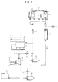
- Fig. 1 is a schematic view showing a constant temperature bath of warm-water circulating type used in an automatic analyzer.
- water in the constant temperature bath 1 (hereinafter referred to as “constant temperature bath water”) is held at a temperature of about 37°C with on/off control of a heater 3.
- the automatic analyzer further comprises a circulation pump 6 for circulating the constant temperature bath water, a reagent cooling unit 4 for keeping cool reagents and for cooling the circulating water when the water temperature rises excessively, a pipe 2 used for cooling a photometer lamp, a solenoid valve 10 for water supply, a trap 5 for removing air bubbles (hereinafter also referred to as an "air-bubble removing unit"), and a solenoid valve 9 for water drain. Further, a water supply pump 8 for supplying water to the constant temperature bath and a degassing unit 7 for removing oxygen dissolved in the supplied water are both connected to the constant temperature bath. The water to be supplied is stored in a water supply tank 13. A light emitted from the photometer lamp is illuminated to a mixture of the sample and the reagent in the reaction cell, and the light having passed through the mixture is measured by the photometer, thereby performing qualitative and quantitative analyses of a particular component in the sample.
- a first stage of a method for removing air bubbles can be performed at the time of exchanging the circulating water in the constant temperature bath.
- air bubbles contained in the water supplied to the constant temperature bath are removed when the water passes through the degassing unit 7.
- the air-bubble removing unit (trap) 5 is employed to remove those air bubbles.
- the trap 5 is in the form of a long tube and is able to store a certain amount of water without leaking. When the water including air bubbles enters the trap 5, the air bubbles accumulate in an upper portion of the trap 5 due to a difference in gravity between the air bubbles and the water. Then, only the water is returned to the circulation pump 6 from the bottom of the trap 5.
- the air bubbles accumulated in the trap 5 can be expelled out of the analyzer through the water drain solenoid valve 9.
- the air bubbles accumulated during the analyzer operation can be automatically expelled out to the exterior.
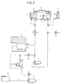
- Fig. 2 is a schematic view of another embodiment in which the trap 5 is provided in a sub-channel.
- the trap 5 is provided to locate at the same level as the water surface in the reaction tank 1, and the top of the trap 5 is left open to the atmosphere. With such an arrangement, air bubbles accumulated in the trap 5 is naturally released out of the analyzer.
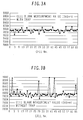
- Figs. 3A and 3B show comparative data of measurement results obtained with cell blank measurement (in which the measurement is performed by putting water, instead of a sample, in the reaction cell for calibration of values measured by the photometer) when the trap 5 is provided and when it is not provided.
- the vertical axis represents absorbance
- the horizontal axis represents the position number of each reaction cell (container) mounted to the reaction disk.
Landscapes
- Chemical & Material Sciences (AREA)
- Health & Medical Sciences (AREA)
- General Health & Medical Sciences (AREA)
- Life Sciences & Earth Sciences (AREA)
- Analytical Chemistry (AREA)
- Biochemistry (AREA)
- Physics & Mathematics (AREA)
- General Physics & Mathematics (AREA)
- Immunology (AREA)
- Pathology (AREA)
- Chemical Kinetics & Catalysis (AREA)
- Clinical Laboratory Science (AREA)
- Automatic Analysis And Handling Materials Therefor (AREA)
- Optical Measuring Cells (AREA)
Abstract
Description
Claims (8)
- An automatic analyzer comprising:a reaction cell (12) for mixing a sample and a reagent therein;a constant temperature bath (1) for holding water in which said reaction cell (12) is immersed;a suction pipe for sucking the water from said bath (1);a return pipe for returning the water to said bath (1);a pump (6) disposed between said suction and return pipes and circulating the water;a heater (3) for heating the water circulated in said bath (1) by said pump (6); andan air-bubble removing unit (5) disposed between said suction and return pipes, having a water-tight structure to hold the bath water therein, and removing air bubbles based on difference in gravity between the water and the air bubbles.
- The analyzer of Claim 1, wherein the position where said suction pipe is connected to said air-bubble removing unit (5) is higher than the position where said return pipe is connected to said air-bubble removing unit (5).
- The analyzer of Claim 2, wherein said air-bubble removing unit (5) is provided with an air bleeding pipe for expelling air bubbles accumulated in said air-bubble removing unit (5) to the exterior.
- The analyzer of Claim 2, wherein said air-bubble removing unit (5) has its top open to atmosphere.
- The analyzer of Claim 3, wherein a valve (9) for draining the water from said bath (1) to the exterior is the same as an air bleeding valve provided on said air-bubble removing unit (5).
- The analyzer of Claim 5, further comprising a constant-temperature-bath water injecting valve disposed between said suction and return pipes and injecting water into said bath (1).
- The analyzer of Claim 6, further comprising a control mechanism for, when the bath water is injected into said bath (1) by opening said water injecting valve, controlling said valve to be opened and closed such that the bath water is injected while said valve (9) provided on said air-bubble removing unit (5) is opened to drain the bath water.
- The analyzer of Claim 7, wherein said control mechanism is so programmed as to automatically operate in accordance with a predetermined schedule.
Applications Claiming Priority (2)
| Application Number | Priority Date | Filing Date | Title |
|---|---|---|---|
| JP2003421781A JP4185859B2 (en) | 2003-12-19 | 2003-12-19 | Automatic analyzer |
| JP2003421781 | 2003-12-19 |
Publications (3)
| Publication Number | Publication Date |
|---|---|
| EP1544601A2 true EP1544601A2 (en) | 2005-06-22 |
| EP1544601A3 EP1544601A3 (en) | 2006-05-10 |
| EP1544601B1 EP1544601B1 (en) | 2008-01-30 |
Family
ID=34510671
Family Applications (1)
| Application Number | Title | Priority Date | Filing Date |
|---|---|---|---|
| EP04029582A Expired - Lifetime EP1544601B1 (en) | 2003-12-19 | 2004-12-14 | Air bubbles removing system in an automatic analyzer |
Country Status (5)
| Country | Link |
|---|---|
| US (1) | US7459123B2 (en) |
| EP (1) | EP1544601B1 (en) |
| JP (1) | JP4185859B2 (en) |
| CN (1) | CN1308682C (en) |
| DE (1) | DE602004011592T2 (en) |
Cited By (4)
| Publication number | Priority date | Publication date | Assignee | Title |
|---|---|---|---|---|
| WO2008080076A3 (en) * | 2006-12-21 | 2008-08-21 | Johnson & Johnson Vision Care | Carousel having liquid filled cells for optical testing of ophthalmic lenses |
| EP2096441A3 (en) * | 2008-02-28 | 2010-11-17 | Hitachi High-Technologies Corporation | Automatic analyzer |
| CN101982779A (en) * | 2010-09-17 | 2011-03-02 | 济南齐力医疗器械有限公司 | Automatic sampling mechanism of analytical instrument |
| CN102830221A (en) * | 2012-08-31 | 2012-12-19 | 深圳市尚荣医疗股份有限公司 | Mixing device of automatic biochemical analyzer |
Families Citing this family (13)
| Publication number | Priority date | Publication date | Assignee | Title |
|---|---|---|---|---|
| EP2061599A4 (en) * | 2005-08-24 | 2014-01-22 | Telechemistry Oy | A method of testing a liquid sample, a test unit, and an automized system of a plurality of test units |
| JP2007292494A (en) * | 2006-04-21 | 2007-11-08 | Olympus Corp | Reaction vessel |
| JP4865633B2 (en) * | 2007-05-14 | 2012-02-01 | アサヒビール株式会社 | Wort transport system |
| JP5026994B2 (en) * | 2008-01-17 | 2012-09-19 | 株式会社日立ハイテクノロジーズ | Automatic analyzer |
| JP2010048695A (en) * | 2008-08-22 | 2010-03-04 | Olympus Corp | Autoanalyzer and method for stabilizing thermostatic chamber |
| CN103785314B (en) * | 2014-03-04 | 2016-05-11 | 厦门大学 | A kind of blender and flow type photometric detection automated analysis instrument |
| EP3163305B1 (en) | 2014-06-26 | 2021-11-10 | Hitachi High-Tech Corporation | Automatic analytical apparatus |
| CN105784600A (en) * | 2014-12-17 | 2016-07-20 | 浙江微兰环境科技有限公司 | Spectral absorption water quality monitoring apparatus |
| CN106732856A (en) * | 2016-12-27 | 2017-05-31 | 钦州市明大检测认证技术有限公司 | Thermostat water bath |
| CN106492901A (en) * | 2016-12-27 | 2017-03-15 | 钦州市明大检测认证技术有限公司 | Water-bath with clamping device |
| WO2021042319A1 (en) * | 2019-09-05 | 2021-03-11 | 深圳迈瑞生物医疗电子股份有限公司 | Analysis method for blood cell analyzer, and blood cell analyzer |
| CN117716240A (en) * | 2021-08-27 | 2024-03-15 | 株式会社日立高新技术 | Automatic analysis device |
| EP4431946A4 (en) * | 2021-11-09 | 2025-09-10 | Dainippon Ink & Chemicals | AUTOMATIC ANALYSIS DEVICE AND AUTOMATIC ANALYSIS METHOD |
Family Cites Families (19)
| Publication number | Priority date | Publication date | Assignee | Title |
|---|---|---|---|---|
| FR2026808A1 (en) * | 1968-12-21 | 1970-09-18 | Olympus Optical Co | |
| US4209131A (en) * | 1978-05-12 | 1980-06-24 | Motorola, Inc. | Computer-controlled irrigation system |
| JPS57171267A (en) * | 1981-04-15 | 1982-10-21 | Olympus Optical Co Ltd | Apparatus for automatic analysis |
| JPS57208433A (en) * | 1981-06-19 | 1982-12-21 | Toshiba Corp | Solution feeder |
| JPS5874161A (en) | 1981-10-28 | 1983-05-04 | Toshiba Corp | Low temperature melt-spraying device |
| JPS5874161U (en) * | 1981-11-16 | 1983-05-19 | 株式会社日立製作所 | Analyzer with constant temperature bath |
| DE3365508D1 (en) * | 1982-02-13 | 1986-10-02 | Toshiba Kk | Automatic chemical analyzer |
| JPS59182368A (en) * | 1983-03-31 | 1984-10-17 | Hitachi Ltd | Dispensing mechanism of multi-item automatic analyzer |
| JPS6385334A (en) * | 1986-09-30 | 1988-04-15 | Toshiba Corp | Thermostatic apparatus for analyser |
| JPS63165761A (en) * | 1986-12-27 | 1988-07-09 | Toshiba Corp | Automatic chemical analyzer |
| US4804519A (en) * | 1987-03-06 | 1989-02-14 | Thermo Jarrell Ash Corporation | Sample analysis apparatus |
| US4806135A (en) * | 1988-03-01 | 1989-02-21 | Siposs George G | Bubble trap for phase-separating gas bubbles from flowing liquids |
| US4869093A (en) * | 1988-05-18 | 1989-09-26 | Rutgers, The State University | Methods and apparatus for determining sorption isotherms |
| JPH03180749A (en) * | 1989-12-11 | 1991-08-06 | Hitachi Chem Co Ltd | Continuously measuring instrument for concentration of dissolved oxygen in high-temperature water or high-temperature aqueous solution |
| JPH10282108A (en) * | 1997-04-11 | 1998-10-23 | Hitachi Ltd | Automatic analyzer |
| JP3670851B2 (en) * | 1998-07-21 | 2005-07-13 | アクト・サイエンス株式会社 | Liquid chromatography pump |
| JP2001228160A (en) * | 2000-02-15 | 2001-08-24 | Hitachi Ltd | Automatic analyzer |
| JP2002296283A (en) * | 2001-04-02 | 2002-10-09 | Hitachi Ltd | Automatic analyzer |
| JP3883825B2 (en) * | 2001-07-03 | 2007-02-21 | 三洋電機株式会社 | Fluid transparency detection device, fluid transparency detection method, filtration device, and semiconductor device manufacturing method |
-
2003
- 2003-12-19 JP JP2003421781A patent/JP4185859B2/en not_active Expired - Lifetime
-
2004
- 2004-12-14 DE DE602004011592T patent/DE602004011592T2/en not_active Expired - Lifetime
- 2004-12-14 EP EP04029582A patent/EP1544601B1/en not_active Expired - Lifetime
- 2004-12-16 US US11/012,291 patent/US7459123B2/en active Active
- 2004-12-17 CN CNB2004101013594A patent/CN1308682C/en not_active Expired - Lifetime
Cited By (7)
| Publication number | Priority date | Publication date | Assignee | Title |
|---|---|---|---|---|
| WO2008080076A3 (en) * | 2006-12-21 | 2008-08-21 | Johnson & Johnson Vision Care | Carousel having liquid filled cells for optical testing of ophthalmic lenses |
| US7688453B2 (en) | 2006-12-21 | 2010-03-30 | Johnson & Johnson Vision Care, Inc. | Interferometry testing of lenses, and systems and devices for same |
| US8427636B2 (en) | 2006-12-21 | 2013-04-23 | Johnson & Johnson Vision Care, Inc | Cuvette for ophthalmic lens |
| EP2096441A3 (en) * | 2008-02-28 | 2010-11-17 | Hitachi High-Technologies Corporation | Automatic analyzer |
| CN101982779A (en) * | 2010-09-17 | 2011-03-02 | 济南齐力医疗器械有限公司 | Automatic sampling mechanism of analytical instrument |
| CN101982779B (en) * | 2010-09-17 | 2012-07-25 | 济南齐力医疗器械有限公司 | Automatic sampling mechanism of analytical instrument |
| CN102830221A (en) * | 2012-08-31 | 2012-12-19 | 深圳市尚荣医疗股份有限公司 | Mixing device of automatic biochemical analyzer |
Also Published As
| Publication number | Publication date |
|---|---|
| EP1544601B1 (en) | 2008-01-30 |
| JP4185859B2 (en) | 2008-11-26 |
| CN1308682C (en) | 2007-04-04 |
| US7459123B2 (en) | 2008-12-02 |
| CN1629635A (en) | 2005-06-22 |
| US20050135967A1 (en) | 2005-06-23 |
| EP1544601A3 (en) | 2006-05-10 |
| JP2005181087A (en) | 2005-07-07 |
| DE602004011592D1 (en) | 2008-03-20 |
| DE602004011592T2 (en) | 2009-02-19 |
Similar Documents
| Publication | Publication Date | Title |
|---|---|---|
| EP1544601B1 (en) | Air bubbles removing system in an automatic analyzer | |
| EP2096441A2 (en) | Automatic analyzer | |
| JP2834200B2 (en) | Liquid sample analyzer and analysis method | |
| US11237182B2 (en) | Automatic analyzer | |
| JPH0280937A (en) | Flow cell device | |
| US12151954B2 (en) | Automatic analyzer | |
| JP4251627B2 (en) | Chemical analyzer and dispensing method thereof | |
| CN1237243A (en) | Automatic chemistry analyzer with improved heated reaction cup assembly | |
| EP3985399B1 (en) | Automatic analysis device | |
| US20110104007A1 (en) | Automatic analyzing device | |
| JP7574421B2 (en) | Automatic analyzer and control method thereof | |
| JPH06130072A (en) | Automatic analyzer | |
| JP2007183240A (en) | Reaction cell for automatic analyzer and manufacturing method thereof, automatic analyzer equipped with the reaction cell, and analysis method | |
| CN212340984U (en) | Automatic urine iodine and water iodine analyzer | |
| JP6077075B2 (en) | Automatic analyzer | |
| JP4996959B2 (en) | Automatic analyzer with dispensing probe and control method thereof | |
| JP7229060B2 (en) | automatic analyzer | |
| CN116930294A (en) | Electrolyte analysis device, sample analyzer, and control method | |
| EP4597078A1 (en) | Automated analyzing device, and light source stabilization method for automated analyzing device | |
| JP7844177B2 (en) | automatic analyzer | |
| CN115656531B (en) | Integrated pesticide residue standardized rapid detection box and detection method | |
| JPH10282108A (en) | Automatic analyzer | |
| JPH0125423B2 (en) | ||
| JPH05149954A (en) | Automatic biochemical analytic device | |
| WO2025094189A1 (en) | Automated device and method for processing the microscope slides carrying specimens with reagent fluids. |
Legal Events
| Date | Code | Title | Description |
|---|---|---|---|
| PUAI | Public reference made under article 153(3) epc to a published international application that has entered the european phase |
Free format text: ORIGINAL CODE: 0009012 |
|
| AK | Designated contracting states |
Kind code of ref document: A2 Designated state(s): AT BE BG CH CY CZ DE DK EE ES FI FR GB GR HU IE IS IT LI LT LU MC NL PL PT RO SE SI SK TR |
|
| AX | Request for extension of the european patent |
Extension state: AL BA HR LV MK YU |
|
| PUAL | Search report despatched |
Free format text: ORIGINAL CODE: 0009013 |
|
| AK | Designated contracting states |
Kind code of ref document: A3 Designated state(s): AT BE BG CH CY CZ DE DK EE ES FI FR GB GR HU IE IS IT LI LT LU MC NL PL PT RO SE SI SK TR |
|
| AX | Request for extension of the european patent |
Extension state: AL BA HR LV MK YU |
|
| 17P | Request for examination filed |
Effective date: 20060331 |
|
| 17Q | First examination report despatched |
Effective date: 20060718 |
|
| AKX | Designation fees paid |
Designated state(s): DE FR |
|
| GRAP | Despatch of communication of intention to grant a patent |
Free format text: ORIGINAL CODE: EPIDOSNIGR1 |
|
| GRAS | Grant fee paid |
Free format text: ORIGINAL CODE: EPIDOSNIGR3 |
|
| GRAA | (expected) grant |
Free format text: ORIGINAL CODE: 0009210 |
|
| AK | Designated contracting states |
Kind code of ref document: B1 Designated state(s): DE FR |
|
| REF | Corresponds to: |
Ref document number: 602004011592 Country of ref document: DE Date of ref document: 20080320 Kind code of ref document: P |
|
| ET | Fr: translation filed | ||
| PLBE | No opposition filed within time limit |
Free format text: ORIGINAL CODE: 0009261 |
|
| STAA | Information on the status of an ep patent application or granted ep patent |
Free format text: STATUS: NO OPPOSITION FILED WITHIN TIME LIMIT |
|
| 26N | No opposition filed |
Effective date: 20081031 |
|
| REG | Reference to a national code |
Ref country code: FR Ref legal event code: PLFP Year of fee payment: 12 |
|
| REG | Reference to a national code |
Ref country code: FR Ref legal event code: PLFP Year of fee payment: 13 |
|
| REG | Reference to a national code |
Ref country code: FR Ref legal event code: PLFP Year of fee payment: 14 |
|
| REG | Reference to a national code |
Ref country code: DE Ref legal event code: R082 Ref document number: 602004011592 Country of ref document: DE Representative=s name: STREHL SCHUEBEL-HOPF & PARTNER MBB PATENTANWAE, DE Ref country code: DE Ref legal event code: R081 Ref document number: 602004011592 Country of ref document: DE Owner name: HITACHI SCIENCE SYSTEMS LTD., HITACHINAKA, JP Free format text: FORMER OWNERS: HITACHI HIGH-TECHNOLOGIES CORPORATION, TOKYO, JP; HITACHI SCIENCE SYSTEMS LTD., HITACHINAKA, IBARAKI, JP Ref country code: DE Ref legal event code: R081 Ref document number: 602004011592 Country of ref document: DE Owner name: HITACHI HIGH-TECH CORPORATION, JP Free format text: FORMER OWNERS: HITACHI HIGH-TECHNOLOGIES CORPORATION, TOKYO, JP; HITACHI SCIENCE SYSTEMS LTD., HITACHINAKA, IBARAKI, JP |
|
| PGFP | Annual fee paid to national office [announced via postgrant information from national office to epo] |
Ref country code: FR Payment date: 20211109 Year of fee payment: 18 |
|
| PG25 | Lapsed in a contracting state [announced via postgrant information from national office to epo] |
Ref country code: FR Free format text: LAPSE BECAUSE OF NON-PAYMENT OF DUE FEES Effective date: 20221231 |
|
| PGFP | Annual fee paid to national office [announced via postgrant information from national office to epo] |
Ref country code: DE Payment date: 20231031 Year of fee payment: 20 |
|
| REG | Reference to a national code |
Ref country code: DE Ref legal event code: R071 Ref document number: 602004011592 Country of ref document: DE |