EP1544472B1 - Rohrventilator - Google Patents
Rohrventilator Download PDFInfo
- Publication number
- EP1544472B1 EP1544472B1 EP04029400.1A EP04029400A EP1544472B1 EP 1544472 B1 EP1544472 B1 EP 1544472B1 EP 04029400 A EP04029400 A EP 04029400A EP 1544472 B1 EP1544472 B1 EP 1544472B1
- Authority
- EP
- European Patent Office
- Prior art keywords
- fan according
- impeller
- tube fan
- blades
- guiding device
- Prior art date
- Legal status (The legal status is an assumption and is not a legal conclusion. Google has not performed a legal analysis and makes no representation as to the accuracy of the status listed.)
- Expired - Lifetime
Links
- 239000011358 absorbing material Substances 0.000 claims 2
- XAGFODPZIPBFFR-UHFFFAOYSA-N aluminium Chemical compound [Al] XAGFODPZIPBFFR-UHFFFAOYSA-N 0.000 claims 2
- 229910052782 aluminium Inorganic materials 0.000 claims 2
- 239000004411 aluminium Substances 0.000 claims 2
- 230000007423 decrease Effects 0.000 description 3
- 239000007789 gas Substances 0.000 description 3
- 238000006243 chemical reaction Methods 0.000 description 2
- 238000010276 construction Methods 0.000 description 2
- 239000011324 bead Substances 0.000 description 1
- 230000003247 decreasing effect Effects 0.000 description 1
- 238000011161 development Methods 0.000 description 1
- 230000018109 developmental process Effects 0.000 description 1
- 238000009422 external insulation Methods 0.000 description 1
- 239000011810 insulating material Substances 0.000 description 1
- 239000000463 material Substances 0.000 description 1
- 239000002184 metal Substances 0.000 description 1
- 238000005457 optimization Methods 0.000 description 1
- 238000007789 sealing Methods 0.000 description 1
- 230000003068 static effect Effects 0.000 description 1
Images

Classifications
-
- F—MECHANICAL ENGINEERING; LIGHTING; HEATING; WEAPONS; BLASTING
- F04—POSITIVE - DISPLACEMENT MACHINES FOR LIQUIDS; PUMPS FOR LIQUIDS OR ELASTIC FLUIDS
- F04D—NON-POSITIVE-DISPLACEMENT PUMPS
- F04D29/00—Details, component parts, or accessories
- F04D29/40—Casings; Connections of working fluid
- F04D29/52—Casings; Connections of working fluid for axial pumps
- F04D29/54—Fluid-guiding means, e.g. diffusers
- F04D29/541—Specially adapted for elastic fluid pumps
- F04D29/542—Bladed diffusers
-
- F—MECHANICAL ENGINEERING; LIGHTING; HEATING; WEAPONS; BLASTING
- F04—POSITIVE - DISPLACEMENT MACHINES FOR LIQUIDS; PUMPS FOR LIQUIDS OR ELASTIC FLUIDS
- F04D—NON-POSITIVE-DISPLACEMENT PUMPS
- F04D17/00—Radial-flow pumps, e.g. centrifugal pumps; Helico-centrifugal pumps
- F04D17/06—Helico-centrifugal pumps
-
- F—MECHANICAL ENGINEERING; LIGHTING; HEATING; WEAPONS; BLASTING
- F04—POSITIVE - DISPLACEMENT MACHINES FOR LIQUIDS; PUMPS FOR LIQUIDS OR ELASTIC FLUIDS
- F04D—NON-POSITIVE-DISPLACEMENT PUMPS
- F04D17/00—Radial-flow pumps, e.g. centrifugal pumps; Helico-centrifugal pumps
- F04D17/08—Centrifugal pumps
- F04D17/16—Centrifugal pumps for displacing without appreciable compression
- F04D17/165—Axial entry and discharge
-
- F—MECHANICAL ENGINEERING; LIGHTING; HEATING; WEAPONS; BLASTING
- F04—POSITIVE - DISPLACEMENT MACHINES FOR LIQUIDS; PUMPS FOR LIQUIDS OR ELASTIC FLUIDS
- F04D—NON-POSITIVE-DISPLACEMENT PUMPS
- F04D29/00—Details, component parts, or accessories
- F04D29/26—Rotors specially for elastic fluids
- F04D29/28—Rotors specially for elastic fluids for centrifugal or helico-centrifugal pumps for radial-flow or helico-centrifugal pumps
- F04D29/284—Rotors specially for elastic fluids for centrifugal or helico-centrifugal pumps for radial-flow or helico-centrifugal pumps for compressors
-
- F—MECHANICAL ENGINEERING; LIGHTING; HEATING; WEAPONS; BLASTING
- F04—POSITIVE - DISPLACEMENT MACHINES FOR LIQUIDS; PUMPS FOR LIQUIDS OR ELASTIC FLUIDS
- F04D—NON-POSITIVE-DISPLACEMENT PUMPS
- F04D29/00—Details, component parts, or accessories
- F04D29/66—Combating cavitation, whirls, noise, vibration or the like; Balancing
- F04D29/661—Combating cavitation, whirls, noise, vibration or the like; Balancing especially adapted for elastic fluid pumps
- F04D29/663—Sound attenuation
- F04D29/664—Sound attenuation by means of sound absorbing material
Definitions
- the invention relates to a fan with rotationally symmetrical housing for conveying air or other gases.
- Such fans are used in particular at the beginning, inside or at the end of pipelines. They are therefore often called tube fans.
- the field of application of the pipe ventilator according to the invention is not limited to use in piping systems.
- tube fans There are a number of different constructions of tube fans known.
- a first type of tube fans see, eg US 2003/0206800
- a second type of tube fans also has a bulbous housing.
- Diagonallaufrad a radially aligned diffuser connects.
- a Diagonallaufrad consisting of a support plate and a number of two-dimensionally curved, non-profiled sheet metal blades, and an axially adjacent diffuser has a third type of tube fans.
- the present invention seeks to provide a tubular fan with a very high efficiency and a high power density with a low overall noise.
- the tube fan according to the invention is characterized in that the diaphragm fan, consisting of cover plate, support plate and a number of blades attached to these two discs in the axial direction, a nozzle is connected downstream.
- the impeller blades and the guide vanes of the pipe ventilator according to the invention are curved in three dimensions and profiled in order to be able to take account of the different angles of incidence along the leading edges of the blades.
- the profiling is a substantially continuous increase of the blade cross-section up to a maximum and an adjoining substantially continuous decrease of the blade cross-section.
- the pipe ventilator according to the invention in particular does not need to have an inlet nozzle when the impeller cover plate widens like a nozzle.
- the seal between suction and pressure chamber can be made at the impeller outlet.
- a diffuser can be connected downstream of the distributor.
- the housing of the tube fan can be ideally made of a one-piece cylindrical tube.
- the tube fan 10 has an outer housing shell 12, which encloses a circular cylindrical, straight cylinder interior.
- a left and right flange 18, 20 are fixedly mounted externally on the housing shell 12, which project beyond the housing jacket 12 in the axial direction (axis 22).
- flanges 18, 20 can be connected at both ends of the housing shell 12 and thus on the pipe fan 10 each have a pipe 24, 26 of a pipe not shown.
- the tube fan 10 can thus be installed between the tubes 24, 26.
- the outer diameter 28 and 30 of the tubes 24 and 26 thus corresponds in the present example also the Außi tomesser 32 of the housing shell 12.
- the tubes 24, 26 could each have a different diameter from the outer diameter and are connected via a corresponding pipe adapter to the pipe fan.
- the pipe ventilator 10 has a diagonal impeller 40, which is present on the input side of this fan 10. Downstream of this Diagonallaufrades 40 is a guide 42 and then the same still formed a diffuser 44 following the diagonal impeller 40 within the tubular fan 10.
- the gaseous flow medium forced through the tube fan 10 by means of the diagonal impeller 40 flows around a central interior of the tube ventilator 10, which is delimited outwardly by the carrier disc 50 of the tube ventilator 10 and an intermediate casing 52 which adjoins the carrier disc 50 in a streamlined manner.
- the carrier disc 50 curves at the end in the axial direction, so that it abuts aerodynamically on the aligned in the axial direction intermediate jacket 52.
- the flow medium thus flows radially outward on the support disk 50 and past the intermediate casing 52.
- the Diagonallaufradrad 40 has circumferentially distributed blades 54 which are fixed with its one side to the support plate 50 and with its opposite other side to a cover plate 56.
- the blades 54 are profiled cross-section in the present case and also wound.
- its inflow-side leading edge 55 which is aligned approximately perpendicular to the flow direction (arrow 58) of the flowing flow medium, is provided with a fillet.
- the outflow-side outlet edge 60 which is likewise oriented approximately perpendicular to the diagonal flow (arrow 62) leaving the downstream side, has the shape of a point.
- the cross-section of the individual blades 54 is not constant in the region between the support disk 50 and the cover disk 56, but varies in size.
- each blade 54 decreases from the region of the cover disk 56 to the region of the support disk 50, so that the blade 54 is the least curved in the region of the support disk 50 and the most curved in the region of the cover disk 56.
- the decrease in curvature could also be opposite, with the strongest curvature in the region of the support disk. This depends on the different flow conditions along the blades 54 between their respective connection area on the cover disk 56 and on the support disk 50 off.
- the leading edge 55 and the trailing edge 60 may be present instead of just curved.
- the curvature of all vanes 54 of the diagonal impeller 40 may have a so-called forward curvature or reverse curvature. Which curvature is selected depends on whether or not the velocity energy present there is still to be converted into pressure downstream of the impeller. With forwardly curved blades, a greater deflection of the flow medium in the region of the blades is achieved compared to backward curved blades, which leads to a greater energy conversion with the requirement that the velocity energy is still downstream, for example by means of the diffuser 44 in pressure.
- the cover plate 56 runs on the inflow side with a radially oriented end wall 61, which is very narrow in the present case.
- the radially inwardly bulged starting portion 56.1 of the cover plate 56 to the end wall 61 runs relatively pointed.
- the downstream end portion 56.2 of the cover plate 56 has a much stronger downstream tip, as it has the initial region 56.1.
- an angled annular gap 68 is present in the present case, which can not be avoided in principle due to the stationary housing wall 12 and the rotating Diagonallaufrades 40.
- this angled annular gap 68 is a sealing element 70, the distance in a engages in the cover plate 56 angularly shaped annular groove 72.
- This angled annular gap 68 represents a flow labyrinth and prevents or impedes that the gas flow leaving the blades 54 flows backwards through the annular gap 68 into the intermediate space 74 which is present between the cover disk 56 and the housing jacket 12. The stronger such a return flow is formed, the lower the efficiency of the tube fan 10.
- the flow leaving the diagonal impeller 40 then flows through the region of the guide device 42.
- guide vanes 80 are arranged between the intermediate casing 52 and the housing wall. In the present case, these guide vanes 80 are more curved in their outer region 80.1, which faces the housing shell 12, than in its inner region 80.2, which faces the intermediate casing 52. In this way, the gas flow leaving the diagonal impeller 40 in a helical, diagonal direction is deflected in an axial flow direction (arrow 84).
- the guide vanes 80 are wound three-dimensionally and formed profiled.
- the outer side of the wall section 52.1 of the intermediate jacket 52 is planar in the area of the guide vanes 80. However, it is also possible to increase the distance between the intermediate jacket 52 and the housing shell 12 in the flow direction by the intermediate jacket 52 downstream has a decreasing diameter.
- a transverse wall 86 is fixed to the intermediate casing 52, in the region of the blades 80, to which the motor 88 driving the diagonal impeller 40 is fastened.
- the diffuser 44 is formed downstream thereof.
- This diffuser 44 is structurally realized by a flow-ring channel which enlarges on the outflow side between the housing jacket 12 and the intermediate jacket 52.
- the intermediate jacket 52 is inclined in the region of the diffuser 44 with an angle 90 which is greater than zero degrees and less than 30 degrees, against the axial direction 22.1.
- this wall section 52.2 is also planar, as is the wall section 52.1 in the region of the guide device 42.
- the wall portion 52.2 may be bent in the axial direction, so that the flow ring channel widens in cross-section reinforced in the flow direction.
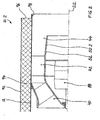
- the in Fig. 2 illustrated tube fan 10.2 differs from the tube fan 10 in principle in particular in that its housing shell 12 is surrounded by an insulating sleeve 92 performing insulating material 94.
- This insulating sleeve 92 is annularly bordered by a respective end Z-shaped tubular frame 96.
- This frame 96 surrounds the front edge of the housing shell 12 with a bead 98.
- the annular shape of the housing shell 12 and thus the tube fan 10.2 - the same is true for the tube fan 10 - makes attaching an external insulation structurally very simple. Thus, no bulged wall portions of the tube fan are present, as is the case in the prior art, which can disguise only relatively complex with material outside.
- the defined by the intermediate sheath 52 sleeve is designed to sound permeable and thereby acts sound-absorbing.
- the intermediate jacket is formed at least in the wall portion 52.2 as a perforated plate.
Landscapes
- Engineering & Computer Science (AREA)
- Mechanical Engineering (AREA)
- General Engineering & Computer Science (AREA)
- Structures Of Non-Positive Displacement Pumps (AREA)
Description
- Die Erfindung betrifft einen Ventilator mit rotationssymmetrischem Gehäuse zum Fördern von Luft oder anderen Gasen. Derartige Ventilatoren werden insbesondere am Anfang, innerhalb oder am Ende von Rohrleitungen eingesetzt. Sie werden daher häufig Rohrventilatoren genannt. Das Einsatzgebiet des erfindungsgemäßen Rohrventilators beschränkt sich allerdings nicht nur auf die Verwendung in Rohrleitungssystemen.
- Es sind eine Reihe unterschiedlicher Konstruktionen von Rohrventilatoren bekannt. Bei einer ersten Art von Rohrventilatoren (siehe z.B.
US 2003/0206800 ) ist ein rückwärts gekrümmtes Radiallaufrad in einem zwiebelförmigen Gehäuse untergebracht. Eine zweite Art von Rohrventilatoren besitzt ebenfalls ein zwiebelförmiges Gehäuse. An das aus einer Deckscheibe, einer Tragscheibe und einer Anzahl zweidimensional gekrümmter, nicht profilierter Schaufeln bestehende Diagonallaufrad schließt sich ein radial ausgerichteter Leitapparat an. Ein Diagonallaufrad, bestehend aus einer Tragscheibe und einer Anzahl zweidimensional gekrümmter, nicht profilierter Blechschaufeln, und einem sich axial anschließenden Leitapparat besitzt eine dritte Art von Rohrventilatoren. - Ausgehend von diesem vorbekannten Stand der Technik liegt der Erfindung die Aufgabe zugrunde, einen Rohrventilator mit einem sehr hohen Wirkungsgrad und einer hohen Leistungsdichte bei insgesamt niedrigem Geräusch bereitzustellen.
- Die Erfindung ist durch die Merkmale des Hauptanspruches gegeben. Sinnvolle Weiterbildungen der Erfindung sind Gegenstand von sich an den Hauptanspruch anschließenden weiteren Ansprüchen.
- Der erfindungsgemäße Rohrventilator zeichnet sich dadurch aus, dass dem Diagonalventilator, bestehend aus Deckscheibe, Tragscheibe und einer Anzahl von an diesen beiden Scheiben befestigter Schaufeln in axialer Richtung ein Leitapparat nachgeschaltet ist. Eine Reihe von darauf aufbauender Optimierungen sind Gegenstand von sich an den Hauptanspruch anschließenden weiteren Ansprüchen. Die Laufradschaufeln und die Leitschaufeln des erfindungsgemäßen Rohrventilators sind dreidimensional gekrümmt und profiliert, um den unterschiedlichen Anströmwinkeln entlang der Eintrittskanten der Schaufeln jeweils Rechnung tragen zu können.
- Die Profilierung ist eine im Wesentlichen stetige Zunahme des Schaufelquerschnittes bis zu einem Maximum und eine daran anschließende im Wesentlichen stetige Abnahme des Schaufelquerschnittes.
- Der erfindungsgemäße Rohrventilator braucht insbesondere dann keine Einströmdüse zu besitzen, wenn die Laufrad-Deckscheibe sich düsenförmig erweitert. Die Abdichtung zwischen Saug- und Druckraum kann am Laufradaustritt erfolgen. Zur weiteren Steigerung der Druckumsetzung von dynamischem in statischen Druck kann dem Leitapparat ein Diffusor nachgeschaltet werden. Das Gehäuse des Rohrventilators kann idealerweise aus einem einteiligen zylindrischen Rohr hergestellt sein.
- Weitere Vorteile und Merkmale der Erfindung sind den in den Ansprüchen ferner angegebenen Merkmalen sowie den nachstehenden Ausführungsbeispielen zu entnehmen.
- Die Erfindung wird im Folgenden anhand der in der Zeichnung dargestellten Ausführungsbeispiele näher beschrieben und,erläutert. Es zeigen:
- Fig. 1
- eine halbe Schnittdarstellung eines Rohrventilators nach der Erfindung,
- Fig. 2
- eine Darstellung ähnlich der von
Fig. 1 von einem außen gedämmten Rohrventilator nach der Erfindung. - Der Rohrventilator 10 besitzt einen äußeren Gehäusemantel 12, der einen kreiszylindrischen, geraden Zylinderinnenraum umschließt. An seiner linken und rechten jeweils endseitigen Stirnwand 14, 16 sind außen an dem Gehäusemantel 12 jeweils ein linker und rechter Flansch 18, 20 fest angebracht, die den Gehäusemantel 12 in axialer Richtung (Achse 22) überragen. Mittels dieser Flansche 18, 20 kann an beiden Enden des Gehäusemantels 12 und damit am Rohrventilator 10 jeweils ein Rohr 24, 26 einer nicht weiter dargestellten Rohrleitung angeschlossen werden. Der Rohrventilator 10 kann also zwischen den Rohren 24, 26 eingebaut werden. Der Außendurchmesser 28 beziehungsweise 30 der Rohre 24 beziehungsweise 26 entspricht damit im vorliegenden Beispielsfall auch dem Außeridurchmesser 32 des Gehäusemantels 12. Die Rohre 24, 26 könnten auch jeweils einen vom Durchmesser 32 abweichenden Außendurchmesser besitzen und über einen entsprechenden Rohradapter an den Rohrventilator angeschlossen werden.
- Der Rohrventilator 10 besitzt ein Diagonallaufrad 40, das eingangsseitig dieses Ventilators 10 vorhanden ist. Abströmseitig dieses Diagonallaufrades 40 ist eine Leiteinrichtung 42 und anschließend derselben noch ein Diffusor 44 im Anschluss an das Diagonallaufrad 40 innerhalb des Rohrventilators 10 ausgebildet.
- Das mittels des Diagonallaufrades 40 durch den Rohrventilator 10 hindurchgedrückte gasförmige Strömungsmedium umströmt einen zentralen Innenraum des Rohrventilators 10, der nach außen abgegrenzt wird durch die Tragscheibe 50 des Rohrventilators 10 und einen sich an die Tragscheibe 50 strömungsgünstig anschließenden Zwischenmantel 52. Die Tragscheibe 50 krümmt sich endseitig in axialer Richtung, so dass sie strömungsgünstig an den in axialer Richtung ausgerichteten Zwischenmantel 52 anstößt. Das Strömungsmedium strömt damit radial außen an der Tragscheibe 50 und an dem Zwischenmantel 52 vorbei.
- Das Diagonallaufrad 40 besitzt umfangsmäßig verteilte Schaufeln 54, die mit ihrer einen Seite an der Tragscheibe 50 und mit ihrer gegenüberliegenden anderen Seite an einer Deckscheibe 56 befestigt sind. Die Schaufeln 54 sind im vorliegenden Fall querschnittsmäßig profiliert und außerdem verwunden. So ist ihre anströmseitige Eintrittskante 55, die in etwa senkrecht zur Strömungsrichtung (Pfeil 58) des sie anströmenden Strömungsmediums ausgerichtet ist, mit einer Ausrundung versehen. Die abströmseitige Austrittskante 60, die ebenfalls etwa senkrecht zur sie abströmseitig verlassenden Diagonalströmung (Pfeil 62) ausgerichtet ist, besitzt die Form einer Spitze. Der Querschnitt der einzelnen Schaufeln 54 ist im Bereich zwischen der Tragscheibe 50 und der Deckscheibe 56 nicht konstant, sondern unterschiedlich groß. Auch nimmt die Krümmung jeder Schaufel 54 vom Bereich der Deckscheibe 56 zum Bereich der Tragscheibe 50 ab, so dass die Schaufel 54 im Bereich der Tragscheibe 50 am wenigsten und im Bereich der Deckscheibe 56 am stärksten gekrümmt ist. Die Krümmungsabnahme könnte beispielsweise aber auch gegenläufig sein, mit der stärksten Krümmung im Bereich der Tragscheibe. Dies hängt von den unterschiedlichen Strömungsverhältnissen längs der Schaufeln 54 zwischen ihrem jeweiligen Anschlussbereich an der Deckscheibe 56 und an der Tragscheibe 50 ab. Die Eintrittskante 55 und die Austrittskante 60 können statt gerade auch gewölbt vorhanden sein.
- Die Krümmung aller Schaufeln 54 des Diagonallaufrades 40 können eine sogenannte Vorwärtskrümmung oder Rückwärtskrümmung aufweisen. Welche Krümmung gewählt wird, hängt davon ab, ob abströmseitig des Laufrades die dort vorhandene Geschwindigkeitsenergie noch in Druck umgesetzt werden soll oder nicht. Mit vorwärts gekrümmten Schaufeln wird im Vergleich zu rückwärts gekrümmten Schaufeln eine stärkere Umlenkung des Strömungsmediums im Bereich der Schaufeln erreicht, was zu einer größeren Energieumsetzung führt mit dem Erfordernis, dass die Geschwindigkeitsenergie noch abströmseitig beispielsweise mittels des Diffusors 44 in Druck umgesetzt wird.
- Die Deckscheibe 56 läuft anströmseitig mit einer radial ausgerichteten Stirnwand 61 aus, die im vorliegenden Fall sehr schmal ist. So läuft der nach radial innen ausgewölbte Anfangsbereich 56.1 der Deckscheibe 56 zur Stirnwand 61 relativ spitz aus.
- Der abströmseitige Endbereich 56.2 der Deckscheibe 56 besitzt eine wesentlich stärkere abströmseitige Spitze, als sie der Anfangsbereich 56.1 aufweist.
- Zwischen dem Endbereich 56.2 und dem Gehäusemantel 12 ist ein im vorliegenden Fall abgewinkelter Ringspalt 68 vorhanden, der sich prinzipiell nicht vermeiden lässt infolge der stationären Gehäusewand 12 und des rotierenden Diagonallaufrades 40. In diesem abgewinkelten Ringspalt 68 liegt ein Dichtungselement 70, das mit Abstand in eine in der Deckscheibe 56 winkelförmig eingeformten Ringnut 72 eingreift. Dieser abgewinkelte Ringspalt 68 stellt ein Strömungslabyrinth dar und verhindert beziehungsweise erschwert, dass die die Schaufeln 54 abströmseitig verlassende Gasströmung rückwärts durch den Ringspalt 68 wieder in den Zwischenraum 74 einströmt, der zwischen der Deckscheibe 56 und dem Gehäusemantel 12 vorhanden ist. Je stärker eine solche Rückströmung sich ausgebildet, umso niedriger wird der Wirkungsgrad des Rohrventilators 10.
- Die das Diagonallaufrad 40 verlassende Strömung durchströmt anschließend den Bereich der Leiteinrichtung 42. In diesem Rohrabschnitt des Rohrventilators 10 sind zwischen dem Zwischenmantel 52 und der Gehäusewand Leitschaufeln 80 angeordnet. Im vorliegenden Fall sind diese Leitschaufeln 80 in ihrem äußeren Bereich 80.1, der dem Gehäusemantel 12 zugewandt ist, stärker gekrümmt als in ihrem inneren Bereich 80.2, der dem Zwischenmantel 52 zugewandt ist. Auf diese Weise wird die in schraubenförmiger, diagonaler Richtung das Diagonallaufrad 40 verlassende Gasströmung in eine axiale Strömungsrichtung (Pfeil 84) umgelenkt.
- Auch die Leitschaufeln 80 sind dreidimensional verwunden und profiliert ausgebildet.
- Die Außenseite des Wandabschnittes 52.1 des Zwischenmantels 52 ist im Bereich der Leitschaufeln 80 ebenflächig ausgebildet. Es ist allerdings auch möglich, den Abstand zwischen dem Zwischenmantel 52 und dem Gehäusemantel 12 in Strömungsrichtung sich vergrößern zu lassen, indem der Zwischenmantel 52 abströmseitig einen sich verkleinernden Durchmesser besitzt.
- Im vorliegenden Fall ist an dem Zwischenmantel 52, im Bereich der Schaufeln 80, eine Querwand 86 befestigt, an der der das Diagonallaufrad 40 antreibende Motor 88 befestigt ist.
- Im Anschluss an die Leiteinrichtung 42 ist abströmseitig derselben der Diffusor 44 ausgebildet. Dieser Diffusor 44 wird durch einen sich abströmseitig vergrößernden Strömungsringkanal zwischen dem Gehäusemantel 12 und dem Zwischenmantel 52 konstruktiv verwirklicht. So ist der Zwischenmantel 52 im Bereich des Diffusors 44 mit einem Winkel 90, der größer Null Grad und kleiner 30 Grad ist, gegen die axiale Richtung 22.1 geneigt. Im Bereich des Diffusors 44 ist dieser Wandabschnitt 52.2 ebenfalls ebenflächig so wie es auch der Wandabschnitt 52.1 im Bereich der Leiteinrichtung 42 ist. Allerdings ist es möglich, die beiden Wandabschnitte 52.1 und 52.2 nicht mit einem Knick 91 aneinanderstoßen zu lassen, sondern mit einer gleichmäßigen Krümmung zu versehen, um Querschnittssprünge in der Wandungskonstruktion der das Strömungsmedium begrenzenden Bauteile zu vermeiden. Auch kann der Wandabschnitt 52.2 in axialer Richtung gebogen sein, so dass der Strömungsringkanal sich in Strömungsrichtung querschnittsmäßig verstärkt aufweitet.
- Der in
Fig. 2 dargestellte Rohrventilator 10.2 unterscheidet sich vom Rohrventilator 10 prinzipiell insbesondere dadurch, dass sein Gehäusemantel 12 von einem eine Isolierungshülse 92 darstellenden Dämmmaterial 94 umgeben ist. Diese Isolierungshülse 92 wird von jeweils einer endseitigen Z-förmigen Rohrzarge 96 ringförmig eingefasst. Diese Zarge 96 umgreift mit einer Umbördelung 98 den Stirnrand des Gehäusemantels 12. Die kreisringförmige Form des Gehäusemantels 12 und damit des Rohrventilators 10.2 - Vergleichbares gilt auch für den Rohrventilator 10 - macht die Anbringung einer äußeren Isolierung konstruktiv sehr einfach. So sind keine ausgewölbten Wandbereiche des Rohrventilators vorhanden, so wie es im Stand der Technik der Fall ist, die sich nur relativ aufwändig mit Material außen verkleiden lassen. - Die durch den Zwischenmantel 52 definierte Hülse ist schalldurchlässig ausgebildet und wirkt dadurch schalldämpfend. Im vorliegenden Fall ist der Zwischenmantel zumindest im Wandabschnitt 52.2 als Lochblech ausgebildet.
Claims (16)
- Rohrventilator (10, 10.2) für gasförmige Medien,- mit einem mehrere Schaufeln (54) aufweisenden Diagonallaufrad (40), dessen Schaufel (54) an einer Tragscheibe (50) und an einer Deckscheibe (56) befestigt sind, und- mit einer sich abströmseitig an das Diagonallaufrad (40) anschließenden Leiteinrichtung (42) zur Druckerhöhung des Mediums, die sich in axialer Richtung (22.1) an das Diagonallaufrad (40) abschließt- dadurch gekennzeichnet, dass- die Schaufel (80) der Leiteinrichtung (42) dreidimensional verwunden sind.
- Rohrventilator nach einem der vorstehenden Ansprüche,
dadurch gekennzeichnet, dass- sich der Leiteinrichtung (42) ein abströmseitig allmählich sich vergrößernder Strömungskanal anschließt. - Rohrventilator nach einem der vorstehenden Ansprüche,
dadurch gekennzeichnet, dass- sein hohlzylindrisches Gehäuse einen Gehäusemantel (12) besitzt, der längs seiner Zylinderachse (22) konstante Querschnittsmaße aufweist. - Rohrventilator nach einem der vorstehenden Ansprüche,
dadurch gekennzeichnet, dass- die Schaufeln (54) des Laufrades (40) profiliert sind. - Rohrventilator nach einem der vorstehenden Ansprüche,
dadurch gekennzeichnet, dass- die Schaufeln (80) der Leiteinrichtung (42) profiliert sind. - Rohrventilator nach einem der vorstehenden Ansprüche,
dadurch gekennzeichnet, dass- die Schaufeln (54) des Laufrades (40) dreidimensional verwunden sind. - Rohrventilator nach einem der vorstehenden Ansprüche,
dadurch gekennzeichnet, dass- zwischen der Deckscheibe (56) des Laufrades (40) und einem das Laufrad (40) enthaltenden Gehäuse (12) ein Ringspalt (68) vorhanden ist. - Rohrventilator nach Anspruch 7,
dadurch gekennzeichnet, dass- der Ringspalt (68) labyrinthartig ausgebildet ist. - Rohrventilator nach einem der vorstehenden Ansprüche,
dadurch gekennzeichnet, dass- das abströmseitige Ende (56.2) der Deckscheibe (56) des Laufrades (40) in etwa in axialer Richtung (22.1) ausgerichtet ist, so dass die Deckscheibe (56) eine allmähliche Krümmung in Richtung Leiteinrichtung (42) aufweist. - Rohrventilator nach einem der vorstehenden Ansprüche,
dadurch gekennzeichnet, dass- die Deckscheibe des Laufrades sich entgegen der Strömungsrichtung düsenartig aufweitet. - Rohrventilator nach einem der vorstehenden Ansprüche,
dadurch gekennzeichnet, dass- das abströmseitige Ende der Tragscheibe (50) des Laufrades (40) in etwa in axialer Richtung (22.1) ausgerichtet ist, so dass die Tragscheibe (50) am Laufradaustritt eine allmähliche Krümmung in Richtung Leiteinrichtung (42) aufweist. - Rohrventilator nach einem der vorstehenden Ansprüche,
dadurch gekennzeichnet, dass- der Gehäusemantel (12) von einem schallabsorbierenden Material (94) umgeben ist,- der Gehäusemantel (12) schalldurchlässig ist. - Rohrventilator nach Anspruch 12,
dadurch gekennzeichnet, dass- das schallabsorbierende Material (94) von einem weiteren Gehäusemantel (92) umgeben ist. - Rohrventilator nach einem der vorstehenden Ansprüche,
dadurch gekennzeichnet, dass- die Leiteinrichtung (42) aus Kunststoff oder Aluminium besteht. - Rohrventilator nach einem der vorstehenden Ansprüche, dadurch gekennzeichnet, dass- die Laufradschaufeln (54) aus Kunststoff oder Aluminium bestehen.
- Rohrventilator nach einem der vorstehenden Ansprüche,
dadurch gekennzeichnet, dass- die Leiteinrichtung (42) mit dem sich anschließenden, sich vergrößernden Strömungskanal (Diffusor 44) und mit der Aufhängung für den motorischen Antrieb (88) aus einem Teil gefertigt ist.
Applications Claiming Priority (2)
| Application Number | Priority Date | Filing Date | Title |
|---|---|---|---|
| DE20319749U DE20319749U1 (de) | 2003-12-18 | 2003-12-18 | Rohrventilator |
| DE20319749U | 2003-12-18 |
Publications (3)
| Publication Number | Publication Date |
|---|---|
| EP1544472A2 EP1544472A2 (de) | 2005-06-22 |
| EP1544472A3 EP1544472A3 (de) | 2006-09-13 |
| EP1544472B1 true EP1544472B1 (de) | 2014-01-22 |
Family
ID=33441949
Family Applications (1)
| Application Number | Title | Priority Date | Filing Date |
|---|---|---|---|
| EP04029400.1A Expired - Lifetime EP1544472B1 (de) | 2003-12-18 | 2004-12-11 | Rohrventilator |
Country Status (2)
| Country | Link |
|---|---|
| EP (1) | EP1544472B1 (de) |
| DE (1) | DE20319749U1 (de) |
Cited By (3)
| Publication number | Priority date | Publication date | Assignee | Title |
|---|---|---|---|---|
| EP3821132A1 (de) * | 2018-11-16 | 2021-05-19 | ebm-papst Mulfingen GmbH & Co. KG | Diagonalventilator mit optimiertem diagonallaufrad |
| US11473594B2 (en) | 2018-05-18 | 2022-10-18 | Dyson Technology Limited | Compressor |
| DE102022131246A1 (de) | 2022-11-25 | 2024-05-29 | Ebm-Papst Mulfingen Gmbh & Co. Kg | Lüfter |
Families Citing this family (9)
| Publication number | Priority date | Publication date | Assignee | Title |
|---|---|---|---|---|
| DE102009015104A1 (de) * | 2009-03-31 | 2010-10-14 | Behr Gmbh & Co. Kg | Axiallüfter, insbesondere für ein Kraftfahrzeug |
| DE102010032168A1 (de) | 2010-07-23 | 2012-01-26 | Ruck Ventilatoren Gmbh | Diagonal-Ventilator |
| DE102010047489A1 (de) | 2010-10-06 | 2012-04-12 | Ruck Ventilatoren Gmbh | Wandeinbaugebläse |
| US20140023491A1 (en) | 2012-07-17 | 2014-01-23 | Ruck Ventilatoren Gmbh | Diagonal fan |
| DE102012019419A1 (de) | 2012-10-04 | 2014-04-10 | Ruck Ventilatoren Gmbh | Diagonal-Ventilator |
| CN105402165A (zh) * | 2014-09-09 | 2016-03-16 | 苏州金莱克精密机械有限公司 | 吹风机 |
| DE102016215738A1 (de) | 2016-08-23 | 2018-03-01 | Siemens Aktiengesellschaft | Laufrad, Verfahren zur Fertigung |
| DE102018128792A1 (de) * | 2018-11-16 | 2020-05-20 | Ebm-Papst Mulfingen Gmbh & Co. Kg | Kompakter Diagonalventilator mit Nachleiteinrichtung |
| DE102018128791A1 (de) | 2018-11-16 | 2020-05-20 | Ebm-Papst Mulfingen Gmbh & Co. Kg | Diagonalventilator mit Nachleiteinrichtung |
Family Cites Families (5)
| Publication number | Priority date | Publication date | Assignee | Title |
|---|---|---|---|---|
| US3059833A (en) * | 1956-10-17 | 1962-10-23 | Remi A Benoit | Fans |
| GB849744A (en) * | 1958-01-30 | 1960-09-28 | Blackman Keith Ltd | Improvements in fans |
| US3191364A (en) * | 1962-05-28 | 1965-06-29 | American Air Filter Co | Centrifugal dust separator |
| DE4020236A1 (de) * | 1990-06-26 | 1992-01-02 | Keller Lufttechnik Gmbh & Co Kg | Innerhalb eines luftansaugkanals angeordnete radialventilatoreinheit |
| MXPA02012408A (es) * | 2000-06-15 | 2004-02-26 | Greenheck Fan Corp | Ventilador centrifugo en linea. |
-
2003
- 2003-12-18 DE DE20319749U patent/DE20319749U1/de not_active Expired - Lifetime
-
2004
- 2004-12-11 EP EP04029400.1A patent/EP1544472B1/de not_active Expired - Lifetime
Cited By (4)
| Publication number | Priority date | Publication date | Assignee | Title |
|---|---|---|---|---|
| US11473594B2 (en) | 2018-05-18 | 2022-10-18 | Dyson Technology Limited | Compressor |
| EP3821132A1 (de) * | 2018-11-16 | 2021-05-19 | ebm-papst Mulfingen GmbH & Co. KG | Diagonalventilator mit optimiertem diagonallaufrad |
| DE102022131246A1 (de) | 2022-11-25 | 2024-05-29 | Ebm-Papst Mulfingen Gmbh & Co. Kg | Lüfter |
| EP4375514A1 (de) | 2022-11-25 | 2024-05-29 | ebm-papst Mulfingen GmbH & Co. KG | Lüfter |
Also Published As
| Publication number | Publication date |
|---|---|
| EP1544472A3 (de) | 2006-09-13 |
| DE20319749U1 (de) | 2004-11-04 |
| EP1544472A2 (de) | 2005-06-22 |
Similar Documents
| Publication | Publication Date | Title |
|---|---|---|
| EP1608875B1 (de) | Radiallüfterrad, lüftereinheit und radiallüfteranordnung | |
| EP0802305B1 (de) | Abgasturbolader für eine Brennkraftmaschine | |
| EP1544472B1 (de) | Rohrventilator | |
| EP2076661B1 (de) | Axiallüfter zur förderung von kühlluft für eine kühlvorrichtung eines kraftfahrzeuges | |
| EP2410183A2 (de) | Diagonal-Ventilator | |
| EP3775565B1 (de) | Kompakter diagonalventilator mit nachleiteinrichtung | |
| EP2655891A1 (de) | Ventilatordiffusor mit kreisförmigem einlass und nicht rotationssymmetrischem auslass | |
| EP2140112A1 (de) | Diffusoranordnung | |
| DE724553C (de) | Ausbildung des Arbeitsraumes in einem Kreiselradverdichter, in dem das gefoerderte Gas aus dem Laufrad mit UEberschallgeschwindigkeit austritt | |
| EP3372838B1 (de) | Raumlufttechnische lüftungsanlage mit einer luftleitanordnung | |
| EP2716915A1 (de) | Gehäuse für einen Axialventilator | |
| DE102012106412A1 (de) | Diagonal-Laufrad für einen Diagonal-Ventilator sowie Diagonal-Ventilator | |
| DE3706772C2 (de) | ||
| EP3009682B1 (de) | Axialventilator mit aussen- und innendiffusor | |
| DE112009001754T5 (de) | Abgasdiffusor für Gasturbine | |
| EP1447568A2 (de) | Lauf- und Leiträder für Verdichter und Ventilatoren | |
| DE1428273C3 (de) | Flügelrad für einen geräuscharmen Axialventilator | |
| DE2600860C2 (de) | Schalldämpfer auf der Ansaugseite eines Verdichters mit mehreren Dämpfungselementen | |
| DE3028606A1 (de) | Zum einbau in rohrleitungen, kanaele oder kanalaehnliche gehaeuse bzw. in lueftungs- und klimageraete bestimmte ventilatoreinheit | |
| DE102012106411A1 (de) | Diagonal-Laufrad für einen Diagonal-Ventilator sowie Diagonal-Ventilator | |
| DE20303443U1 (de) | Radiallüfterrad | |
| DE102008053144A1 (de) | Lüfteranordnung und Gargerät | |
| DE102016123961A1 (de) | Radialgebläse | |
| DE1925172B2 (de) | Nachleitgitter eines axialverdichters, insbesondere eines ueberschall- axialverdichters | |
| DE20319741U1 (de) | Radial- oder Diagonal-Ventilator |
Legal Events
| Date | Code | Title | Description |
|---|---|---|---|
| PUAI | Public reference made under article 153(3) epc to a published international application that has entered the european phase |
Free format text: ORIGINAL CODE: 0009012 |
|
| AK | Designated contracting states |
Kind code of ref document: A2 Designated state(s): AT BE BG CH CY CZ DE DK EE ES FI FR GB GR HU IE IS IT LI LT LU MC NL PL PT RO SE SI SK TR |
|
| AX | Request for extension of the european patent |
Extension state: AL BA HR LV MK YU |
|
| PUAL | Search report despatched |
Free format text: ORIGINAL CODE: 0009013 |
|
| AK | Designated contracting states |
Kind code of ref document: A3 Designated state(s): AT BE BG CH CY CZ DE DK EE ES FI FR GB GR HU IE IS IT LI LT LU MC NL PL PT RO SE SI SK TR |
|
| AX | Request for extension of the european patent |
Extension state: AL BA HR LV MK YU |
|
| 17P | Request for examination filed |
Effective date: 20070127 |
|
| AKX | Designation fees paid |
Designated state(s): AT BE BG CH CY CZ DE DK EE ES FI FR GB GR HU IE IS IT LI LT LU MC NL PL PT RO SE SI SK TR |
|
| 17Q | First examination report despatched |
Effective date: 20071227 |
|
| GRAP | Despatch of communication of intention to grant a patent |
Free format text: ORIGINAL CODE: EPIDOSNIGR1 |
|
| INTG | Intention to grant announced |
Effective date: 20130621 |
|
| GRAS | Grant fee paid |
Free format text: ORIGINAL CODE: EPIDOSNIGR3 |
|
| GRAP | Despatch of communication of intention to grant a patent |
Free format text: ORIGINAL CODE: EPIDOSNIGR1 |
|
| INTG | Intention to grant announced |
Effective date: 20131113 |
|
| RAP1 | Party data changed (applicant data changed or rights of an application transferred) |
Owner name: RUCK VENTILATOREN GMBH |
|
| GRAA | (expected) grant |
Free format text: ORIGINAL CODE: 0009210 |
|
| AK | Designated contracting states |
Kind code of ref document: B1 Designated state(s): AT BE BG CH CY CZ DE DK EE ES FI FR GB GR HU IE IS IT LI LT LU MC NL PL PT RO SE SI SK TR |
|
| REG | Reference to a national code |
Ref country code: GB Ref legal event code: FG4D Free format text: NOT ENGLISH |
|
| REG | Reference to a national code |
Ref country code: CH Ref legal event code: EP |
|
| REG | Reference to a national code |
Ref country code: AT Ref legal event code: REF Ref document number: 650950 Country of ref document: AT Kind code of ref document: T Effective date: 20140215 |
|
| REG | Reference to a national code |
Ref country code: IE Ref legal event code: FG4D Free format text: LANGUAGE OF EP DOCUMENT: GERMAN |
|
| REG | Reference to a national code |
Ref country code: DE Ref legal event code: R096 Ref document number: 502004014508 Country of ref document: DE Effective date: 20140227 |
|
| REG | Reference to a national code |
Ref country code: NL Ref legal event code: VDEP Effective date: 20140122 |
|
| REG | Reference to a national code |
Ref country code: LT Ref legal event code: MG4D |
|
| PG25 | Lapsed in a contracting state [announced via postgrant information from national office to epo] |
Ref country code: IS Free format text: LAPSE BECAUSE OF FAILURE TO SUBMIT A TRANSLATION OF THE DESCRIPTION OR TO PAY THE FEE WITHIN THE PRESCRIBED TIME-LIMIT Effective date: 20140522 Ref country code: LT Free format text: LAPSE BECAUSE OF FAILURE TO SUBMIT A TRANSLATION OF THE DESCRIPTION OR TO PAY THE FEE WITHIN THE PRESCRIBED TIME-LIMIT Effective date: 20140122 |
|
| PG25 | Lapsed in a contracting state [announced via postgrant information from national office to epo] |
Ref country code: CY Free format text: LAPSE BECAUSE OF FAILURE TO SUBMIT A TRANSLATION OF THE DESCRIPTION OR TO PAY THE FEE WITHIN THE PRESCRIBED TIME-LIMIT Effective date: 20140122 Ref country code: SE Free format text: LAPSE BECAUSE OF FAILURE TO SUBMIT A TRANSLATION OF THE DESCRIPTION OR TO PAY THE FEE WITHIN THE PRESCRIBED TIME-LIMIT Effective date: 20140122 Ref country code: ES Free format text: LAPSE BECAUSE OF FAILURE TO SUBMIT A TRANSLATION OF THE DESCRIPTION OR TO PAY THE FEE WITHIN THE PRESCRIBED TIME-LIMIT Effective date: 20140122 Ref country code: PT Free format text: LAPSE BECAUSE OF FAILURE TO SUBMIT A TRANSLATION OF THE DESCRIPTION OR TO PAY THE FEE WITHIN THE PRESCRIBED TIME-LIMIT Effective date: 20140522 Ref country code: FI Free format text: LAPSE BECAUSE OF FAILURE TO SUBMIT A TRANSLATION OF THE DESCRIPTION OR TO PAY THE FEE WITHIN THE PRESCRIBED TIME-LIMIT Effective date: 20140122 Ref country code: NL Free format text: LAPSE BECAUSE OF FAILURE TO SUBMIT A TRANSLATION OF THE DESCRIPTION OR TO PAY THE FEE WITHIN THE PRESCRIBED TIME-LIMIT Effective date: 20140122 |
|
| REG | Reference to a national code |
Ref country code: DE Ref legal event code: R097 Ref document number: 502004014508 Country of ref document: DE |
|
| PG25 | Lapsed in a contracting state [announced via postgrant information from national office to epo] |
Ref country code: CZ Free format text: LAPSE BECAUSE OF FAILURE TO SUBMIT A TRANSLATION OF THE DESCRIPTION OR TO PAY THE FEE WITHIN THE PRESCRIBED TIME-LIMIT Effective date: 20140122 Ref country code: EE Free format text: LAPSE BECAUSE OF FAILURE TO SUBMIT A TRANSLATION OF THE DESCRIPTION OR TO PAY THE FEE WITHIN THE PRESCRIBED TIME-LIMIT Effective date: 20140122 Ref country code: RO Free format text: LAPSE BECAUSE OF FAILURE TO SUBMIT A TRANSLATION OF THE DESCRIPTION OR TO PAY THE FEE WITHIN THE PRESCRIBED TIME-LIMIT Effective date: 20140122 Ref country code: DK Free format text: LAPSE BECAUSE OF FAILURE TO SUBMIT A TRANSLATION OF THE DESCRIPTION OR TO PAY THE FEE WITHIN THE PRESCRIBED TIME-LIMIT Effective date: 20140122 |
|
| PG25 | Lapsed in a contracting state [announced via postgrant information from national office to epo] |
Ref country code: PL Free format text: LAPSE BECAUSE OF FAILURE TO SUBMIT A TRANSLATION OF THE DESCRIPTION OR TO PAY THE FEE WITHIN THE PRESCRIBED TIME-LIMIT Effective date: 20140122 Ref country code: SK Free format text: LAPSE BECAUSE OF FAILURE TO SUBMIT A TRANSLATION OF THE DESCRIPTION OR TO PAY THE FEE WITHIN THE PRESCRIBED TIME-LIMIT Effective date: 20140122 |
|
| PLBE | No opposition filed within time limit |
Free format text: ORIGINAL CODE: 0009261 |
|
| STAA | Information on the status of an ep patent application or granted ep patent |
Free format text: STATUS: NO OPPOSITION FILED WITHIN TIME LIMIT |
|
| 26N | No opposition filed |
Effective date: 20141023 |
|
| REG | Reference to a national code |
Ref country code: DE Ref legal event code: R097 Ref document number: 502004014508 Country of ref document: DE Effective date: 20141023 |
|
| PG25 | Lapsed in a contracting state [announced via postgrant information from national office to epo] |
Ref country code: SI Free format text: LAPSE BECAUSE OF FAILURE TO SUBMIT A TRANSLATION OF THE DESCRIPTION OR TO PAY THE FEE WITHIN THE PRESCRIBED TIME-LIMIT Effective date: 20140122 |
|
| PG25 | Lapsed in a contracting state [announced via postgrant information from national office to epo] |
Ref country code: BE Free format text: LAPSE BECAUSE OF NON-PAYMENT OF DUE FEES Effective date: 20141231 |
|
| PG25 | Lapsed in a contracting state [announced via postgrant information from national office to epo] |
Ref country code: LU Free format text: LAPSE BECAUSE OF FAILURE TO SUBMIT A TRANSLATION OF THE DESCRIPTION OR TO PAY THE FEE WITHIN THE PRESCRIBED TIME-LIMIT Effective date: 20141211 |
|
| REG | Reference to a national code |
Ref country code: CH Ref legal event code: PL |
|
| REG | Reference to a national code |
Ref country code: IE Ref legal event code: MM4A |
|
| REG | Reference to a national code |
Ref country code: FR Ref legal event code: ST Effective date: 20150831 |
|
| PG25 | Lapsed in a contracting state [announced via postgrant information from national office to epo] |
Ref country code: IE Free format text: LAPSE BECAUSE OF NON-PAYMENT OF DUE FEES Effective date: 20141211 Ref country code: LI Free format text: LAPSE BECAUSE OF NON-PAYMENT OF DUE FEES Effective date: 20141231 Ref country code: CH Free format text: LAPSE BECAUSE OF NON-PAYMENT OF DUE FEES Effective date: 20141231 |
|
| PG25 | Lapsed in a contracting state [announced via postgrant information from national office to epo] |
Ref country code: FR Free format text: LAPSE BECAUSE OF NON-PAYMENT OF DUE FEES Effective date: 20141231 |
|
| REG | Reference to a national code |
Ref country code: AT Ref legal event code: MM01 Ref document number: 650950 Country of ref document: AT Kind code of ref document: T Effective date: 20141211 |
|
| PG25 | Lapsed in a contracting state [announced via postgrant information from national office to epo] |
Ref country code: BG Free format text: LAPSE BECAUSE OF FAILURE TO SUBMIT A TRANSLATION OF THE DESCRIPTION OR TO PAY THE FEE WITHIN THE PRESCRIBED TIME-LIMIT Effective date: 20140122 Ref country code: AT Free format text: LAPSE BECAUSE OF NON-PAYMENT OF DUE FEES Effective date: 20141211 Ref country code: MC Free format text: LAPSE BECAUSE OF FAILURE TO SUBMIT A TRANSLATION OF THE DESCRIPTION OR TO PAY THE FEE WITHIN THE PRESCRIBED TIME-LIMIT Effective date: 20140122 |
|
| PG25 | Lapsed in a contracting state [announced via postgrant information from national office to epo] |
Ref country code: IT Free format text: LAPSE BECAUSE OF FAILURE TO SUBMIT A TRANSLATION OF THE DESCRIPTION OR TO PAY THE FEE WITHIN THE PRESCRIBED TIME-LIMIT Effective date: 20140122 Ref country code: GR Free format text: LAPSE BECAUSE OF FAILURE TO SUBMIT A TRANSLATION OF THE DESCRIPTION OR TO PAY THE FEE WITHIN THE PRESCRIBED TIME-LIMIT Effective date: 20140423 |
|
| PG25 | Lapsed in a contracting state [announced via postgrant information from national office to epo] |
Ref country code: TR Free format text: LAPSE BECAUSE OF FAILURE TO SUBMIT A TRANSLATION OF THE DESCRIPTION OR TO PAY THE FEE WITHIN THE PRESCRIBED TIME-LIMIT Effective date: 20140122 Ref country code: HU Free format text: LAPSE BECAUSE OF FAILURE TO SUBMIT A TRANSLATION OF THE DESCRIPTION OR TO PAY THE FEE WITHIN THE PRESCRIBED TIME-LIMIT; INVALID AB INITIO Effective date: 20041211 |
|
| PGFP | Annual fee paid to national office [announced via postgrant information from national office to epo] |
Ref country code: GB Payment date: 20211222 Year of fee payment: 18 |
|
| GBPC | Gb: european patent ceased through non-payment of renewal fee |
Effective date: 20221211 |
|
| PG25 | Lapsed in a contracting state [announced via postgrant information from national office to epo] |
Ref country code: GB Free format text: LAPSE BECAUSE OF NON-PAYMENT OF DUE FEES Effective date: 20221211 |
|
| REG | Reference to a national code |
Ref country code: DE Ref legal event code: R082 Ref document number: 502004014508 Country of ref document: DE Representative=s name: GLEIM PETRI PATENT- UND RECHTSANWALTSPARTNERSC, DE |
|
| PGFP | Annual fee paid to national office [announced via postgrant information from national office to epo] |
Ref country code: DE Payment date: 20231211 Year of fee payment: 20 |
|
| REG | Reference to a national code |
Ref country code: DE Ref legal event code: R071 Ref document number: 502004014508 Country of ref document: DE |