EP1544472A2 - Rohrventilator - Google Patents
Rohrventilator Download PDFInfo
- Publication number
- EP1544472A2 EP1544472A2 EP04029400A EP04029400A EP1544472A2 EP 1544472 A2 EP1544472 A2 EP 1544472A2 EP 04029400 A EP04029400 A EP 04029400A EP 04029400 A EP04029400 A EP 04029400A EP 1544472 A2 EP1544472 A2 EP 1544472A2
- Authority
- EP
- European Patent Office
- Prior art keywords
- fan according
- impeller
- pipe fan
- guide
- pipe
- Prior art date
- Legal status (The legal status is an assumption and is not a legal conclusion. Google has not performed a legal analysis and makes no representation as to the accuracy of the status listed.)
- Granted
Links
Images

Classifications
-
- F—MECHANICAL ENGINEERING; LIGHTING; HEATING; WEAPONS; BLASTING
- F04—POSITIVE - DISPLACEMENT MACHINES FOR LIQUIDS; PUMPS FOR LIQUIDS OR ELASTIC FLUIDS
- F04D—NON-POSITIVE-DISPLACEMENT PUMPS
- F04D29/00—Details, component parts, or accessories
- F04D29/40—Casings; Connections of working fluid
- F04D29/52—Casings; Connections of working fluid for axial pumps
- F04D29/54—Fluid-guiding means, e.g. diffusers
- F04D29/541—Specially adapted for elastic fluid pumps
- F04D29/542—Bladed diffusers
-
- F—MECHANICAL ENGINEERING; LIGHTING; HEATING; WEAPONS; BLASTING
- F04—POSITIVE - DISPLACEMENT MACHINES FOR LIQUIDS; PUMPS FOR LIQUIDS OR ELASTIC FLUIDS
- F04D—NON-POSITIVE-DISPLACEMENT PUMPS
- F04D17/00—Radial-flow pumps, e.g. centrifugal pumps; Helico-centrifugal pumps
- F04D17/06—Helico-centrifugal pumps
-
- F—MECHANICAL ENGINEERING; LIGHTING; HEATING; WEAPONS; BLASTING
- F04—POSITIVE - DISPLACEMENT MACHINES FOR LIQUIDS; PUMPS FOR LIQUIDS OR ELASTIC FLUIDS
- F04D—NON-POSITIVE-DISPLACEMENT PUMPS
- F04D17/00—Radial-flow pumps, e.g. centrifugal pumps; Helico-centrifugal pumps
- F04D17/08—Centrifugal pumps
- F04D17/16—Centrifugal pumps for displacing without appreciable compression
- F04D17/165—Axial entry and discharge
-
- F—MECHANICAL ENGINEERING; LIGHTING; HEATING; WEAPONS; BLASTING
- F04—POSITIVE - DISPLACEMENT MACHINES FOR LIQUIDS; PUMPS FOR LIQUIDS OR ELASTIC FLUIDS
- F04D—NON-POSITIVE-DISPLACEMENT PUMPS
- F04D29/00—Details, component parts, or accessories
- F04D29/26—Rotors specially for elastic fluids
- F04D29/28—Rotors specially for elastic fluids for centrifugal or helico-centrifugal pumps for radial-flow or helico-centrifugal pumps
- F04D29/284—Rotors specially for elastic fluids for centrifugal or helico-centrifugal pumps for radial-flow or helico-centrifugal pumps for compressors
-
- F—MECHANICAL ENGINEERING; LIGHTING; HEATING; WEAPONS; BLASTING
- F04—POSITIVE - DISPLACEMENT MACHINES FOR LIQUIDS; PUMPS FOR LIQUIDS OR ELASTIC FLUIDS
- F04D—NON-POSITIVE-DISPLACEMENT PUMPS
- F04D29/00—Details, component parts, or accessories
- F04D29/66—Combating cavitation, whirls, noise, vibration or the like; Balancing
- F04D29/661—Combating cavitation, whirls, noise, vibration or the like; Balancing especially adapted for elastic fluid pumps
- F04D29/663—Sound attenuation
- F04D29/664—Sound attenuation by means of sound absorbing material
Definitions
- the invention relates to a fan with rotationally symmetrical Housing for conveying air or other gases.
- Such fans are especially at the beginning, within or used at the end of pipelines. They will therefore often called tube fans.
- the operational area of the However, pipe fan according to the invention is limited not just for use in piping systems.
- Tube fans There are a number of different constructions of Tube fans known.
- a first kind of Pipe fans is a backward curved radial impeller in accommodated on a bulbous housing.
- a second kind of tube fans also has an onion-shaped Casing.
- a support disk and a number of two-dimensionally curved, not profiled Shovels existing diagonal impeller closes radially aligned distributor.
- a diagonal impeller, consisting from a support disk and a number two-dimensional curved, not profiled sheet metal blades, and one itself axially adjoining diffuser possesses a third type of Duct fans.
- the tubular fan according to the invention is characterized that the diagonal fan, consisting of cover disk, Support disc and a number of these two discs attached blades in the axial direction of a nozzle is downstream.
- the impeller blades and the guide vanes of the pipe fan according to the invention can be curved in three dimensions and be profiled to the different angles of incidence along the leading edges to be able to account for the blades.
- the profiling is a substantially steady increase in the Blade cross section up to a maximum and one on it subsequent substantially continuous decrease of the blade cross-section.
- the pipe ventilator according to the invention needs in particular then to have no inlet nozzle when the impeller cover disc expanded nozzle-shaped.
- the seal between suction and Pressure chamber can take place at the impeller outlet.
- a diffuser To further Increasing the pressure conversion from dynamic to static Pressure can be connected downstream of the diffuser a diffuser.
- the housing of the tube fan can ideally consist of a be made of one-piece cylindrical tube.
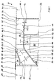
- the tube fan 10 has an outer housing shell 12, which encloses a circular cylindrical, straight cylinder interior. At its left and right end each End wall 14, 16 are outside of the housing shell 12 each one left and right flange 18, 20 firmly attached to the housing shell 12 protrude in the axial direction (axis 22). through these flanges 18, 20 can at both ends of the housing shell 12 and thus at the tube fan 10 each have a tube 24, 26 connected to a pipe not shown become.
- the tube fan 10 can thus between the tubes 24, 26 are installed.
- the outer diameter 28 and 30, respectively the tubes 24 and 26 thus corresponds in present example also the outer diameter 32 of the housing shell 12.
- the tubes 24, 26 could also each one have the outer diameter deviating from the diameter 32 and via a corresponding pipe adapter to the pipe fan be connected.
- the tube fan 10 has a diagonal impeller 40, the input side this fan 10 is present. downstream this Diagonallaufrades 40 is a guide 42 and then the same still a diffuser 44 following the Diagonallaufrad 40 formed within the tubular fan 10.
- the support plate 50 curves end in the axial direction, so that they streamlined the axially aligned intermediate sheath 52nd abuts.
- the flow medium thus flows radially outward on the Carrier disk 50 and past the intermediate casing 52.
- the diagonal impeller 40 has circumferentially distributed blades 54, with its one side on the support plate 50 and with their opposite other side on a cover plate 56th are attached.
- the blades 54 are in the present case Profiled cross-sectionally and also wound. That's theirs upstream inlet edge 55, which is approximately perpendicular to Direction of flow (arrow 58) of the flowing flow medium aligned, provided with a fillet.
- the downstream side Exit edge 60 which is also approximately vertical to the downstream leaving diagonal flow (arrow 62) aligned, has the shape of a tip.
- the cross section the individual blades 54 is in the area between the Carrier plate 50 and the cover plate 56 is not constant, but different sized.
- each blade 54 increases from the region of the cover disk 56 to the region of the support disk 50 from, so that the blade 54 in the region of the support plate 50 on least and in the region of the cover plate 56 most curved is.
- the curvature decrease could, for example, but also be in opposite directions, with the strongest curvature in the area the support disc. This depends on the different flow conditions along the blades 54 between their respective ones Connection area on the cover plate 56 and on the support plate 50 off.
- the leading edge 55 and the trailing edge 60 can be present instead of just arched.
- the curvature of all blades 54 of the diagonal impeller 40 can a so-called forward curvature or reverse curvature exhibit. Which curvature is chosen depends on whether downstream of the impeller the speed energy available there still to be implemented in print or not. With forward curved blades is compared to backward curved blades a stronger deflection of the Flow medium in the area of the blades reached, causing too a larger energy conversion leads to the requirement that the speed energy still downstream, for example is reacted by means of the diffuser 44 in pressure.
- the cover plate 56 runs upstream with a radially aligned End wall 61, which in the present case very narrow. So runs the radially inward bulging initial area 56.1 of the cover plate 56 to the end wall 61 is relatively pointed out.
- the downstream end portion 56.2 of the cover plate 56 has a much stronger downstream tip than the starting area 56.1.
- a angled annular gap 68 present in the present case, the can not be avoided in principle due to the stationary Housing wall 12 and the rotating Diagonallaufrades 40.
- a sealing element 70 which at a distance in an angle in the cover plate 56 molded annular groove 72 engages.
- This angled annular gap 68 represents a flow labyrinth and prevents or complicates that the blades 54 downstream leaving gas flow back through the annular gap 68th again flows into the gap 74, between the cover plate 56 and the housing shell 12 is present. The stronger such a return flow is formed, the lower it becomes the efficiency of the tube fan 10th
- the flow leaving the diagonal impeller 40 then flows through the area of the guide 42.
- this pipe section of the tube fan 10 are between the intermediate jacket 52 and the housing wall vanes 80 are arranged.
- these vanes 80 are in their outer area 80.1, which faces the housing shell 12, more curved than in its inner region 80.2, the intermediate coat 52 faces.
- the helical, Diagonal direction leaving the diagonal impeller 40 Gas flow in an axial flow direction (arrow 84) deflected.
- the vanes 80 are wound three-dimensional and profiled trained.
- the outside of the wall section 52.1 of the intermediate jacket 52nd is formed in the region of the guide vanes 80 planar. It is also possible, the distance between the intermediate sheath 52 and the housing shell 12 in the flow direction itself let enlarge by the intermediate jacket 52 downstream has a decreasing diameter.
- a transverse wall 86 at which the Diagonal impeller 40 driving motor 88 is attached.
- this diffuser 44 is by a downstream increasing flow ring channel between the housing shell 12 and the intermediate jacket 52 constructive realized. So the intermediate jacket 52 is in the area of the diffuser 44 at an angle 90, greater than zero degrees and is less than 30 degrees, inclined to the axial direction 22.1. in the Area of the diffuser 44, this wall section 52.2 is also just like the wall section 52.1 in the area the guide 42 is. However, it is possible the two wall sections 52.1 and 52.2 not with a kink 91, but with a uniform one Curvature to provide cross-sectional jumps in the wall construction the components limiting the flow medium avoid. Also, the wall portion 52.2 in the axial direction be bent, so that the flow ring channel is in the flow direction widened in cross section.
- FIG. 2 tube fan 10.2 different in principle by the tube fan 10 in particular by that its housing jacket 12 of an insulating sleeve 92nd representing insulating material 94 is surrounded.
- This insulation sleeve 92 is each of an end-side Z-shaped pipe frame 96 ring-shaped edged.
- This frame 96 surrounds with a Beading 98 the end edge of the housing shell 12.
- the annular Shape of the housing shell 12 and thus the tube fan 10.2 - makes the attachment of an outer insulation constructive very easy. So are no bulged wall areas of the tube fan present, as is the case in the prior art is that relatively costly dress up with material outside to let.
- the sleeve defined by the intermediate jacket 52 is sound-permeable designed and thus acts sound-absorbing.
- the intermediate sheath is at least in Wall section 52.2 formed as a perforated plate.
Landscapes
- Engineering & Computer Science (AREA)
- Mechanical Engineering (AREA)
- General Engineering & Computer Science (AREA)
- Structures Of Non-Positive Displacement Pumps (AREA)
Abstract
Description
- Fig. 1
- eine halbe Schnittdarstellung eines Rohrventilators nach der Erfindung,
- Fig. 2
- eine Darstellung ähnlich der von Fig. 1 von einem außen gedämmten Rohrventilator nach der Erfindung.
Claims (17)
- Rohrventilator (10, 10.2) für gasförmige Medien,dadurch gekennzeichnet, dassmit einem mehrere Schaufeln (54) aufweisenden Diagonallaufrad (40) undmit einer sich abströmseitig an das Diagonallaufrad (40) anschließenden Leiteinrichtung (42) zur Druckerhöhung des Mediums,die Schaufeln (54) des Diagonallaufrades (40) an einer Tragscheibe (50) und an einer Deckscheibe (56) befestigt sind, undsich die Leiteinrichtung (42) in axialer Richtung (22.1) an das Diagonallaufrad (40) anschließt.
- Rohrventilator nach einem der vorstehenden Ansprüche,
dadurch gekennzeichnet, dasssich der Leiteinrichtung (42) ein abströmseitig allmählich sich vergrößernder Strömungskanal anschließt. - Rohrventilator nach einem der vorstehenden Ansprüche,
dadurch gekennzeichnet, dasssein hohlzylindrisches Gehäuse einen Gehäusemantel (12) besitzt, der längs seiner Zylinderachse (22) konstante Querschnittsmaße aufweist. - Rohrventilator nach einem der vorstehenden Ansprüche,
dadurch gekennzeichnet, dassdie Schaufeln (54) des Laufrades (40) profiliert sind. - Rohrventilator nach einem der vorstehenden Ansprüche,
dadurch gekennzeichnet, dassdie Schaufeln (54) der Leiteinrichtung (42) profiliert sind. - Rohrventilator nach einem der vorstehenden Ansprüche,
dadurch gekennzeichnet, dassdie Schaufeln (54) des Laufrades (40) dreidimensional verwunden sind. - Rohrventilator nach einem der vorstehenden Ansprüche,
dadurch gekennzeichnet, dassdie Schaufeln (54) der Leiteinrichtung (42) dreidimensional verwunden sind. - Rohrventilator nach einem der vorstehenden Ansprüche,
dadurch gekennzeichnet, dasszwischen der Deckscheibe (56) des Laufrades (40) und einem das Laufrad (40) enthaltenden Gehäuse (12) ein Ringspalt (68) vorhanden ist. - Rohrventilator nach Anspruch 8,
dadurch gekennzeichnet, dassder Ringspalt (68) labyrinthartig ausgebildet ist. - Rohrventilator nach einem der vorstehenden Ansprüche,
dadurch gekennzeichnet, dassdas abströmseitige Ende (56.2) der Deckscheibe (56) des Laufrades (40) in etwa in axialer Richtung (22.1) ausgerichtet ist, so dass die Deckscheibe (56) eine allmähliche Krümmung in Richtung Leiteinrichtung (42) aufweist. - Rohrventilator nach einem der vorstehenden Ansprüche,
dadurch gekennzeichnet, dassdie Deckscheibe des Laufrades sich entgegen der Strömungsrichtung düsenartig aufweitet. - Rohrventilator nach einem der vorstehenden Ansprüche,
dadurch gekennzeichnet, dassdas abströmseitige Ende der Tragscheibe (50) des Laufrades (40) in etwa in axialer Richtung (22.1) ausgerichtet ist, so dass die Tragscheibe (50) am Laufradaustritt eine allmähliche Krümmung in Richtung Leiteinrichtung (42) aufweist. - Rohrventilator nach einem der vorstehenden Ansprüche,
dadurch gekennzeichnet, dassder Gehäusemantel (12) von einem schallabsorbierenden Material (94) umgeben ist,der Gehäusemantel (12) schalldurchlässig ist. - Rohrventilator nach Anspruch 13,
dadurch gekennzeichnet, dassdas schallabsorbierende Material (94) von einem weiteren Gehäusemantel (92) umgeben ist. - Rohrventilator nach einem der vorstehenden Ansprüche,
dadurch gekennzeichnet, dassdie Leiteinrichtung (42) aus Kunststoff oder Aluminium besteht. - Rohrventilator nach einem der vorstehenden Ansprüche,
dadurch gekennzeichnet, dassdie Laufradschaufeln (54) aus Kunststoff oder Aluminium bestehen. - Rohrventilator nach einem der vorstehenden Ansprüche,
dadurch gekennzeichnet, dassdie Leiteinrichtung (42) mit dem sich anschließenden, sich vergrößernden Strömungskanal (Diffusor 44) und mit der Aufhängung für den motorischen Antrieb (88) aus einem Teil gefertigt ist.
Applications Claiming Priority (2)
| Application Number | Priority Date | Filing Date | Title |
|---|---|---|---|
| DE20319749U DE20319749U1 (de) | 2003-12-18 | 2003-12-18 | Rohrventilator |
| DE20319749U | 2003-12-18 |
Publications (3)
| Publication Number | Publication Date |
|---|---|
| EP1544472A2 true EP1544472A2 (de) | 2005-06-22 |
| EP1544472A3 EP1544472A3 (de) | 2006-09-13 |
| EP1544472B1 EP1544472B1 (de) | 2014-01-22 |
Family
ID=33441949
Family Applications (1)
| Application Number | Title | Priority Date | Filing Date |
|---|---|---|---|
| EP04029400.1A Expired - Lifetime EP1544472B1 (de) | 2003-12-18 | 2004-12-11 | Rohrventilator |
Country Status (2)
| Country | Link |
|---|---|
| EP (1) | EP1544472B1 (de) |
| DE (1) | DE20319749U1 (de) |
Cited By (4)
| Publication number | Priority date | Publication date | Assignee | Title |
|---|---|---|---|---|
| DE102013107579A1 (de) | 2012-07-17 | 2014-01-23 | Ruck Ventilatoren Gmbh | Ventilator für gasförmige Medien |
| EP2236837A3 (de) * | 2009-03-31 | 2014-10-01 | Behr GmbH & Co. KG | Axiallüfter, insbesondere für ein Kraftfahrzeug |
| CN105402165A (zh) * | 2014-09-09 | 2016-03-16 | 苏州金莱克精密机械有限公司 | 吹风机 |
| US12523239B2 (en) | 2022-11-25 | 2026-01-13 | Ebm-Papst Mulfingen Gmbh & Co. Kg | Fan |
Families Citing this family (8)
| Publication number | Priority date | Publication date | Assignee | Title |
|---|---|---|---|---|
| DE102010032168A1 (de) | 2010-07-23 | 2012-01-26 | Ruck Ventilatoren Gmbh | Diagonal-Ventilator |
| DE102010047489A1 (de) | 2010-10-06 | 2012-04-12 | Ruck Ventilatoren Gmbh | Wandeinbaugebläse |
| DE102012019419A1 (de) | 2012-10-04 | 2014-04-10 | Ruck Ventilatoren Gmbh | Diagonal-Ventilator |
| DE102016215738A1 (de) | 2016-08-23 | 2018-03-01 | Siemens Aktiengesellschaft | Laufrad, Verfahren zur Fertigung |
| GB2573813A (en) | 2018-05-18 | 2019-11-20 | Dyson Technology Ltd | A Compressor |
| DE102018128792A1 (de) * | 2018-11-16 | 2020-05-20 | Ebm-Papst Mulfingen Gmbh & Co. Kg | Kompakter Diagonalventilator mit Nachleiteinrichtung |
| DE102018128791A1 (de) | 2018-11-16 | 2020-05-20 | Ebm-Papst Mulfingen Gmbh & Co. Kg | Diagonalventilator mit Nachleiteinrichtung |
| DE102018128821A1 (de) * | 2018-11-16 | 2020-05-20 | Ebm-Papst Mulfingen Gmbh & Co. Kg | Diagonalventilator mit optimiertem Diagonallaufrad |
Family Cites Families (5)
| Publication number | Priority date | Publication date | Assignee | Title |
|---|---|---|---|---|
| US3059833A (en) * | 1956-10-17 | 1962-10-23 | Remi A Benoit | Fans |
| GB849744A (en) * | 1958-01-30 | 1960-09-28 | Blackman Keith Ltd | Improvements in fans |
| US3191364A (en) * | 1962-05-28 | 1965-06-29 | American Air Filter Co | Centrifugal dust separator |
| DE4020236A1 (de) * | 1990-06-26 | 1992-01-02 | Keller Lufttechnik Gmbh & Co Kg | Innerhalb eines luftansaugkanals angeordnete radialventilatoreinheit |
| MXPA02012408A (es) * | 2000-06-15 | 2004-02-26 | Greenheck Fan Corp | Ventilador centrifugo en linea. |
-
2003
- 2003-12-18 DE DE20319749U patent/DE20319749U1/de not_active Expired - Lifetime
-
2004
- 2004-12-11 EP EP04029400.1A patent/EP1544472B1/de not_active Expired - Lifetime
Cited By (5)
| Publication number | Priority date | Publication date | Assignee | Title |
|---|---|---|---|---|
| EP2236837A3 (de) * | 2009-03-31 | 2014-10-01 | Behr GmbH & Co. KG | Axiallüfter, insbesondere für ein Kraftfahrzeug |
| DE102013107579A1 (de) | 2012-07-17 | 2014-01-23 | Ruck Ventilatoren Gmbh | Ventilator für gasförmige Medien |
| DE102013107579B4 (de) * | 2012-07-17 | 2017-10-26 | Ruck Ventilatoren Gmbh | Ventilator für gasförmige Medien |
| CN105402165A (zh) * | 2014-09-09 | 2016-03-16 | 苏州金莱克精密机械有限公司 | 吹风机 |
| US12523239B2 (en) | 2022-11-25 | 2026-01-13 | Ebm-Papst Mulfingen Gmbh & Co. Kg | Fan |
Also Published As
| Publication number | Publication date |
|---|---|
| EP1544472A3 (de) | 2006-09-13 |
| DE20319749U1 (de) | 2004-11-04 |
| EP1544472B1 (de) | 2014-01-22 |
Similar Documents
| Publication | Publication Date | Title |
|---|---|---|
| EP1608875B1 (de) | Radiallüfterrad, lüftereinheit und radiallüfteranordnung | |
| DE69116091T2 (de) | Kreiselverdichter mit rohrförmigem Diffusor und Kollektor | |
| EP2410183A2 (de) | Diagonal-Ventilator | |
| EP1544472B1 (de) | Rohrventilator | |
| EP2815130A2 (de) | Diffusor, ventilator mit einem solchen diffusor sowie gerät mit solchen ventilatoren | |
| DE1904438A1 (de) | Abstroemgehaeuse einer axialen Turbomaschine | |
| DE1528762B2 (de) | Mehrstufiger Radialverdichter | |
| DE2101628B2 (de) | Überschallkreiselverdichter | |
| EP2140112A1 (de) | Diffusoranordnung | |
| EP2716915A1 (de) | Gehäuse für einen Axialventilator | |
| EP3372838B1 (de) | Raumlufttechnische lüftungsanlage mit einer luftleitanordnung | |
| DE102012106412A1 (de) | Diagonal-Laufrad für einen Diagonal-Ventilator sowie Diagonal-Ventilator | |
| DE3706772C2 (de) | ||
| DE3401210A1 (de) | Schalldaempfer zum anschluss an einen stroemungskanal | |
| EP3009682B1 (de) | Axialventilator mit aussen- und innendiffusor | |
| DE2113514B2 (de) | Überschall-Axialverdichter mit einem zylindrischen oder konischen divergierenden die Einlauföffnung hinten verlängernden Körper | |
| DE2600860C2 (de) | Schalldämpfer auf der Ansaugseite eines Verdichters mit mehreren Dämpfungselementen | |
| CH656434A5 (de) | Zum einbau in kanaelen oder in lueftungs- oder klimageraeten bestimmte ventilatoreinheit. | |
| WO2016110373A1 (de) | Seitenkanalgebläse für eine verbrennungskraftmaschine | |
| DE102012106411A1 (de) | Diagonal-Laufrad für einen Diagonal-Ventilator sowie Diagonal-Ventilator | |
| DE20303443U1 (de) | Radiallüfterrad | |
| DE3515441C2 (de) | ||
| DE3505385C2 (de) | ||
| DE2354126A1 (de) | Radialventilator | |
| DE20319741U1 (de) | Radial- oder Diagonal-Ventilator |
Legal Events
| Date | Code | Title | Description |
|---|---|---|---|
| PUAI | Public reference made under article 153(3) epc to a published international application that has entered the european phase |
Free format text: ORIGINAL CODE: 0009012 |
|
| AK | Designated contracting states |
Kind code of ref document: A2 Designated state(s): AT BE BG CH CY CZ DE DK EE ES FI FR GB GR HU IE IS IT LI LT LU MC NL PL PT RO SE SI SK TR |
|
| AX | Request for extension of the european patent |
Extension state: AL BA HR LV MK YU |
|
| PUAL | Search report despatched |
Free format text: ORIGINAL CODE: 0009013 |
|
| AK | Designated contracting states |
Kind code of ref document: A3 Designated state(s): AT BE BG CH CY CZ DE DK EE ES FI FR GB GR HU IE IS IT LI LT LU MC NL PL PT RO SE SI SK TR |
|
| AX | Request for extension of the european patent |
Extension state: AL BA HR LV MK YU |
|
| 17P | Request for examination filed |
Effective date: 20070127 |
|
| AKX | Designation fees paid |
Designated state(s): AT BE BG CH CY CZ DE DK EE ES FI FR GB GR HU IE IS IT LI LT LU MC NL PL PT RO SE SI SK TR |
|
| 17Q | First examination report despatched |
Effective date: 20071227 |
|
| GRAP | Despatch of communication of intention to grant a patent |
Free format text: ORIGINAL CODE: EPIDOSNIGR1 |
|
| INTG | Intention to grant announced |
Effective date: 20130621 |
|
| GRAS | Grant fee paid |
Free format text: ORIGINAL CODE: EPIDOSNIGR3 |
|
| GRAP | Despatch of communication of intention to grant a patent |
Free format text: ORIGINAL CODE: EPIDOSNIGR1 |
|
| INTG | Intention to grant announced |
Effective date: 20131113 |
|
| RAP1 | Party data changed (applicant data changed or rights of an application transferred) |
Owner name: RUCK VENTILATOREN GMBH |
|
| GRAA | (expected) grant |
Free format text: ORIGINAL CODE: 0009210 |
|
| AK | Designated contracting states |
Kind code of ref document: B1 Designated state(s): AT BE BG CH CY CZ DE DK EE ES FI FR GB GR HU IE IS IT LI LT LU MC NL PL PT RO SE SI SK TR |
|
| REG | Reference to a national code |
Ref country code: GB Ref legal event code: FG4D Free format text: NOT ENGLISH |
|
| REG | Reference to a national code |
Ref country code: CH Ref legal event code: EP |
|
| REG | Reference to a national code |
Ref country code: AT Ref legal event code: REF Ref document number: 650950 Country of ref document: AT Kind code of ref document: T Effective date: 20140215 |
|
| REG | Reference to a national code |
Ref country code: IE Ref legal event code: FG4D Free format text: LANGUAGE OF EP DOCUMENT: GERMAN |
|
| REG | Reference to a national code |
Ref country code: DE Ref legal event code: R096 Ref document number: 502004014508 Country of ref document: DE Effective date: 20140227 |
|
| REG | Reference to a national code |
Ref country code: NL Ref legal event code: VDEP Effective date: 20140122 |
|
| REG | Reference to a national code |
Ref country code: LT Ref legal event code: MG4D |
|
| PG25 | Lapsed in a contracting state [announced via postgrant information from national office to epo] |
Ref country code: IS Free format text: LAPSE BECAUSE OF FAILURE TO SUBMIT A TRANSLATION OF THE DESCRIPTION OR TO PAY THE FEE WITHIN THE PRESCRIBED TIME-LIMIT Effective date: 20140522 Ref country code: LT Free format text: LAPSE BECAUSE OF FAILURE TO SUBMIT A TRANSLATION OF THE DESCRIPTION OR TO PAY THE FEE WITHIN THE PRESCRIBED TIME-LIMIT Effective date: 20140122 |
|
| PG25 | Lapsed in a contracting state [announced via postgrant information from national office to epo] |
Ref country code: CY Free format text: LAPSE BECAUSE OF FAILURE TO SUBMIT A TRANSLATION OF THE DESCRIPTION OR TO PAY THE FEE WITHIN THE PRESCRIBED TIME-LIMIT Effective date: 20140122 Ref country code: SE Free format text: LAPSE BECAUSE OF FAILURE TO SUBMIT A TRANSLATION OF THE DESCRIPTION OR TO PAY THE FEE WITHIN THE PRESCRIBED TIME-LIMIT Effective date: 20140122 Ref country code: ES Free format text: LAPSE BECAUSE OF FAILURE TO SUBMIT A TRANSLATION OF THE DESCRIPTION OR TO PAY THE FEE WITHIN THE PRESCRIBED TIME-LIMIT Effective date: 20140122 Ref country code: PT Free format text: LAPSE BECAUSE OF FAILURE TO SUBMIT A TRANSLATION OF THE DESCRIPTION OR TO PAY THE FEE WITHIN THE PRESCRIBED TIME-LIMIT Effective date: 20140522 Ref country code: FI Free format text: LAPSE BECAUSE OF FAILURE TO SUBMIT A TRANSLATION OF THE DESCRIPTION OR TO PAY THE FEE WITHIN THE PRESCRIBED TIME-LIMIT Effective date: 20140122 Ref country code: NL Free format text: LAPSE BECAUSE OF FAILURE TO SUBMIT A TRANSLATION OF THE DESCRIPTION OR TO PAY THE FEE WITHIN THE PRESCRIBED TIME-LIMIT Effective date: 20140122 |
|
| REG | Reference to a national code |
Ref country code: DE Ref legal event code: R097 Ref document number: 502004014508 Country of ref document: DE |
|
| PG25 | Lapsed in a contracting state [announced via postgrant information from national office to epo] |
Ref country code: CZ Free format text: LAPSE BECAUSE OF FAILURE TO SUBMIT A TRANSLATION OF THE DESCRIPTION OR TO PAY THE FEE WITHIN THE PRESCRIBED TIME-LIMIT Effective date: 20140122 Ref country code: EE Free format text: LAPSE BECAUSE OF FAILURE TO SUBMIT A TRANSLATION OF THE DESCRIPTION OR TO PAY THE FEE WITHIN THE PRESCRIBED TIME-LIMIT Effective date: 20140122 Ref country code: RO Free format text: LAPSE BECAUSE OF FAILURE TO SUBMIT A TRANSLATION OF THE DESCRIPTION OR TO PAY THE FEE WITHIN THE PRESCRIBED TIME-LIMIT Effective date: 20140122 Ref country code: DK Free format text: LAPSE BECAUSE OF FAILURE TO SUBMIT A TRANSLATION OF THE DESCRIPTION OR TO PAY THE FEE WITHIN THE PRESCRIBED TIME-LIMIT Effective date: 20140122 |
|
| PG25 | Lapsed in a contracting state [announced via postgrant information from national office to epo] |
Ref country code: PL Free format text: LAPSE BECAUSE OF FAILURE TO SUBMIT A TRANSLATION OF THE DESCRIPTION OR TO PAY THE FEE WITHIN THE PRESCRIBED TIME-LIMIT Effective date: 20140122 Ref country code: SK Free format text: LAPSE BECAUSE OF FAILURE TO SUBMIT A TRANSLATION OF THE DESCRIPTION OR TO PAY THE FEE WITHIN THE PRESCRIBED TIME-LIMIT Effective date: 20140122 |
|
| PLBE | No opposition filed within time limit |
Free format text: ORIGINAL CODE: 0009261 |
|
| STAA | Information on the status of an ep patent application or granted ep patent |
Free format text: STATUS: NO OPPOSITION FILED WITHIN TIME LIMIT |
|
| 26N | No opposition filed |
Effective date: 20141023 |
|
| REG | Reference to a national code |
Ref country code: DE Ref legal event code: R097 Ref document number: 502004014508 Country of ref document: DE Effective date: 20141023 |
|
| PG25 | Lapsed in a contracting state [announced via postgrant information from national office to epo] |
Ref country code: SI Free format text: LAPSE BECAUSE OF FAILURE TO SUBMIT A TRANSLATION OF THE DESCRIPTION OR TO PAY THE FEE WITHIN THE PRESCRIBED TIME-LIMIT Effective date: 20140122 |
|
| PG25 | Lapsed in a contracting state [announced via postgrant information from national office to epo] |
Ref country code: BE Free format text: LAPSE BECAUSE OF NON-PAYMENT OF DUE FEES Effective date: 20141231 |
|
| PG25 | Lapsed in a contracting state [announced via postgrant information from national office to epo] |
Ref country code: LU Free format text: LAPSE BECAUSE OF FAILURE TO SUBMIT A TRANSLATION OF THE DESCRIPTION OR TO PAY THE FEE WITHIN THE PRESCRIBED TIME-LIMIT Effective date: 20141211 |
|
| REG | Reference to a national code |
Ref country code: CH Ref legal event code: PL |
|
| REG | Reference to a national code |
Ref country code: IE Ref legal event code: MM4A |
|
| REG | Reference to a national code |
Ref country code: FR Ref legal event code: ST Effective date: 20150831 |
|
| PG25 | Lapsed in a contracting state [announced via postgrant information from national office to epo] |
Ref country code: IE Free format text: LAPSE BECAUSE OF NON-PAYMENT OF DUE FEES Effective date: 20141211 Ref country code: LI Free format text: LAPSE BECAUSE OF NON-PAYMENT OF DUE FEES Effective date: 20141231 Ref country code: CH Free format text: LAPSE BECAUSE OF NON-PAYMENT OF DUE FEES Effective date: 20141231 |
|
| PG25 | Lapsed in a contracting state [announced via postgrant information from national office to epo] |
Ref country code: FR Free format text: LAPSE BECAUSE OF NON-PAYMENT OF DUE FEES Effective date: 20141231 |
|
| REG | Reference to a national code |
Ref country code: AT Ref legal event code: MM01 Ref document number: 650950 Country of ref document: AT Kind code of ref document: T Effective date: 20141211 |
|
| PG25 | Lapsed in a contracting state [announced via postgrant information from national office to epo] |
Ref country code: BG Free format text: LAPSE BECAUSE OF FAILURE TO SUBMIT A TRANSLATION OF THE DESCRIPTION OR TO PAY THE FEE WITHIN THE PRESCRIBED TIME-LIMIT Effective date: 20140122 Ref country code: AT Free format text: LAPSE BECAUSE OF NON-PAYMENT OF DUE FEES Effective date: 20141211 Ref country code: MC Free format text: LAPSE BECAUSE OF FAILURE TO SUBMIT A TRANSLATION OF THE DESCRIPTION OR TO PAY THE FEE WITHIN THE PRESCRIBED TIME-LIMIT Effective date: 20140122 |
|
| PG25 | Lapsed in a contracting state [announced via postgrant information from national office to epo] |
Ref country code: IT Free format text: LAPSE BECAUSE OF FAILURE TO SUBMIT A TRANSLATION OF THE DESCRIPTION OR TO PAY THE FEE WITHIN THE PRESCRIBED TIME-LIMIT Effective date: 20140122 Ref country code: GR Free format text: LAPSE BECAUSE OF FAILURE TO SUBMIT A TRANSLATION OF THE DESCRIPTION OR TO PAY THE FEE WITHIN THE PRESCRIBED TIME-LIMIT Effective date: 20140423 |
|
| PG25 | Lapsed in a contracting state [announced via postgrant information from national office to epo] |
Ref country code: TR Free format text: LAPSE BECAUSE OF FAILURE TO SUBMIT A TRANSLATION OF THE DESCRIPTION OR TO PAY THE FEE WITHIN THE PRESCRIBED TIME-LIMIT Effective date: 20140122 Ref country code: HU Free format text: LAPSE BECAUSE OF FAILURE TO SUBMIT A TRANSLATION OF THE DESCRIPTION OR TO PAY THE FEE WITHIN THE PRESCRIBED TIME-LIMIT; INVALID AB INITIO Effective date: 20041211 |
|
| PGFP | Annual fee paid to national office [announced via postgrant information from national office to epo] |
Ref country code: GB Payment date: 20211222 Year of fee payment: 18 |
|
| GBPC | Gb: european patent ceased through non-payment of renewal fee |
Effective date: 20221211 |
|
| PG25 | Lapsed in a contracting state [announced via postgrant information from national office to epo] |
Ref country code: GB Free format text: LAPSE BECAUSE OF NON-PAYMENT OF DUE FEES Effective date: 20221211 |
|
| REG | Reference to a national code |
Ref country code: DE Ref legal event code: R082 Ref document number: 502004014508 Country of ref document: DE Representative=s name: GLEIM PETRI PATENT- UND RECHTSANWALTSPARTNERSC, DE |
|
| PGFP | Annual fee paid to national office [announced via postgrant information from national office to epo] |
Ref country code: DE Payment date: 20231211 Year of fee payment: 20 |
|
| REG | Reference to a national code |
Ref country code: DE Ref legal event code: R071 Ref document number: 502004014508 Country of ref document: DE |