EP1544129B1 - Récipient thermoformé en matière plastique et méthodes pour sa fabrication - Google Patents
Récipient thermoformé en matière plastique et méthodes pour sa fabrication Download PDFInfo
- Publication number
- EP1544129B1 EP1544129B1 EP20040022757 EP04022757A EP1544129B1 EP 1544129 B1 EP1544129 B1 EP 1544129B1 EP 20040022757 EP20040022757 EP 20040022757 EP 04022757 A EP04022757 A EP 04022757A EP 1544129 B1 EP1544129 B1 EP 1544129B1
- Authority
- EP
- European Patent Office
- Prior art keywords
- container
- base portion
- raised features
- base
- hollow raised
- Prior art date
- Legal status (The legal status is an assumption and is not a legal conclusion. Google has not performed a legal analysis and makes no representation as to the accuracy of the status listed.)
- Not-in-force
Links
Images

Classifications
-
- B—PERFORMING OPERATIONS; TRANSPORTING
- B65—CONVEYING; PACKING; STORING; HANDLING THIN OR FILAMENTARY MATERIAL
- B65D—CONTAINERS FOR STORAGE OR TRANSPORT OF ARTICLES OR MATERIALS, e.g. BAGS, BARRELS, BOTTLES, BOXES, CANS, CARTONS, CRATES, DRUMS, JARS, TANKS, HOPPERS, FORWARDING CONTAINERS; ACCESSORIES, CLOSURES, OR FITTINGS THEREFOR; PACKAGING ELEMENTS; PACKAGES
- B65D81/00—Containers, packaging elements, or packages, for contents presenting particular transport or storage problems, or adapted to be used for non-packaging purposes after removal of contents
- B65D81/02—Containers, packaging elements, or packages, for contents presenting particular transport or storage problems, or adapted to be used for non-packaging purposes after removal of contents specially adapted to protect contents from mechanical damage
-
- B—PERFORMING OPERATIONS; TRANSPORTING
- B29—WORKING OF PLASTICS; WORKING OF SUBSTANCES IN A PLASTIC STATE IN GENERAL
- B29C—SHAPING OR JOINING OF PLASTICS; SHAPING OF MATERIAL IN A PLASTIC STATE, NOT OTHERWISE PROVIDED FOR; AFTER-TREATMENT OF THE SHAPED PRODUCTS, e.g. REPAIRING
- B29C51/00—Shaping by thermoforming, i.e. shaping sheets or sheet like preforms after heating, e.g. shaping sheets in matched moulds or by deep-drawing; Apparatus therefor
- B29C51/04—Combined thermoforming and prestretching, e.g. biaxial stretching
- B29C51/06—Combined thermoforming and prestretching, e.g. biaxial stretching using pressure difference for prestretching
-
- B—PERFORMING OPERATIONS; TRANSPORTING
- B29—WORKING OF PLASTICS; WORKING OF SUBSTANCES IN A PLASTIC STATE IN GENERAL
- B29C—SHAPING OR JOINING OF PLASTICS; SHAPING OF MATERIAL IN A PLASTIC STATE, NOT OTHERWISE PROVIDED FOR; AFTER-TREATMENT OF THE SHAPED PRODUCTS, e.g. REPAIRING
- B29C51/00—Shaping by thermoforming, i.e. shaping sheets or sheet like preforms after heating, e.g. shaping sheets in matched moulds or by deep-drawing; Apparatus therefor
- B29C51/26—Component parts, details or accessories; Auxiliary operations
- B29C51/30—Moulds
- B29C51/34—Moulds for undercut articles
- B29C51/343—Moulds for undercut articles having recessed undersurfaces
-
- B—PERFORMING OPERATIONS; TRANSPORTING
- B29—WORKING OF PLASTICS; WORKING OF SUBSTANCES IN A PLASTIC STATE IN GENERAL
- B29C—SHAPING OR JOINING OF PLASTICS; SHAPING OF MATERIAL IN A PLASTIC STATE, NOT OTHERWISE PROVIDED FOR; AFTER-TREATMENT OF THE SHAPED PRODUCTS, e.g. REPAIRING
- B29C2791/00—Shaping characteristics in general
- B29C2791/001—Shaping in several steps
-
- B—PERFORMING OPERATIONS; TRANSPORTING
- B29—WORKING OF PLASTICS; WORKING OF SUBSTANCES IN A PLASTIC STATE IN GENERAL
- B29C—SHAPING OR JOINING OF PLASTICS; SHAPING OF MATERIAL IN A PLASTIC STATE, NOT OTHERWISE PROVIDED FOR; AFTER-TREATMENT OF THE SHAPED PRODUCTS, e.g. REPAIRING
- B29C2791/00—Shaping characteristics in general
- B29C2791/004—Shaping under special conditions
- B29C2791/006—Using vacuum
-
- B—PERFORMING OPERATIONS; TRANSPORTING
- B29—WORKING OF PLASTICS; WORKING OF SUBSTANCES IN A PLASTIC STATE IN GENERAL
- B29C—SHAPING OR JOINING OF PLASTICS; SHAPING OF MATERIAL IN A PLASTIC STATE, NOT OTHERWISE PROVIDED FOR; AFTER-TREATMENT OF THE SHAPED PRODUCTS, e.g. REPAIRING
- B29C2791/00—Shaping characteristics in general
- B29C2791/004—Shaping under special conditions
- B29C2791/007—Using fluid under pressure
-
- B—PERFORMING OPERATIONS; TRANSPORTING
- B29—WORKING OF PLASTICS; WORKING OF SUBSTANCES IN A PLASTIC STATE IN GENERAL
- B29C—SHAPING OR JOINING OF PLASTICS; SHAPING OF MATERIAL IN A PLASTIC STATE, NOT OTHERWISE PROVIDED FOR; AFTER-TREATMENT OF THE SHAPED PRODUCTS, e.g. REPAIRING
- B29C51/00—Shaping by thermoforming, i.e. shaping sheets or sheet like preforms after heating, e.g. shaping sheets in matched moulds or by deep-drawing; Apparatus therefor
- B29C51/04—Combined thermoforming and prestretching, e.g. biaxial stretching
-
- B—PERFORMING OPERATIONS; TRANSPORTING
- B29—WORKING OF PLASTICS; WORKING OF SUBSTANCES IN A PLASTIC STATE IN GENERAL
- B29C—SHAPING OR JOINING OF PLASTICS; SHAPING OF MATERIAL IN A PLASTIC STATE, NOT OTHERWISE PROVIDED FOR; AFTER-TREATMENT OF THE SHAPED PRODUCTS, e.g. REPAIRING
- B29C51/00—Shaping by thermoforming, i.e. shaping sheets or sheet like preforms after heating, e.g. shaping sheets in matched moulds or by deep-drawing; Apparatus therefor
- B29C51/08—Deep drawing or matched-mould forming, i.e. using mechanical means only
-
- B—PERFORMING OPERATIONS; TRANSPORTING
- B29—WORKING OF PLASTICS; WORKING OF SUBSTANCES IN A PLASTIC STATE IN GENERAL
- B29C—SHAPING OR JOINING OF PLASTICS; SHAPING OF MATERIAL IN A PLASTIC STATE, NOT OTHERWISE PROVIDED FOR; AFTER-TREATMENT OF THE SHAPED PRODUCTS, e.g. REPAIRING
- B29C51/00—Shaping by thermoforming, i.e. shaping sheets or sheet like preforms after heating, e.g. shaping sheets in matched moulds or by deep-drawing; Apparatus therefor
- B29C51/10—Forming by pressure difference, e.g. vacuum
-
- B—PERFORMING OPERATIONS; TRANSPORTING
- B29—WORKING OF PLASTICS; WORKING OF SUBSTANCES IN A PLASTIC STATE IN GENERAL
- B29L—INDEXING SCHEME ASSOCIATED WITH SUBCLASS B29C, RELATING TO PARTICULAR ARTICLES
- B29L2031/00—Other particular articles
- B29L2031/712—Containers; Packaging elements or accessories, Packages
- B29L2031/7132—Bowls, Cups, Glasses
-
- B—PERFORMING OPERATIONS; TRANSPORTING
- B65—CONVEYING; PACKING; STORING; HANDLING THIN OR FILAMENTARY MATERIAL
- B65D—CONTAINERS FOR STORAGE OR TRANSPORT OF ARTICLES OR MATERIALS, e.g. BAGS, BARRELS, BOTTLES, BOXES, CANS, CARTONS, CRATES, DRUMS, JARS, TANKS, HOPPERS, FORWARDING CONTAINERS; ACCESSORIES, CLOSURES, OR FITTINGS THEREFOR; PACKAGING ELEMENTS; PACKAGES
- B65D85/00—Containers, packaging elements or packages, specially adapted for particular articles or materials
- B65D85/30—Containers, packaging elements or packages, specially adapted for particular articles or materials for articles particularly sensitive to damage by shock or pressure
- B65D85/34—Containers, packaging elements or packages, specially adapted for particular articles or materials for articles particularly sensitive to damage by shock or pressure for fruit, e.g. apples, oranges or tomatoes
Definitions
- the present invention relates to a thermoformed plastic container, useful for the packaging of soft products that might be easily bruised, and to the process for the manufacture thereof.
- thermoformed plastic container for soft food and non food products, which container comprises a base portion and sidewalls extending upwardly from the periphery of the base portion, and is characterised in that said base portion is thermoformed in such a way that an array of hollow raised features with a flexible upper portion (also called here “soft caps”), project upwardly therefrom.
- the container of the present invention will thus be characterised by a base or a part of it that is softened by the presence of these soft caps projecting towards the inner cavity of the container, and will therefore be particularly useful for the packaging of easily bruised products.
- a protective pad of e.g. non woven material or air cushioning material such as Sealed Air's Bubble-Wrap®, glued to the base portion which is used to prevent the damage to the products by the rigid base of the container.
- a separate protective pad presents however several drawbacks. It is in fact necessary to provide for an additional, separate and dedicated step, in the product packaging process or in the process for the manufacture of the container, to position the separate pad into the container.
- a first object of the present invention is therefore a one-piece thermoformed plastic container with a base portion and sidewalls extending upwardly from the periphery of said base portion said container being characterised in that the base comprises an array of hollow raised features having an upper flexible portion projected upwardly from said base.
- a second object of the present invention is a thermoforming process designed for the manufacture of the one-piece plastic container of the first object.
- a third object of the present invention is a package of a soft product wherein the soft product is loaded into a container according to the first object of the present invention and the package is closed by lidding or wrapping the filled container.
- the base (10) of the container (1) of the present invention comprises an array of hollow raised features (11) that are obtained by a thermoforming step.
- each hollow raised feature is characterised by a flexible upper portion which is obtained by the thinning of the plastic web, with respect to the plastic web of the base portion, due to the thermoforming stretching.
- thermoforming process in fact those parts that have been stretched the least are the thickest while those that have been stretched the most are the thinnest.
- the upper portion of the raised features will have to be less than 100 ⁇ m, preferably less than 80 ⁇ m and more preferably less than 60 ⁇ m thick, such as 10, 15, 20, 25, 30, 35, 40, 45, 50, or 55 ⁇ m thick.
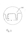
- the width of the raised features expressed as the diameter of the hemisphere or cylinder to which each of the hollow raised feature (11) can be approximated, and indicated in Figure 2 as "a" would be typically less than 20 mm, preferably less than 18 mm and more preferably less than 15 mm.
- soft caps larger than 20 mm might compromise the stability of the container, depending on the composition of the web and mainly on the number and distribution of the soft caps on the base portion.
- a suitable width for the hollow raised features (11) would therefore be about 5, 6, 7, 8, 9, 10, 11, 12, 13, 14, or 15 mm, with the central range, i.e. 7, 8, 9, 10, 11, 12, being preferred.
- the height of the hollow raised features (the distance of the top of the hollow raised feature from the plane of the base, indicated in Figure 2 as "b") would typically be from one fifth of their width to a value about equal to their width. Preferably their height would be at least one fourth of their width and even more preferably at least one third up to a value that is slightly less than their width. Thus, for soft caps with e.g. a width of about 10 mm, a preferred height would be from about 3 to about 9 mm.
- the raised hollow features (11) are preferably in evenly spaced relation.
- the distance between two adjacent features would be large enough to maintain the desired rigidity to the base and the container but not too large to disrupt the softening effect.
- the distance between two adjacent raised features (indicated in Figure 2 as "c") would be from at least about 1 mm to about 10 mm, preferably from about 1 mm to about 8 mm, more preferably from about 2 mm to about 6 mm.
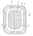
- the hollow raised features (11) will be distributed in parallel rows, as illustrated in Figure 3 , or in offset rows (not shown) or in concentric rings (also not shown) or in spiral form (also not shown) or in any other substantially regular pattern. Not necessarily however they need to cover the whole surface of the base portion.
- the array of hollow raised features (11) will be positioned in the central portion of the base as illustrated for instance in Figure 3 and will cover at least 50 %, preferably at least 60 %, more preferably at least 70 %, and even more preferably at least 80 % of the surface of the base portion.
- the hollow raised features (11) are represented as cylinders or hemispheres ("bubbles"). However they may also have a different shape. For instance they may be V-shaped or rod-shaped caps arranged alternatively in several rows such that caps in adjacent rows oppose each other.
- the above description concerning size and distribution of soft caps having a cylinder or hemisphere shape can be applied analogously also to soft caps of a different shape.
- hollow raised features (11) of essentially the same size are preferred, particularly because this will simplify the manufacturing process, this however is not a strict requirement to get the desired softening effect as for instance alternating smaller and larger soft caps, or alternating soft caps of different shape, may further improve the protecting effect.
- flanges (12) will project upwardly from the periphery of the base ending up into a top flange (13) that is the upper periphery of the container and extends around its open top in a continuous unbroken manner.
- Said flange is typically planar and parallel to the plane of the base. Its width is not critical. If the container has to be closed by heat-sealing a lidding film or sheet onto the flange, then the flange should be at least 3-4 mm wide. Otherwise, if the container has to be closed by wrapping up, or by snapping on a mating rigid lid or cover as known in the art, the flange may be smaller than that or even a mere bead. As illustrated in Figure 1 , the flange may have a skirt (14).
- the sidewalls (12) are substantially upright as in Figure 1 , to give the container the shape of a punnet, but alternatively they may also project outwardly to give the container the shape of a conventional tray.
- a plurality of ribs (15) is generally present in the sidewalls (12) to provide for the desired vertical stiffness.
- Corrugations lines that may be parallel flutes, furrows, ridges, crests or grooves (16) may be formed also in the base portion, in the part thereof that does not comprise the raised features (11).
- the container is also provided with a downwardly projecting element (17), that may be in the form of a continuous annular element extending over the whole perimetric portion of the base (10), at a slightly retracted position relative to the edge where the base (10) connects with the sidewalls (12), or it may be in the form of discrete projecting elements typically at the corners of the base (10), with a flat bottom external surface to serve as support for the container.
- a downwardly projecting element (17) may be in the form of a continuous annular element extending over the whole perimetric portion of the base (10), at a slightly retracted position relative to the edge where the base (10) connects with the sidewalls (12), or it may be in the form of discrete projecting elements typically at the corners of the base (10), with a flat bottom external surface to serve as support for the container.
- a rigid covering lid may be included and unitarily formed with the container.
- the lid and the container are a single continuous piece of material formed simultaneously with a hinge, formed integrally therewith, which on deformation allows the covering lid to swing backwards and forwards on opening and closing the receptacle.
- the polymeric materials that can be used in the manufacture of the container of the present invention can include any polymers that fulfill the purposes of the invention or which, with the addition of additives can be modified to fulfill the purposes of the invention.
- Polymers suitable include polyolefins, such as polypropylenes and polyethylenes, polyvinyl chloride, polyesters, co-polyesters, polyamides, co-polyamides, polystyrene, polystyrene copolymers, and the like polymers. It is also possible to use blends of suitable polymers, particularly when one of the components of the blend is used in a minor amount as an impact modifier to increase flexural modulus and crack resistance.
- the container is typically highly permeable and often it is also perforated to allow the exchange of gases with the environment.
- the presence of discrete projecting elements (17) will be particularly preferred because by suitably selecting a gas permeable material for the container and/or suitably creating small perforations therein, the exchange of gases with the environment will be possible also for the items packaged in contact with the bottom of the container.
- gas-barrier properties may be required e.g. to maintain a suitably modified or controlled atmosphere within the package that would prolong the shelf life of the packaged food product.
- the material used for the container will comprise a gas-barrier layer, typically comprising ethylenevinyl alcohol copolymers, nylons, or blends thereof, set in order to provide the materials with an Oxygen Transmission Rate (OTR) (evaluated by following the method described in ASTM D-3985 and using an OX-TRAN instrument by Mocon) lower than 250, preferably lower than 125 cm 3 /m 2 .d.atm, when measured at 23 °C and 0 % of relative humidity.
- OTR Oxygen Transmission Rate
- the multi-layer structure will also comprise a heat-sealable resin such as a polyethylene resin, as the innermost layer (i.e. the skin or external layer of the container which is closer to the food product), to improve the sealability properties of the container, and a bulk layer of a polymer or polymer blend such as those indicated above.
- a heat-sealable resin such as a polyethylene resin
- the innermost layer i.e. the skin or external layer of the container which is closer to the food product
- a bulk layer of a polymer or polymer blend such as those indicated above.
- thermoplastic material used for the container of the present invention may be transparent, either clear or colored, translucent, either clear or colored, or opaque.
- the sheet used for the manufacture of the container of the invention may be obtained by extrusion, and in case of a multilayer sheet by co-extrusion, or by conventional lamination techniques and is then converted into container (1) by a two-step thermoforming process.
- a container with a substantially flat base portion is formed and in the second the array of hollow raised features is created in said substantially flat base portion.
- thermoforming steps can be carried out, one immediately after the other, in the same, suitably designed, thermoforming machine or they can be carried out separately using a conventional thermoforming machine for the first step and a suitably designed forming device for the second one.
- the conversion of the sheet into a container according to the present invention is carried out by a first step of negative thermoforming using a concave, female mould having an essentially flat base, where the heat-softened plastic is drawn down over the mould by drawing a vacuum through the mould, optionally with the assistance of a suitable plug, followed by a second step of inverted negative thermoforming, where the array of hollow raised features with a flexible upper portion is created into the base of the container by blowing air from the base of the concave mould against a suitably shaped positive plug mould that compresses the formed sheet against the base of the concave mould and/or by suitably applying a negative pressure through said shaped positive plug mould.
- the sidewalls, the base corner and top flange areas of the female mould are cooled during the entire process by chilled water circulating within the metal body of the mould.
- the central base area of the mould however is never cooled during the entire thermoforming process.
- This central portion of the female mould base may on the other hand also be heated, e.g. by electrical element heaters or circulating hot fluids (water, oil, etc.).
- the central shaped portion of the plug assist is held inside the main body of the plug until the second, re-forming, step takes place.
- Said central shaped portion is lowered towards the female mould in said second step of inverted negative thermoforming to allow the subsequent re-forming of the base area of the mould-shaped plastic to create the desired array of raised features therein.
- Said separate shaped portion of the plug assist is cooled by circulating chilled water and once this second thermoforming step is completed, and the soft caps are blown and/or sucked against the surface of the shaped central portion of the plug assist, this allows a rapid temperature drop. With the reduced temperature the shaped plastic container becomes stable and can suitably be removed from the mould without being distorted.
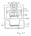
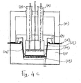
- (21) represents the heated and softened thermoformable sheet which is fed between the two halves of the tool, the upper one, pressure box (22), and the lower one, mould (23).
- the two halves are separated.
- the tool closes sealing sheet (21) against the top of the lower mould (23) and the open end of the pressure box (22).
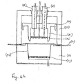
- Plug (25) then moves towards the cavity (24) of the mould (23) until it has completed its travel and is stopped by the plug stopping plate (29) and at the same time a positive pressure is applied to pressure box (22) through the plug pillars (28) and the plug "soft caps” mould plate (26) while a negative pressure (vacuum) is applied to cavity (24) via the cavity vented plate (27), pushing sheet (21) against said plate (27) ( Figure 4c ).
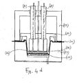
- the plug "soft caps” mould plate (26) has moved further down to face the formed sheet (21) in contact with the cavity vented plate (27).
- the positive pressure that was applied through the plug "soft caps” mould (26) is switched to a negative pressure and the negative pressure applied through the cavity vented plate (27) is switched to a positive air pressure to create the array of hollow raised features (11) mating the shape of the plug "soft caps” mould plate (26).
- the sidewalls, base corner and top flange areas of the mould (23), but not the central base portion are cooled by chilled circulating water. Also cooled by circulating cold water is the plug "soft caps" mould plate (26).
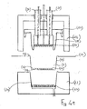
- a container with a substantially flat base portion is manufactured by a conventional thermoforming process and then submitted to a secondary forming step using a suitably designed forming device to create the array of hollow raised features (11).
- a heated plate (30) with raised pins (31) is mechanically driven into the flat base portion (10') of the preformed container (32).
- a counter impression recessed cooled plate (33) acts on the opposite side of the base portion of the container.
- the introduction of the heated pins (31) softens the areas of the container base portion in contact therewith.
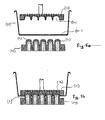
- positive air pressure is supplied through the pins (31) forcing the softened material into the counter impression plate (33).
- the recesses (34) in this plate can be vented to atmosphere or have a vacuum applied to remove the air blown through the pins (31).
- the heated pins (31) are smaller in size (diameter) than the recesses (34).
- the heated pins (31) should soften the base portion sufficiently to enable air to blow the plastic material off the pins (31) and into the recesses (34).
- the shape of the recesses (34) and their size is what defines the final shape of the raised hollow features (11), while the heated pins (31) only pre-stretch the material into the approximate shape.
- thermoforming process of the present invention typically at least the first forming step is carried out on a webstock of material, even if in line of principle separated cut sheets could also be employed.
- suitably designed cutting means separate the containers, one from the other, if prepared from a webstock, and trim out the excess plastic material.
- the thickness of sheet (21), used as starting material in the above described thermoforming process would be generally within the range of from about 150 ⁇ m to about 1,000 ⁇ m, preferably from about 160 ⁇ m to about 900 ⁇ m, even more preferably from about 170 ⁇ m to about 800 ⁇ m, most preferably from about 180 ⁇ m to about 700 ⁇ m, mainly depending on the height desired for the tray and therefore on the depth of the first thermoforming step.
- Thermoplastic materials suitable for the manufacture of the wrapping or lidding sheet or film include mono- and multi-layer films, oriented or non oriented, and, if oriented, heat-shrinkable or heat-set.
- Monolayer structures will typically comprise polyolefins (such as propylene-based polymers or, preferably cross-linked, polyethylene-based polymers) or polyesters.
- Multi-layer structures will comprise at least an outer sealing layer, generally an outer heat-sealing layer, and an outer abuse layer. These multi-layer structure may include additional inner layers, such as gas-barrier layers, if a gas-barrier package is desired, bulk layers, and tie layers, as known in the art.
- Suitable rigid lids will generally be made by thermoforming, using the same plastic material of the container.
- cardboard may also be employed.
Claims (11)
- Contenant plastique thermoformé en une pièce, à dessus ouvert (1), avec une portion de base (10) et des parois latérales (12) s'étendant vers le haut depuis la périphérie de ladite portion de base, ledit contenant étant caractérisé en ce que la base comprend une rangée de caractéristiques creuses relevées (11) ayant une portion flexible supérieure faisant saillie vers le haut depuis ladite base.
- Contenant selon la revendication 1, dans lequel la portion supérieure flexible des caractéristiques relevées creuses (11), obtenue par l'amincissement de la bande plastique, par rapport à la portion de base, dû à l'étirage sous thermoformage, possède une épaisseur inférieure à 100µm, de préférence inférieure à 80µm et selon la plus grande préférence une épaisseur inférieure à 60µm, comme une épaisseur de 10, 15, 20, 25, 30, 35, 40, 45, 50 ou 55µm.
- Contenant selon la revendication 1, dans lequel les caractéristiques relevées creuses (11) sont réalisées comme de petits cylindres ou hémisphères ("bulles").
- Contenant selon la revendication 3, dans lequel la largeur des caractéristiques relevées creuses (11), exprimée comme diamètre de l'hémisphère ou du cylindre, est d'environ 5, 6, 7, 8, 9, 10, 11, 12, 13, 14 ou 15 mm, et leur hauteur, la distance du dessus de la caractéristique relevée depuis le plan de la base, représente un cinquième de leur largeur à une valeur environ égale à leur largeur.
- Contenant selon la revendication 1, dans lequel les caractéristiques relevées creuses (11) se trouvent dans une relation uniformément espacée avec une distance entre deux caractéristiques relevées adjacentes d'au moins environ 1 mm à environ 10 mm, de préférence d'au moins environ 1 mm à environ 8 mm, selon une plus grande préférence d'environ 2 mm à environ 6 mm.
- Contenant selon l'une quelconque des revendications précédentes, dans lequel la rangée de caractéristiques relevées creuses (11) est positionnée dans la portion centrale de la base (10) et couvre au moins 50%, de préférence au moins 60%, selon une plus grande préférence au moins 70% et selon une préférence encore plus grande au moins 80% de la surface de la portion de base.
- Contenant selon l'une quelconque des revendications précédentes, qui est réalisé en un polymère sélectionné parmi des polypropylènes, polyéthylènes, polyvinylchlorure, polyesters, copolyesters, polyamides, copolyamides, polystyrène et copolymères de polystyrène.
- Contenant selon l'une quelconque des revendications précédentes, qui est perforé pour permettre l'échange de gaz entre le contenant et l'environnement.
- Procédé de fabrication d'un contenant selon la revendication 1, par un processus de thermoformage en deux étapes, comprenant une première étape consistant à former un contenant avec une portion de base sensiblement plate et une deuxième étape consistant à former une rangée de caractéristiques relevées creuses dans celle-ci.
- Procédé selon la revendication 9, dans lequel ladite deuxième étape consistant à former une rangée de caractéristiques relevées creuses dans la portion de base sensiblement plate du contenant est accomplie soit en soufflant de l'air depuis en dessous de la portion de base ramollie sensiblement plate contre un moule bouchon positif configuré d'une manière appropriée et/ou en appliquant une pression négative à travers ledit moule positif configuré, ou en entraînant une plaque d'axes chauffés dans la portion de base sensiblement plate et en forçant le matériau ainsi ramolli de ladite portion de base dans un moule positif configuré d'une manière appropriée en soufflant l'air à travers lesdits axes.
- Emballage d'un produit mou, où le produit mou est chargé dans un contenant selon l'une quelconque des revendications 1 à 8, et l'emballage est fermé en appliquant un couvercle ou en enveloppant le contenant rempli.
Priority Applications (1)
| Application Number | Priority Date | Filing Date | Title |
|---|---|---|---|
| EP20040022757 EP1544129B1 (fr) | 2003-10-15 | 2004-09-24 | Récipient thermoformé en matière plastique et méthodes pour sa fabrication |
Applications Claiming Priority (3)
| Application Number | Priority Date | Filing Date | Title |
|---|---|---|---|
| EP03023337A EP1524202A1 (fr) | 2003-10-15 | 2003-10-15 | Récipient thermoformé en matière plastique et méthodes pour sa fabrication |
| EP03023337 | 2003-10-15 | ||
| EP20040022757 EP1544129B1 (fr) | 2003-10-15 | 2004-09-24 | Récipient thermoformé en matière plastique et méthodes pour sa fabrication |
Publications (2)
| Publication Number | Publication Date |
|---|---|
| EP1544129A1 EP1544129A1 (fr) | 2005-06-22 |
| EP1544129B1 true EP1544129B1 (fr) | 2010-05-05 |
Family
ID=34524703
Family Applications (1)
| Application Number | Title | Priority Date | Filing Date |
|---|---|---|---|
| EP20040022757 Not-in-force EP1544129B1 (fr) | 2003-10-15 | 2004-09-24 | Récipient thermoformé en matière plastique et méthodes pour sa fabrication |
Country Status (1)
| Country | Link |
|---|---|
| EP (1) | EP1544129B1 (fr) |
Families Citing this family (7)
| Publication number | Priority date | Publication date | Assignee | Title |
|---|---|---|---|---|
| FR2918350B1 (fr) * | 2007-07-03 | 2012-01-13 | Cgl Pack Service | Barquette pour contenir des aliments |
| ES2637189T3 (es) * | 2008-06-17 | 2017-10-11 | Cryovac, Inc. | Bandeja termoplástica |
| CA2804720C (fr) | 2010-07-16 | 2018-05-01 | Cascades Canada Ulc | Recipient en matiere plastique |
| NL1040614C2 (nl) | 2014-01-21 | 2015-07-22 | Multitray B V | Doosvormige houder uit kunststof voor fruit. |
| GB2580685B (en) * | 2019-01-24 | 2021-04-28 | Softform Ltd | A method and tool for manufacturing a container from a thermoplastic material |
| GB2599178B (en) * | 2019-01-24 | 2023-11-22 | Softform Ltd | A container formed from a thermoplastic material |
| GB2590476B (en) | 2019-12-19 | 2023-02-01 | Softform Ltd | A method and tool for manufacturing a container from a thermoplastic material |
Family Cites Families (4)
| Publication number | Priority date | Publication date | Assignee | Title |
|---|---|---|---|---|
| FR2715373B1 (fr) * | 1994-01-24 | 1996-04-05 | Robert Bourjala | Cagette en matière plastique. |
| US5954203A (en) * | 1997-12-24 | 1999-09-21 | Allegiance Corporation | Packaging container |
| US6443309B1 (en) * | 2000-05-15 | 2002-09-03 | Victory Packaging, Inc. | Apparatus for packaging goods |
| FR2816923B3 (fr) * | 2000-11-17 | 2003-01-03 | Quatre C Sarl | Emballage unitaire d'objet fragile ou non de differentes formes et dimensions entrant dans un cabarit admissible |
-
2004
- 2004-09-24 EP EP20040022757 patent/EP1544129B1/fr not_active Not-in-force
Also Published As
| Publication number | Publication date |
|---|---|
| EP1544129A1 (fr) | 2005-06-22 |
Similar Documents
| Publication | Publication Date | Title |
|---|---|---|
| CA1298772C (fr) | Procede de fabrication d'un emballage sous vide, avec pellicule; et produits ainsi obtenus | |
| CN1520375A (zh) | 扁瓶形状香烟容器和包装香烟的方法 | |
| JP4157130B2 (ja) | 射出成形材料により封入されるかまたは射出成形材料から成形されるリムまたは他の特徴部を有する容器 | |
| US6286705B1 (en) | Container having tapered sidewall made from sheet material and lid to seal same | |
| EP2310278B1 (fr) | Plateau thermoplastique | |
| US5253801A (en) | Multi sided food tray | |
| US20020092852A1 (en) | Reclosable container | |
| EP1675776B1 (fr) | Ensemble d'emballage rigide et refermable | |
| EP3184453B1 (fr) | Conteneur scellable, conteneur scellé et leur procédé de fabrication | |
| US20210245914A1 (en) | Laminate Container | |
| EP2279135A1 (fr) | Contenant moulé à soupape de dégazage | |
| EP2998239B1 (fr) | Barquette, récipient hermétiquement fermé et leur procédé de production | |
| JPH0761436A (ja) | 包装容器及びその成形方法 | |
| NO872187L (no) | Emballasje egnet som retorte. | |
| ES2899155T3 (es) | Recipiente para envasado alimenticio, método para producción y método para producir un envase que comprende tal recipiente | |
| EP1544129B1 (fr) | Récipient thermoformé en matière plastique et méthodes pour sa fabrication | |
| KR102462013B1 (ko) | 재활용 가능한 빙과류 포장지 | |
| EP1524202A1 (fr) | Récipient thermoformé en matière plastique et méthodes pour sa fabrication | |
| EP3826846B1 (fr) | Récipient en carton stratifié avec un film thermoplastique rigide | |
| JPH05213358A (ja) | 包装容器 | |
| NL2028740B1 (en) | Method of manufacturing packaging components with pre-applied seal | |
| JP2021049995A (ja) | 蓋体および蓋体付きカップ状容器 | |
| JP3064034B2 (ja) | 鏡餅容器の製造方法 | |
| JPH0245352A (ja) | 金属蓋付容器とその製造方法 | |
| JPH04201846A (ja) | 金属蓋付容器 |
Legal Events
| Date | Code | Title | Description |
|---|---|---|---|
| PUAI | Public reference made under article 153(3) epc to a published international application that has entered the european phase |
Free format text: ORIGINAL CODE: 0009012 |
|
| AK | Designated contracting states |
Kind code of ref document: A1 Designated state(s): AT BE BG CH CY CZ DE DK EE ES FI FR GB GR HU IE IT LI LU MC NL PL PT RO SE SI SK TR |
|
| AX | Request for extension of the european patent |
Extension state: AL HR LT LV MK |
|
| 17P | Request for examination filed |
Effective date: 20051222 |
|
| AKX | Designation fees paid |
Designated state(s): AT BE BG CH CY CZ DE DK EE ES FI FR GB GR HU IE IT LI LU MC NL PL PT RO SE SI SK TR |
|
| GRAP | Despatch of communication of intention to grant a patent |
Free format text: ORIGINAL CODE: EPIDOSNIGR1 |
|
| GRAS | Grant fee paid |
Free format text: ORIGINAL CODE: EPIDOSNIGR3 |
|
| GRAA | (expected) grant |
Free format text: ORIGINAL CODE: 0009210 |
|
| AK | Designated contracting states |
Kind code of ref document: B1 Designated state(s): AT BE BG CH CY CZ DE DK EE ES FI FR GB GR HU IE IT LI LU MC NL PL PT RO SE SI SK TR |
|
| REG | Reference to a national code |
Ref country code: GB Ref legal event code: FG4D |
|
| REG | Reference to a national code |
Ref country code: CH Ref legal event code: EP |
|
| REG | Reference to a national code |
Ref country code: IE Ref legal event code: FG4D |
|
| REF | Corresponds to: |
Ref document number: 602004026987 Country of ref document: DE Date of ref document: 20100617 Kind code of ref document: P |
|
| REG | Reference to a national code |
Ref country code: ES Ref legal event code: FG2A Ref document number: 2342598 Country of ref document: ES Kind code of ref document: T3 |
|
| REG | Reference to a national code |
Ref country code: NL Ref legal event code: VDEP Effective date: 20100505 |
|
| PG25 | Lapsed in a contracting state [announced via postgrant information from national office to epo] |
Ref country code: SE Free format text: LAPSE BECAUSE OF FAILURE TO SUBMIT A TRANSLATION OF THE DESCRIPTION OR TO PAY THE FEE WITHIN THE PRESCRIBED TIME-LIMIT Effective date: 20100505 Ref country code: NL Free format text: LAPSE BECAUSE OF FAILURE TO SUBMIT A TRANSLATION OF THE DESCRIPTION OR TO PAY THE FEE WITHIN THE PRESCRIBED TIME-LIMIT Effective date: 20100505 |
|
| PG25 | Lapsed in a contracting state [announced via postgrant information from national office to epo] |
Ref country code: AT Free format text: LAPSE BECAUSE OF FAILURE TO SUBMIT A TRANSLATION OF THE DESCRIPTION OR TO PAY THE FEE WITHIN THE PRESCRIBED TIME-LIMIT Effective date: 20100505 Ref country code: SI Free format text: LAPSE BECAUSE OF FAILURE TO SUBMIT A TRANSLATION OF THE DESCRIPTION OR TO PAY THE FEE WITHIN THE PRESCRIBED TIME-LIMIT Effective date: 20100505 Ref country code: FI Free format text: LAPSE BECAUSE OF FAILURE TO SUBMIT A TRANSLATION OF THE DESCRIPTION OR TO PAY THE FEE WITHIN THE PRESCRIBED TIME-LIMIT Effective date: 20100505 |
|
| PG25 | Lapsed in a contracting state [announced via postgrant information from national office to epo] |
Ref country code: GR Free format text: LAPSE BECAUSE OF FAILURE TO SUBMIT A TRANSLATION OF THE DESCRIPTION OR TO PAY THE FEE WITHIN THE PRESCRIBED TIME-LIMIT Effective date: 20100806 Ref country code: CY Free format text: LAPSE BECAUSE OF FAILURE TO SUBMIT A TRANSLATION OF THE DESCRIPTION OR TO PAY THE FEE WITHIN THE PRESCRIBED TIME-LIMIT Effective date: 20100505 Ref country code: PL Free format text: LAPSE BECAUSE OF FAILURE TO SUBMIT A TRANSLATION OF THE DESCRIPTION OR TO PAY THE FEE WITHIN THE PRESCRIBED TIME-LIMIT Effective date: 20100505 |
|
| PG25 | Lapsed in a contracting state [announced via postgrant information from national office to epo] |
Ref country code: DK Free format text: LAPSE BECAUSE OF FAILURE TO SUBMIT A TRANSLATION OF THE DESCRIPTION OR TO PAY THE FEE WITHIN THE PRESCRIBED TIME-LIMIT Effective date: 20100505 Ref country code: PT Free format text: LAPSE BECAUSE OF FAILURE TO SUBMIT A TRANSLATION OF THE DESCRIPTION OR TO PAY THE FEE WITHIN THE PRESCRIBED TIME-LIMIT Effective date: 20100906 Ref country code: EE Free format text: LAPSE BECAUSE OF FAILURE TO SUBMIT A TRANSLATION OF THE DESCRIPTION OR TO PAY THE FEE WITHIN THE PRESCRIBED TIME-LIMIT Effective date: 20100505 |
|
| PGFP | Annual fee paid to national office [announced via postgrant information from national office to epo] |
Ref country code: NL Payment date: 20100924 Year of fee payment: 7 |
|
| PG25 | Lapsed in a contracting state [announced via postgrant information from national office to epo] |
Ref country code: SK Free format text: LAPSE BECAUSE OF FAILURE TO SUBMIT A TRANSLATION OF THE DESCRIPTION OR TO PAY THE FEE WITHIN THE PRESCRIBED TIME-LIMIT Effective date: 20100505 Ref country code: RO Free format text: LAPSE BECAUSE OF FAILURE TO SUBMIT A TRANSLATION OF THE DESCRIPTION OR TO PAY THE FEE WITHIN THE PRESCRIBED TIME-LIMIT Effective date: 20100505 Ref country code: CZ Free format text: LAPSE BECAUSE OF FAILURE TO SUBMIT A TRANSLATION OF THE DESCRIPTION OR TO PAY THE FEE WITHIN THE PRESCRIBED TIME-LIMIT Effective date: 20100505 Ref country code: BE Free format text: LAPSE BECAUSE OF FAILURE TO SUBMIT A TRANSLATION OF THE DESCRIPTION OR TO PAY THE FEE WITHIN THE PRESCRIBED TIME-LIMIT Effective date: 20100505 |
|
| PLBE | No opposition filed within time limit |
Free format text: ORIGINAL CODE: 0009261 |
|
| STAA | Information on the status of an ep patent application or granted ep patent |
Free format text: STATUS: NO OPPOSITION FILED WITHIN TIME LIMIT |
|
| 26N | No opposition filed |
Effective date: 20110208 |
|
| PG25 | Lapsed in a contracting state [announced via postgrant information from national office to epo] |
Ref country code: MC Free format text: LAPSE BECAUSE OF NON-PAYMENT OF DUE FEES Effective date: 20100930 |
|
| REG | Reference to a national code |
Ref country code: CH Ref legal event code: PL |
|
| REG | Reference to a national code |
Ref country code: DE Ref legal event code: R097 Ref document number: 602004026987 Country of ref document: DE Effective date: 20110207 |
|
| PG25 | Lapsed in a contracting state [announced via postgrant information from national office to epo] |
Ref country code: LI Free format text: LAPSE BECAUSE OF NON-PAYMENT OF DUE FEES Effective date: 20100930 Ref country code: CH Free format text: LAPSE BECAUSE OF NON-PAYMENT OF DUE FEES Effective date: 20100930 Ref country code: IE Free format text: LAPSE BECAUSE OF NON-PAYMENT OF DUE FEES Effective date: 20100924 |
|
| PG25 | Lapsed in a contracting state [announced via postgrant information from national office to epo] |
Ref country code: LU Free format text: LAPSE BECAUSE OF NON-PAYMENT OF DUE FEES Effective date: 20100924 Ref country code: BG Free format text: LAPSE BECAUSE OF FAILURE TO SUBMIT A TRANSLATION OF THE DESCRIPTION OR TO PAY THE FEE WITHIN THE PRESCRIBED TIME-LIMIT Effective date: 20100505 Ref country code: HU Free format text: LAPSE BECAUSE OF FAILURE TO SUBMIT A TRANSLATION OF THE DESCRIPTION OR TO PAY THE FEE WITHIN THE PRESCRIBED TIME-LIMIT Effective date: 20101106 |
|
| PG25 | Lapsed in a contracting state [announced via postgrant information from national office to epo] |
Ref country code: TR Free format text: LAPSE BECAUSE OF FAILURE TO SUBMIT A TRANSLATION OF THE DESCRIPTION OR TO PAY THE FEE WITHIN THE PRESCRIBED TIME-LIMIT Effective date: 20100505 |
|
| PG25 | Lapsed in a contracting state [announced via postgrant information from national office to epo] |
Ref country code: BG Free format text: LAPSE BECAUSE OF FAILURE TO SUBMIT A TRANSLATION OF THE DESCRIPTION OR TO PAY THE FEE WITHIN THE PRESCRIBED TIME-LIMIT Effective date: 20100805 |
|
| REG | Reference to a national code |
Ref country code: FR Ref legal event code: PLFP Year of fee payment: 12 |
|
| PGFP | Annual fee paid to national office [announced via postgrant information from national office to epo] |
Ref country code: ES Payment date: 20150928 Year of fee payment: 12 Ref country code: GB Payment date: 20150928 Year of fee payment: 12 |
|
| PGFP | Annual fee paid to national office [announced via postgrant information from national office to epo] |
Ref country code: FR Payment date: 20150917 Year of fee payment: 12 |
|
| PGFP | Annual fee paid to national office [announced via postgrant information from national office to epo] |
Ref country code: IT Payment date: 20150923 Year of fee payment: 12 |
|
| PGFP | Annual fee paid to national office [announced via postgrant information from national office to epo] |
Ref country code: DE Payment date: 20150929 Year of fee payment: 12 |
|
| REG | Reference to a national code |
Ref country code: DE Ref legal event code: R081 Ref document number: 602004026987 Country of ref document: DE Owner name: FAERCH PLAST POOLE LTD, GB Free format text: FORMER OWNER: CRYOVAC, INC., DUNCAN, S.C., US |
|
| REG | Reference to a national code |
Ref country code: ES Ref legal event code: PC2A Owner name: FAERCH PLAST POOLE LTD Effective date: 20160415 |
|
| REG | Reference to a national code |
Ref country code: FR Ref legal event code: TP Owner name: FAERCH PLAST POOLE LTD, GB Effective date: 20160323 |
|
| REG | Reference to a national code |
Ref country code: GB Ref legal event code: 732E Free format text: REGISTERED BETWEEN 20160407 AND 20160413 |
|
| REG | Reference to a national code |
Ref country code: DE Ref legal event code: R119 Ref document number: 602004026987 Country of ref document: DE |
|
| GBPC | Gb: european patent ceased through non-payment of renewal fee |
Effective date: 20160924 |
|
| REG | Reference to a national code |
Ref country code: FR Ref legal event code: ST Effective date: 20170531 |
|
| PG25 | Lapsed in a contracting state [announced via postgrant information from national office to epo] |
Ref country code: FR Free format text: LAPSE BECAUSE OF NON-PAYMENT OF DUE FEES Effective date: 20160930 Ref country code: GB Free format text: LAPSE BECAUSE OF NON-PAYMENT OF DUE FEES Effective date: 20160924 Ref country code: DE Free format text: LAPSE BECAUSE OF NON-PAYMENT OF DUE FEES Effective date: 20170401 |
|
| PG25 | Lapsed in a contracting state [announced via postgrant information from national office to epo] |
Ref country code: IT Free format text: LAPSE BECAUSE OF NON-PAYMENT OF DUE FEES Effective date: 20160924 |
|
| PG25 | Lapsed in a contracting state [announced via postgrant information from national office to epo] |
Ref country code: ES Free format text: LAPSE BECAUSE OF NON-PAYMENT OF DUE FEES Effective date: 20160925 |
|
| REG | Reference to a national code |
Ref country code: ES Ref legal event code: FD2A Effective date: 20181126 |