EP1544081A1 - Elément déformable pour un véhicule - Google Patents
Elément déformable pour un véhicule Download PDFInfo
- Publication number
- EP1544081A1 EP1544081A1 EP04025707A EP04025707A EP1544081A1 EP 1544081 A1 EP1544081 A1 EP 1544081A1 EP 04025707 A EP04025707 A EP 04025707A EP 04025707 A EP04025707 A EP 04025707A EP 1544081 A1 EP1544081 A1 EP 1544081A1
- Authority
- EP
- European Patent Office
- Prior art keywords
- profile
- deformation element
- vehicle
- carrier
- support
- Prior art date
- Legal status (The legal status is an assumption and is not a legal conclusion. Google has not performed a legal analysis and makes no representation as to the accuracy of the status listed.)
- Granted
Links
Images


Classifications
-
- B—PERFORMING OPERATIONS; TRANSPORTING
- B62—LAND VEHICLES FOR TRAVELLING OTHERWISE THAN ON RAILS
- B62D—MOTOR VEHICLES; TRAILERS
- B62D21/00—Understructures, i.e. chassis frame on which a vehicle body may be mounted
- B62D21/15—Understructures, i.e. chassis frame on which a vehicle body may be mounted having impact absorbing means, e.g. a frame designed to permanently or temporarily change shape or dimension upon impact with another body
- B62D21/152—Front or rear frames
-
- H—ELECTRICITY
- H01—ELECTRIC ELEMENTS
- H01L—SEMICONDUCTOR DEVICES NOT COVERED BY CLASS H10
- H01L2224/00—Indexing scheme for arrangements for connecting or disconnecting semiconductor or solid-state bodies and methods related thereto as covered by H01L24/00
- H01L2224/01—Means for bonding being attached to, or being formed on, the surface to be connected, e.g. chip-to-package, die-attach, "first-level" interconnects; Manufacturing methods related thereto
- H01L2224/42—Wire connectors; Manufacturing methods related thereto
- H01L2224/47—Structure, shape, material or disposition of the wire connectors after the connecting process
- H01L2224/48—Structure, shape, material or disposition of the wire connectors after the connecting process of an individual wire connector
- H01L2224/4805—Shape
- H01L2224/4809—Loop shape
- H01L2224/48091—Arched
Definitions
- the invention relates to a deformation element for a motor vehicle after Preamble of claim 1.
- a deformation element for a motor vehicle which comprises a pipe section with a round cross-section, in the reinforcing struts and webs are provided in the longitudinal and transverse directions.
- a cross member for a vehicle known in transverse and Has longitudinally extending hollow chambers, which are divided by webs.
- the object of the invention is a deformation element in the front or To create rear of a motor vehicle, which absorbs energy in a crash acts.
- the advantages achieved by the invention are that by a so-called Insert made of profile beams in the trunk of a vehicle in a crash Energy is absorbed by the profile beam can deform.
- the deformation element of a contiguous triangular-shaped component with one transverse to the vehicle aligned - viewed in the direction of travel of the vehicle F - front profile carrier exists at which - in relation to the direction of travel of the vehicle to the rear connect running further profile carrier, the free rear ends of a transverse support plate are connected to each other, based on the vehicle body supported.
- the connection of the profile carrier with each other is such that at the ends of the front profile carrier in each case an obliquely backward running profile carrier is attached, wherein an inner wall surface of the profile carrier at the front end of the front profile carrier is present and the front ends of the other Profile beams are exposed.
- the front profile carrier has at least two in Profile carrier longitudinal direction extending and divided over an inner web wall Hollow chambers, which are square in cross-section.
- the oblique Rear running profile carrier each have at least three on two inner Web walls separated in profile carrier longitudinal direction extending hollow chambers, the are executed in quadrangular cross-section.
- the crash on the one hand in the middle of the Vehicle received by the transversely arranged in the vehicle profile carrier and from the side or from the outsides is the crash of the profile beams in each case from the front, that is, received approximately from the front side.
- the arranged profiled supports extend from the front transverse profile carrier behind - seen in the direction of travel of the vehicle - together and form between them and the front profile support a triangular space. This will be a Jacking the profile beam in a crash not hindered.
- the final support plate has a protruding from the plane of the plate Support profile, which in an indentation of a transverse wall or a transverse Built-up profile of the vehicle body structure is embedded supporting.
- the support profile of Support plate is in a transverse wall or a profile of the vehicle body so embedded that behind the wall or the profile is still a free space, so that at a crash the deformation is not hindered by the profile.
- the lower surface the profile carrier of the bearing surface of the boot cavity in the vehicle body structure in is approximately adapted, such that a front lower portion of the profile support a beveled and then rounded bearing surface, which in a Front edge of a flat surface of the profile carrier expires.
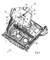
- a deformation element 3 is arranged, which consists of at least three composite profile beams 4, 5 and 6, which form a structural unit. This is connected to the bottom 8 of the trunk cavity 1 via screw 10.
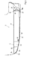
- the Deformationselment 3 consists of a transverse to the vehicle - in Direction of travel F of the vehicle seen - front profile carrier 4, where two connect further profile carrier 5 and 6, which extend in the vehicle longitudinal direction. These profile beams 5 and 6 may be oriented obliquely or otherwise.
- the obliquely oriented profile carrier 5 and 6 close the transversely aligned Profile carrier 4 at the front between them such that the inner side surfaces 11, 12 of the profile carrier 5, 6 with the end edges E3, E4 of the profile carrier 4 by Welds 14, 14a are interconnected.
- the free the profile carrier. 4 opposite ends E1, E2 of the other profile beams 5, 6 are via a support plate 15th firmly connected to each other, located on a transverse profile 16 or a Wall of the vehicle body supported, which is shown in more detail in Fig. 4.
- the profile beams 4, 5 and 6 are made of extruded aluminum sections and have Hollow chambers, which are separated by web walls.
- the transversely in the Vehicle-oriented profile carrier 4 in profile carrier longitudinal direction A-A extending Hollow chambers 4a and 4b, which are separated by an inner web wall 20.
- the further arranged obliquely, that is at an angle ⁇ to the profile carrier. 4 employed further profile carrier 5 and 6 have in profile carrier longitudinal direction B-B extending hollow chambers 5a, 5b and 5c and 6a, 6b and 6c, on the inner Web walls S1, S2 are separated from each other.
- the profile beams 4, 5 and 6 are connected together in such a way to form a structural unit, that results in a total of a lower surface 21 of all profile beams 4, 5 and 6, the Support surface 22 of the boot cavity 8 is approximately adapted.
- the cross arranged profiled support 4 a slightly rounded lower surface 23, which in a front end edge 24 of the hollow chamber 4a ends.
- the obliquely arranged profile carrier 5 and 6 extend from the transverse in the vehicle aligned front section beam 4 to the rear - with respect to the direction of travel of the Seen vehicle - together and form between itself with the profile carrier 4 a triangular space L.
- a support of the assembly consisting of the three profile beams 4, 5 and 6 takes place on the vehicle body on the transverse profile 16 or on a mounting wall. These are the free ones Ends E1 and E2 of the profile beams 5 and 6 fixedly connected to the support plate 15, which is over the entire width b of the profile carrier 5 and 6 extends.
- a connection of Support plate 15 with the profile beams 5, 6 via welds, the free Ends E1 and E2 of the profile carrier 5, 6 of legs 26, 27 of the support plate 15th are overlapped, which is shown in more detail in Fig. 4.
- the support plate 15 For support on the transverse profile 16, the support plate 15 has a positioning so-called projecting support profile 15a, which in a recessed receptacle 25th of the transverse profile 16 or a structural wall is arranged embedded. Behind the Recording 25 is a free space provided.
Landscapes
- Engineering & Computer Science (AREA)
- Chemical & Material Sciences (AREA)
- Combustion & Propulsion (AREA)
- Transportation (AREA)
- Mechanical Engineering (AREA)
- Body Structure For Vehicles (AREA)
- Vibration Dampers (AREA)
Applications Claiming Priority (2)
| Application Number | Priority Date | Filing Date | Title |
|---|---|---|---|
| DE10360170 | 2003-12-20 | ||
| DE10360170A DE10360170B3 (de) | 2003-12-20 | 2003-12-20 | Deformationselement für ein Kraftfahrzeug |
Publications (2)
| Publication Number | Publication Date |
|---|---|
| EP1544081A1 true EP1544081A1 (fr) | 2005-06-22 |
| EP1544081B1 EP1544081B1 (fr) | 2008-12-24 |
Family
ID=34306446
Family Applications (1)
| Application Number | Title | Priority Date | Filing Date |
|---|---|---|---|
| EP04025707A Expired - Fee Related EP1544081B1 (fr) | 2003-12-20 | 2004-10-29 | Elément déformable pour un véhicule |
Country Status (4)
| Country | Link |
|---|---|
| US (1) | US7201433B2 (fr) |
| EP (1) | EP1544081B1 (fr) |
| JP (1) | JP4012538B2 (fr) |
| DE (2) | DE10360170B3 (fr) |
Families Citing this family (10)
| Publication number | Priority date | Publication date | Assignee | Title |
|---|---|---|---|---|
| DE102005004780B3 (de) * | 2005-02-01 | 2006-09-07 | Dr.Ing.H.C. F. Porsche Ag | Deformationselement für ein Kraftfahrzeug |
| DE102007023391B4 (de) * | 2007-05-18 | 2019-05-02 | Dr. Ing. H.C. F. Porsche Aktiengesellschaft | Schutzgehäuse für eine Fahrzeugbatterie und Kraftfahrzeug mit einem derartigen Schutzgehäuse |
| DE102007023392A1 (de) * | 2007-05-18 | 2008-11-20 | Dr. Ing. H.C. F. Porsche Aktiengesellschaft | Schutzgehäuse für eine Fahrzeugbatterie |
| DE102007026680A1 (de) | 2007-06-08 | 2008-12-11 | Dr. Ing. H.C. F. Porsche Aktiengesellschaft | Deformationselement |
| DE102008052970B4 (de) | 2008-10-23 | 2020-06-18 | Dr. Ing. H.C. F. Porsche Aktiengesellschaft | Versteifungsboden für ein Kraftfahrzeug |
| DE102008060581A1 (de) | 2008-12-04 | 2010-06-10 | Dr.Ing.H.C.F.Porsche Aktiengesellschaft | Fahrzeug |
| US8820823B1 (en) | 2013-03-12 | 2014-09-02 | Honda Motor Co., Ltd. | Vehicle frame structure |
| ES2504891B2 (es) * | 2013-04-04 | 2015-02-27 | Filiberto ANTOLÍN MONDORUZA | Sistema antiempotramiento de vehículos en choque frontal |
| US10005349B2 (en) * | 2015-12-29 | 2018-06-26 | Ford Global Technologies, Llc | Structural underbody support in a vehicle |
| US10946898B2 (en) * | 2019-07-17 | 2021-03-16 | GM Global Technology Operations LLC | Close coupled four rail front structure system transferring compressive loads into a single center torsion/compression member |
Citations (3)
| Publication number | Priority date | Publication date | Assignee | Title |
|---|---|---|---|---|
| DE2357419A1 (de) * | 1973-11-14 | 1975-05-15 | Guenter Teetz | Anpralldaempfer fuer kraftfahrzeuge |
| DE20313810U1 (de) * | 2003-09-04 | 2003-11-13 | Mundhenke Erich | Fahrzeug - Passive Sicherheit |
| EP1454815A2 (fr) * | 2003-03-04 | 2004-09-08 | Audi Ag | Structure de chassis |
Family Cites Families (8)
| Publication number | Priority date | Publication date | Assignee | Title |
|---|---|---|---|---|
| US5071188A (en) * | 1989-10-04 | 1991-12-10 | Volkswagen Ag | Frame structure for an end region of a motor vehicle |
| ZA973413B (en) * | 1996-04-30 | 1998-10-21 | Autokinetics Inc | Modular vehicle frame |
| DE19726720C1 (de) * | 1997-06-24 | 1998-10-08 | Daimler Benz Ag | Strukturbauteil |
| DE19733191A1 (de) * | 1997-07-31 | 1999-02-18 | Porsche Ag | Querträger für Fahrzeuge |
| EP1125798B1 (fr) * | 2000-02-17 | 2006-05-03 | Kabushiki Kaisha Kobe Seiko Sho | Assemblage de renforcement pour pare-chocs et support de pare-chocs |
| DE10062689B4 (de) * | 2000-12-15 | 2005-09-01 | Audi Ag | Deformationselement für ein Kraftfahrzeug |
| JP2004188998A (ja) * | 2002-12-06 | 2004-07-08 | Honda Motor Co Ltd | 車体フレーム |
| JP4486337B2 (ja) * | 2003-10-14 | 2010-06-23 | 富士重工業株式会社 | 車両のフレーム構造 |
-
2003
- 2003-12-20 DE DE10360170A patent/DE10360170B3/de not_active Expired - Fee Related
-
2004
- 2004-10-29 EP EP04025707A patent/EP1544081B1/fr not_active Expired - Fee Related
- 2004-10-29 DE DE502004008730T patent/DE502004008730D1/de active Active
- 2004-12-03 US US11/002,115 patent/US7201433B2/en not_active Expired - Fee Related
- 2004-12-15 JP JP2004363610A patent/JP4012538B2/ja not_active Expired - Fee Related
Patent Citations (3)
| Publication number | Priority date | Publication date | Assignee | Title |
|---|---|---|---|---|
| DE2357419A1 (de) * | 1973-11-14 | 1975-05-15 | Guenter Teetz | Anpralldaempfer fuer kraftfahrzeuge |
| EP1454815A2 (fr) * | 2003-03-04 | 2004-09-08 | Audi Ag | Structure de chassis |
| DE20313810U1 (de) * | 2003-09-04 | 2003-11-13 | Mundhenke Erich | Fahrzeug - Passive Sicherheit |
Also Published As
| Publication number | Publication date |
|---|---|
| DE502004008730D1 (de) | 2009-02-05 |
| EP1544081B1 (fr) | 2008-12-24 |
| DE10360170B3 (de) | 2005-04-14 |
| US7201433B2 (en) | 2007-04-10 |
| JP4012538B2 (ja) | 2007-11-21 |
| JP2005178758A (ja) | 2005-07-07 |
| US20050134088A1 (en) | 2005-06-23 |
Similar Documents
| Publication | Publication Date | Title |
|---|---|---|
| DE4013784C2 (de) | Wagenkasten, insbesondere für Personenkraftwagen | |
| DE4018593C2 (de) | Aufrechte Säule für eine Fahrzeug-Aufbaustruktur | |
| DE10023193B4 (de) | Fahrzeugaufbau für einen Vorderwagen eines Kraftfahrzeugs | |
| EP0547346B1 (fr) | Superstructure pour véhicule automobile, spécialement pour véhicule de tourisme | |
| DE102005004780B3 (de) | Deformationselement für ein Kraftfahrzeug | |
| EP1152910B1 (fr) | Composant de vehicule automobile | |
| DE102008036335A1 (de) | Versteifungsvorrichtung | |
| DE4204826A1 (de) | Wagenkasten fuer kraftfahrzeuge, insbesondere personenkraftwagen | |
| DE2936866A1 (de) | Karosserie fuer ein fahrzeug und mit dieser karosserie ausgestattetes fahrzeug | |
| DE102010045586A1 (de) | Rahmenstruktur für den Karosserieboden eines Kraftfahrzeuges, Bodeneinheit, Unterbau und Fahrzeugkarosserie | |
| WO2005019015A1 (fr) | Structure de noeud pour relier deux profiles dans un cadre porteur de vehicule | |
| DE10203055A1 (de) | Fußstütze für ein Fahrzeug | |
| DE19958996A1 (de) | Querträgermodul für einen front- oder heckseitigen Stirnbereich eines Kraftfahrzeugs | |
| EP1995156A1 (fr) | Structure portante d'un véhicule automobile | |
| DE102008036870A1 (de) | Fahrzeugaufbau | |
| DE10360170B3 (de) | Deformationselement für ein Kraftfahrzeug | |
| DE19802806C2 (de) | Integralträger zur Aufnahme von Funktionsaggregaten eines Kraftfahrzeugs | |
| DE102007041382B4 (de) | Reserveradmulde für ein Kraftfahrzeug | |
| EP1262395B1 (fr) | Structure de chassis pour véhicule automobile avec poutres composées | |
| DE10218701C1 (de) | Überrollbügelanordnung für ein Kraftfahrzeug | |
| EP1216891A2 (fr) | Elément de déformation absorbeur d'énergie | |
| WO2004024538A1 (fr) | Carrosserie de voiture avec montant | |
| DE102005006200B4 (de) | Dachrahmen für ein Kraftfahrzeug | |
| DE19752073A1 (de) | Kraftfahrzeugkarosserie mit einem Strukturquerträger | |
| DE10032663B4 (de) | Kraftwagen mit einer selbsttragenden Karosserie |
Legal Events
| Date | Code | Title | Description |
|---|---|---|---|
| PUAI | Public reference made under article 153(3) epc to a published international application that has entered the european phase |
Free format text: ORIGINAL CODE: 0009012 |
|
| AK | Designated contracting states |
Kind code of ref document: A1 Designated state(s): AT BE BG CH CY CZ DE DK EE ES FI FR GB GR HU IE IT LI LU MC NL PL PT RO SE SI SK TR |
|
| AX | Request for extension of the european patent |
Extension state: AL HR LT LV MK |
|
| 17P | Request for examination filed |
Effective date: 20051222 |
|
| AKX | Designation fees paid |
Designated state(s): DE ES FR GB IT |
|
| RAP1 | Party data changed (applicant data changed or rights of an application transferred) |
Owner name: DR. ING. H.C. F. PORSCHE AKTIENGESELLSCHAFT |
|
| RAP1 | Party data changed (applicant data changed or rights of an application transferred) |
Owner name: DR. ING. H.C. F. PORSCHE AKTIENGESELLSCHAFT |
|
| GRAP | Despatch of communication of intention to grant a patent |
Free format text: ORIGINAL CODE: EPIDOSNIGR1 |
|
| GRAS | Grant fee paid |
Free format text: ORIGINAL CODE: EPIDOSNIGR3 |
|
| GRAA | (expected) grant |
Free format text: ORIGINAL CODE: 0009210 |
|
| AK | Designated contracting states |
Kind code of ref document: B1 Designated state(s): DE ES FR GB IT |
|
| REG | Reference to a national code |
Ref country code: GB Ref legal event code: FG4D Free format text: NOT ENGLISH |
|
| REF | Corresponds to: |
Ref document number: 502004008730 Country of ref document: DE Date of ref document: 20090205 Kind code of ref document: P |
|
| PG25 | Lapsed in a contracting state [announced via postgrant information from national office to epo] |
Ref country code: ES Free format text: LAPSE BECAUSE OF FAILURE TO SUBMIT A TRANSLATION OF THE DESCRIPTION OR TO PAY THE FEE WITHIN THE PRESCRIBED TIME-LIMIT Effective date: 20090404 |
|
| PLBE | No opposition filed within time limit |
Free format text: ORIGINAL CODE: 0009261 |
|
| STAA | Information on the status of an ep patent application or granted ep patent |
Free format text: STATUS: NO OPPOSITION FILED WITHIN TIME LIMIT |
|
| 26N | No opposition filed |
Effective date: 20090925 |
|
| PGFP | Annual fee paid to national office [announced via postgrant information from national office to epo] |
Ref country code: FR Payment date: 20101104 Year of fee payment: 7 |
|
| REG | Reference to a national code |
Ref country code: FR Ref legal event code: TP |
|
| PGFP | Annual fee paid to national office [announced via postgrant information from national office to epo] |
Ref country code: GB Payment date: 20101021 Year of fee payment: 7 Ref country code: IT Payment date: 20101022 Year of fee payment: 7 |
|
| REG | Reference to a national code |
Ref country code: GB Ref legal event code: 732E Free format text: REGISTERED BETWEEN 20110310 AND 20110316 |
|
| REG | Reference to a national code |
Ref country code: GB Ref legal event code: 732E Free format text: REGISTERED BETWEEN 20110331 AND 20110406 |
|
| GBPC | Gb: european patent ceased through non-payment of renewal fee |
Effective date: 20111029 |
|
| REG | Reference to a national code |
Ref country code: FR Ref legal event code: ST Effective date: 20120629 |
|
| PG25 | Lapsed in a contracting state [announced via postgrant information from national office to epo] |
Ref country code: GB Free format text: LAPSE BECAUSE OF NON-PAYMENT OF DUE FEES Effective date: 20111029 Ref country code: IT Free format text: LAPSE BECAUSE OF NON-PAYMENT OF DUE FEES Effective date: 20111029 Ref country code: FR Free format text: LAPSE BECAUSE OF NON-PAYMENT OF DUE FEES Effective date: 20111102 |
|
| PGFP | Annual fee paid to national office [announced via postgrant information from national office to epo] |
Ref country code: DE Payment date: 20151015 Year of fee payment: 12 |
|
| REG | Reference to a national code |
Ref country code: DE Ref legal event code: R119 Ref document number: 502004008730 Country of ref document: DE |
|
| PG25 | Lapsed in a contracting state [announced via postgrant information from national office to epo] |
Ref country code: DE Free format text: LAPSE BECAUSE OF NON-PAYMENT OF DUE FEES Effective date: 20170503 |