EP1544003A1 - Dispositif d'attelage pour véhicules automobiles - Google Patents
Dispositif d'attelage pour véhicules automobiles Download PDFInfo
- Publication number
- EP1544003A1 EP1544003A1 EP04030203A EP04030203A EP1544003A1 EP 1544003 A1 EP1544003 A1 EP 1544003A1 EP 04030203 A EP04030203 A EP 04030203A EP 04030203 A EP04030203 A EP 04030203A EP 1544003 A1 EP1544003 A1 EP 1544003A1
- Authority
- EP
- European Patent Office
- Prior art keywords
- housing
- fixed
- worm
- worm wheel
- vehicle
- Prior art date
- Legal status (The legal status is an assumption and is not a legal conclusion. Google has not performed a legal analysis and makes no representation as to the accuracy of the status listed.)
- Granted
Links
- 230000008878 coupling Effects 0.000 claims abstract description 32
- 238000010168 coupling process Methods 0.000 claims abstract description 32
- 238000005859 coupling reaction Methods 0.000 claims abstract description 32
- 238000006073 displacement reaction Methods 0.000 claims description 13
- 210000000078 claw Anatomy 0.000 claims description 8
- 230000000630 rising effect Effects 0.000 claims description 6
- 230000000903 blocking effect Effects 0.000 claims description 4
- 239000007787 solid Substances 0.000 claims description 2
- 230000005764 inhibitory process Effects 0.000 claims 1
- 230000000694 effects Effects 0.000 description 3
- 238000009434 installation Methods 0.000 description 3
- 230000002441 reversible effect Effects 0.000 description 3
- 241000237858 Gastropoda Species 0.000 description 1
- 230000006835 compression Effects 0.000 description 1
- 238000007906 compression Methods 0.000 description 1
- 230000001419 dependent effect Effects 0.000 description 1
Images


Classifications
-
- B—PERFORMING OPERATIONS; TRANSPORTING
- B60—VEHICLES IN GENERAL
- B60D—VEHICLE CONNECTIONS
- B60D1/00—Traction couplings; Hitches; Draw-gear; Towing devices
- B60D1/48—Traction couplings; Hitches; Draw-gear; Towing devices characterised by the mounting
- B60D1/54—Traction couplings; Hitches; Draw-gear; Towing devices characterised by the mounting collapsible or retractable when not in use, e.g. hide-away hitches
-
- B—PERFORMING OPERATIONS; TRANSPORTING
- B60—VEHICLES IN GENERAL
- B60D—VEHICLE CONNECTIONS
- B60D1/00—Traction couplings; Hitches; Draw-gear; Towing devices
- B60D1/01—Traction couplings or hitches characterised by their type
- B60D1/06—Ball-and-socket hitches, e.g. constructional details, auxiliary devices, their arrangement on the vehicle
Definitions
- the invention relates to a trailer coupling according to the preamble of claim 1.
- Such a trailer coupling is known from document DE 100 23 640 A1 known.
- the pivoting of the journal the ball bar receiving housing on the one hand and the trunnion with the ball bar on the other hand takes place in the known embodiment by means of an eccentric bearing housing acting on the bearing journal, from which a threaded spindle is led out.
- These Threaded spindle is loose in the direction of rotation and in the axial direction firmly stored in the drive housing and by a Carried fixed spindle nut to be arranged.
- the rotary drive of the threaded spindle is ever according to the direction of rotation, a displacement of the drive housing towards a pivotal movement of the journal the ball rod receiving housing limiting Stop or away from it, causing the pivoting movement of the housing is caused.
- For installation of the housing at the mentioned stop is the translational Movement of the drive housing in a rotation of the journal and thus in the pivoting of the ball bar implemented.
- the invention is based on the object, a trailer coupling also with only one, Direction reversible drive manages, which however, from those on the ball bar in the operating position acting forces is better relieved and a more compact design allows.
- the hitch according to the invention is essential that the two worm gears, the one common Worm shaft, an unsurmountable Have self-locking, causing the ball bar in any situation can not move automatically.
- the two Worm wheels of worm gears are with angled to each other standing axes in the immediate vicinity arranged past each other, wherein the single worm shaft tangential to both the first as well as to the second worm wheel extends. This allows a particularly compact design of the entire, double swivel drive, which both the Pivoting the ball bar as well as the pivoting of the the bearing pin of the ball bar receiving housing to effect.
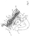
- a ball bar 1 which at its one free end a coupling ball 2 carries. At its second end, the ball bar 1 an angled, rectilinearly extending Bearing 3 on.
- This journal 3 is in one Housing 4 is received, which, as shown in FIG. 8, a cylindrical through hole 4.1 has. Therein is the likewise cylindrical bearing journal 3 to a rotatably mounted limited angle. Consequently can the ball rod 1 from a rest position into a Operating position or be pivoted vice versa, depending on Implementation of the vehicle for which the hitch is determined, the swing angle between 90 ° and 120 °.
- a bearing body 5 Fixed to the housing 4, possibly with it made in one piece, is a bearing body 5, which also a hollow cylindrical, recognizable in Fig. 8 Through hole 5.1 has.
- the limited Swing angle is here in the order of 50 °, what also from the installation conditions of the trailer hitch depends on the vehicle in question.
- the Installation position on the respective vehicle becomes the cylinder axis of the bearing body 5 in the vehicle longitudinal axis arranged.
- the differential gear 7 has a driven by the input shaft 6.2 Cage 8, in which planet gears 9 are mounted.
- the planet gears 9 mesh with a first bevel gear 10th and a second bevel gear 11, both on one Worm shaft 12 are arranged.
- the loose bevel gear 11 is fixedly connected to a first worm 13, the corresponding also loose on the worm shaft 12 sits.
- a second screw 14 which consequently the rotational movements the worm shaft 12 participates.
- the differential gear 7 is arranged in a housing 15, and close in the axial direction Housing parts 16 and 17 for the two screws 13 and 14 on.
- the housing 15 and the housing parts 16 and 17 are in the direction of a diametric plane of the worm shaft 12 divisible and mounted in the assembly with the Bearing body 5 connected.
- For the storage of the worm shaft 12 are in the housing 15 and in the housing parts 16 and 17 provided appropriate bearings in the drawing are not shown in detail.
- the bearing body 5 has axially projecting at one end a receptacle 18 on which a first worm wheel 19 is firmly recorded. With this worm wheel 19 the first, loosely mounted on the worm shaft 12 meshes Worm 13, during its rotation corresponding to the Bearing body 5 together with the housing 4 and the other Divide the hitch by the through the hole 5.1 passing axis is pivoted.
- To the Worm wheel 19 is an axial projection 20, the on its free front with a claw contour 21.1 is provided. This claw contour 21.1 points in the Direction of rotation effective stops 22 for a rotary drive and an axially increasing curve 23 for displacement of the bearing body 5.
- the claw contour 21.1 at the base 20 of the first worm wheel 19 cooperates with a claw contour 21.2, which is located on a dog clutch part 26, which axially opposite to the projection 20 on the first Worm wheel 19 is arranged.
- the claw contours 21.1 and 21.2 can in an axial Approach of the dog clutch part 26 and a link 29th be provided, which is a the displacement stroke of the bearing body 5 corresponding slope in the axial direction having.
- this backdrop 29 engages a guide pin 29.1, which in approach 20 on the first worm wheel 19 in Radial direction is arranged.
- the dog clutch part 26 rotatably attached to an axle 25, on which the Bearing body 5 is pivotally mounted. Accordingly occurs the axle 25 through the through hole 5.1 of the bearing body 5 through.
- the axle part 25 is the one Component over which the entire hitch is held on the vehicle in question, and accordingly the axle part 25 is preferably in the Longitudinal axis of the respective vehicle arranged.
- the stops 22 and 27 of the jaw contours 21.1 and 21.2 ensure that the bearing body 5 each only the aforementioned limited swivel angle on the Achsteil 25 is rotatable. Over the adjoining ones rising curves 23 and 24 of the jaw contours 21.1 and 21.2, the bearing body 5 in the direction of his Swivel axis on the axle 25 are moved. This happens in the operating position of the ball rod 1 Beginning of the retraction movement in one direction of displacement and at the end of the pivoting movement of the bearing body. 5 when extending the ball rod 1 in the other direction of displacement. This will lock the bearing body 5 causes in the operating position of the ball bar 1.
- the housing 4 for receiving the journal 3 on the Ball bar 1 points to the remote from the ball bar 1 End of an extended housing section 32, in which a second worm wheel 33 is arranged, which with the second, firmly on the worm shaft 12th arranged worm wheel 14 is engaged.
- Fig. 8 further illustrates, the second worm wheel 33 mounted on an axle body 39, on the end a radially projecting coupling flange 34th located.
- axle body 39 In assembled arrangement of the axle body 39 is coaxial firmly on the bearing pin 3 of the ball rod 1 and can with this not only turned but also in the axial direction of the journal 3 are moved. This happens when retracting the ball rod 1 from the operating position out at the beginning of the retraction movement and also when reaching the swung-out end position to obtain the locked operating position in opposite Shift direction.
- These are at the one End face of the second worm wheel 33 and the coupling flange 34 cooperating stops 37 and 38 provided, which in the two directions of rotation Rotational drive effect.
- a first positive connection part 41 in Shape of a recess provided at the circumference of the journal 3 is a corresponding positive connection part 42 in the form of a cam when aligned in the circumferential direction on the positive connection part 41st can dip into the housing 4 therein.
- This locking position in particular Figures 1 and 7.
- Fig. 4 it can be seen on the front side 40 of the Housing 4 still be provided a stop 41.1 to in the rest position of the ball bar 1, the bearing pin. 3 bring on the housing 4 in a predetermined end position can.
Applications Claiming Priority (2)
| Application Number | Priority Date | Filing Date | Title |
|---|---|---|---|
| DE10360245 | 2003-12-20 | ||
| DE10360245A DE10360245B4 (de) | 2003-12-20 | 2003-12-20 | Anhängekupplung für Personenkraftfahrzeuge |
Publications (2)
| Publication Number | Publication Date |
|---|---|
| EP1544003A1 true EP1544003A1 (fr) | 2005-06-22 |
| EP1544003B1 EP1544003B1 (fr) | 2006-11-08 |
Family
ID=34485563
Family Applications (1)
| Application Number | Title | Priority Date | Filing Date |
|---|---|---|---|
| EP04030203A Active EP1544003B1 (fr) | 2003-12-20 | 2004-12-20 | Dispositif d'attelage pour véhicules automobiles |
Country Status (3)
| Country | Link |
|---|---|
| EP (1) | EP1544003B1 (fr) |
| AT (1) | ATE344738T1 (fr) |
| DE (2) | DE10360245B4 (fr) |
Cited By (4)
| Publication number | Priority date | Publication date | Assignee | Title |
|---|---|---|---|---|
| EP1637363A1 (fr) * | 2004-09-20 | 2006-03-22 | Jaeger Cartronix GmbH | Dispositif d'entraînement manuel pour un attelage de remorque |
| EP1717067A1 (fr) * | 2005-04-26 | 2006-11-02 | Jaeger Cartronix GmbH | Dispositif d'entraînement pour un attelage de remorque |
| EP3736145A1 (fr) * | 2019-05-09 | 2020-11-11 | Brink Towing Systems B.V. | Agencement de crochet de remorquage rétractable |
| WO2024067801A1 (fr) * | 2022-09-29 | 2024-04-04 | 延锋国际汽车技术有限公司 | Dispositif de rotation d'attelage de remorque |
Families Citing this family (6)
| Publication number | Priority date | Publication date | Assignee | Title |
|---|---|---|---|---|
| DE102006008837A1 (de) * | 2006-02-27 | 2007-09-06 | Westfalia-Automotive Gmbh | Anhängerkupplung für Kraftfahrzeuge |
| DE202006011346U1 (de) * | 2006-07-20 | 2007-11-22 | Al-Ko Kober Ag | Schwenkbare Anhängevorrichtung für Zugfahrzeuge |
| DE102006035261A1 (de) † | 2006-07-29 | 2008-01-31 | Scambia Industrial Developments Aktiengesellschaft | Anhängekupplung |
| DE102014209727A1 (de) | 2013-05-31 | 2014-12-18 | Volkswagen Ag | Anhängevorrichtung für ein Zugfahrzeug |
| DE102015109411B4 (de) * | 2015-06-12 | 2017-02-16 | Ercan Mutlu | Anhängerkupplung für ein Kraftfahrzeug |
| EP4194232A1 (fr) * | 2021-12-10 | 2023-06-14 | Brink Towing Systems B.V. | Agencement de crochet de remorquage |
Citations (3)
| Publication number | Priority date | Publication date | Assignee | Title |
|---|---|---|---|---|
| EP1024036A1 (fr) * | 1999-01-21 | 2000-08-02 | ORIS FAHRZEUGTEILE HANS RIEHLE GmbH | Attelage de remorque |
| DE10023640A1 (de) | 2000-05-13 | 2001-11-15 | Fac Frank Abels Consult & Tech | Anhängerkupplung |
| WO2003072375A1 (fr) * | 2002-02-28 | 2003-09-04 | Al-Ko Kober Ag | Dispositif de remorquage pivotant pour vehicules de traction |
Family Cites Families (1)
| Publication number | Priority date | Publication date | Assignee | Title |
|---|---|---|---|---|
| DE2020327A1 (de) * | 1970-04-25 | 1971-11-11 | Sklarny Kavalier N P | Verfahren zur Erzeugung poroeser Gegenstaende durch Sintern |
-
2003
- 2003-12-20 DE DE10360245A patent/DE10360245B4/de not_active Expired - Fee Related
-
2004
- 2004-12-20 DE DE502004001946T patent/DE502004001946D1/de active Active
- 2004-12-20 AT AT04030203T patent/ATE344738T1/de not_active IP Right Cessation
- 2004-12-20 EP EP04030203A patent/EP1544003B1/fr active Active
Patent Citations (3)
| Publication number | Priority date | Publication date | Assignee | Title |
|---|---|---|---|---|
| EP1024036A1 (fr) * | 1999-01-21 | 2000-08-02 | ORIS FAHRZEUGTEILE HANS RIEHLE GmbH | Attelage de remorque |
| DE10023640A1 (de) | 2000-05-13 | 2001-11-15 | Fac Frank Abels Consult & Tech | Anhängerkupplung |
| WO2003072375A1 (fr) * | 2002-02-28 | 2003-09-04 | Al-Ko Kober Ag | Dispositif de remorquage pivotant pour vehicules de traction |
Cited By (4)
| Publication number | Priority date | Publication date | Assignee | Title |
|---|---|---|---|---|
| EP1637363A1 (fr) * | 2004-09-20 | 2006-03-22 | Jaeger Cartronix GmbH | Dispositif d'entraînement manuel pour un attelage de remorque |
| EP1717067A1 (fr) * | 2005-04-26 | 2006-11-02 | Jaeger Cartronix GmbH | Dispositif d'entraînement pour un attelage de remorque |
| EP3736145A1 (fr) * | 2019-05-09 | 2020-11-11 | Brink Towing Systems B.V. | Agencement de crochet de remorquage rétractable |
| WO2024067801A1 (fr) * | 2022-09-29 | 2024-04-04 | 延锋国际汽车技术有限公司 | Dispositif de rotation d'attelage de remorque |
Also Published As
| Publication number | Publication date |
|---|---|
| DE502004001946D1 (de) | 2006-12-21 |
| DE10360245B4 (de) | 2006-04-20 |
| DE10360245A1 (de) | 2005-07-21 |
| ATE344738T1 (de) | 2006-11-15 |
| EP1544003B1 (fr) | 2006-11-08 |
Similar Documents
| Publication | Publication Date | Title |
|---|---|---|
| EP0850147B2 (fr) | Dispositif d'attelage de remorque pour vehicules automobiles | |
| DE19858978C5 (de) | Schwenkbare Anhängerkupplung für Kraftfahrzeuge | |
| DE102005007430A1 (de) | Befestigungs- und Positioniervorrichtung für einen Fahrzeugsitz | |
| DE10392415T5 (de) | Elektrische Lenkradschlossvorrichtung | |
| DE202006011346U1 (de) | Schwenkbare Anhängevorrichtung für Zugfahrzeuge | |
| DE102010027826A1 (de) | Parksperre für ein Kraftfahrzeug | |
| EP1544003B1 (fr) | Dispositif d'attelage pour véhicules automobiles | |
| EP1722050A1 (fr) | Serrure à verrou rotatif | |
| DE102004061487B4 (de) | Motor-getriebene Lenkradschlosseinrichtung | |
| DE4326291C2 (de) | Fahrzeugdach | |
| DE102004045869A1 (de) | Anhängerkupplung | |
| DE102009045290A1 (de) | Taumelkugelgelenk | |
| EP1084870A2 (fr) | Dispositif d'attelage articulé à verrouillage automatique | |
| DE10347817B4 (de) | Anhängekupplung | |
| DE4040372C2 (de) | Automatische Öffnungs- und Schließvorrichtung für eine Heckklappe | |
| EP2497701A1 (fr) | Plateforme pivotante pour un véhicule articulé | |
| EP2428381B1 (fr) | Dispositif de verrouillage | |
| DE19605570A1 (de) | Anhängerkupplung für Kraftfahrzeuge | |
| WO2008049569A1 (fr) | Dispositif d'attelage | |
| DE10347816B4 (de) | Anhängekupplung mit lastfreier Drehlagereinrichtung | |
| EP0823342B1 (fr) | Attelage de remorque | |
| EP0844208A1 (fr) | Cric de véhicule | |
| EP2671739A2 (fr) | Système d'actionnement pour un attelage de véhicule automobile | |
| DE102019128563A1 (de) | Elektromechanischer Parksperrenaktuator | |
| DE102010030828A1 (de) | Anhängevorrichtung für ein Fahrzeug |
Legal Events
| Date | Code | Title | Description |
|---|---|---|---|
| PUAI | Public reference made under article 153(3) epc to a published international application that has entered the european phase |
Free format text: ORIGINAL CODE: 0009012 |
|
| AK | Designated contracting states |
Kind code of ref document: A1 Designated state(s): AT BE BG CH CY CZ DE DK EE ES FI FR GB GR HU IE IS IT LI LT LU MC NL PL PT RO SE SI SK TR |
|
| AX | Request for extension of the european patent |
Extension state: AL BA HR LV MK YU |
|
| 17P | Request for examination filed |
Effective date: 20050524 |
|
| AKX | Designation fees paid |
Designated state(s): AT BE BG CH CY CZ DE DK EE ES FI FR GB GR HU IE IS IT LI LT LU MC NL PL PT RO SE SI SK TR |
|
| GRAP | Despatch of communication of intention to grant a patent |
Free format text: ORIGINAL CODE: EPIDOSNIGR1 |
|
| GRAS | Grant fee paid |
Free format text: ORIGINAL CODE: EPIDOSNIGR3 |
|
| GRAA | (expected) grant |
Free format text: ORIGINAL CODE: 0009210 |
|
| AK | Designated contracting states |
Kind code of ref document: B1 Designated state(s): AT BE BG CH CY CZ DE DK EE ES FI FR GB GR HU IE IS IT LI LT LU MC NL PL PT RO SE SI SK TR |
|
| PG25 | Lapsed in a contracting state [announced via postgrant information from national office to epo] |
Ref country code: IT Free format text: LAPSE BECAUSE OF FAILURE TO SUBMIT A TRANSLATION OF THE DESCRIPTION OR TO PAY THE FEE WITHIN THE PRESCRIBED TIME-LIMIT;WARNING: LAPSES OF ITALIAN PATENTS WITH EFFECTIVE DATE BEFORE 2007 MAY HAVE OCCURRED AT ANY TIME BEFORE 2007. THE CORRECT EFFECTIVE DATE MAY BE DIFFERENT FROM THE ONE RECORDED. Effective date: 20061108 Ref country code: CZ Free format text: LAPSE BECAUSE OF FAILURE TO SUBMIT A TRANSLATION OF THE DESCRIPTION OR TO PAY THE FEE WITHIN THE PRESCRIBED TIME-LIMIT Effective date: 20061108 Ref country code: IE Free format text: LAPSE BECAUSE OF FAILURE TO SUBMIT A TRANSLATION OF THE DESCRIPTION OR TO PAY THE FEE WITHIN THE PRESCRIBED TIME-LIMIT Effective date: 20061108 Ref country code: SK Free format text: LAPSE BECAUSE OF FAILURE TO SUBMIT A TRANSLATION OF THE DESCRIPTION OR TO PAY THE FEE WITHIN THE PRESCRIBED TIME-LIMIT Effective date: 20061108 Ref country code: SI Free format text: LAPSE BECAUSE OF FAILURE TO SUBMIT A TRANSLATION OF THE DESCRIPTION OR TO PAY THE FEE WITHIN THE PRESCRIBED TIME-LIMIT Effective date: 20061108 Ref country code: NL Free format text: LAPSE BECAUSE OF FAILURE TO SUBMIT A TRANSLATION OF THE DESCRIPTION OR TO PAY THE FEE WITHIN THE PRESCRIBED TIME-LIMIT Effective date: 20061108 Ref country code: FI Free format text: LAPSE BECAUSE OF FAILURE TO SUBMIT A TRANSLATION OF THE DESCRIPTION OR TO PAY THE FEE WITHIN THE PRESCRIBED TIME-LIMIT Effective date: 20061108 Ref country code: RO Free format text: LAPSE BECAUSE OF FAILURE TO SUBMIT A TRANSLATION OF THE DESCRIPTION OR TO PAY THE FEE WITHIN THE PRESCRIBED TIME-LIMIT Effective date: 20061108 Ref country code: PL Free format text: LAPSE BECAUSE OF FAILURE TO SUBMIT A TRANSLATION OF THE DESCRIPTION OR TO PAY THE FEE WITHIN THE PRESCRIBED TIME-LIMIT Effective date: 20061108 |
|
| REG | Reference to a national code |
Ref country code: GB Ref legal event code: FG4D Free format text: NOT ENGLISH |
|
| RAP2 | Party data changed (patent owner data changed or rights of a patent transferred) |
Owner name: WESTFALIA - AUTOMOTIVE GMBH |
|
| REG | Reference to a national code |
Ref country code: CH Ref legal event code: EP |
|
| REG | Reference to a national code |
Ref country code: IE Ref legal event code: FG4D Free format text: LANGUAGE OF EP DOCUMENT: GERMAN |
|
| REF | Corresponds to: |
Ref document number: 502004001946 Country of ref document: DE Date of ref document: 20061221 Kind code of ref document: P |
|
| PG25 | Lapsed in a contracting state [announced via postgrant information from national office to epo] |
Ref country code: BE Free format text: LAPSE BECAUSE OF NON-PAYMENT OF DUE FEES Effective date: 20061231 Ref country code: MC Free format text: LAPSE BECAUSE OF NON-PAYMENT OF DUE FEES Effective date: 20061231 |
|
| NLT2 | Nl: modifications (of names), taken from the european patent patent bulletin |
Owner name: WESTFALIA - AUTOMOTIVE GMBH Effective date: 20061122 |
|
| PG25 | Lapsed in a contracting state [announced via postgrant information from national office to epo] |
Ref country code: BG Free format text: LAPSE BECAUSE OF FAILURE TO SUBMIT A TRANSLATION OF THE DESCRIPTION OR TO PAY THE FEE WITHIN THE PRESCRIBED TIME-LIMIT Effective date: 20070208 Ref country code: DK Free format text: LAPSE BECAUSE OF FAILURE TO SUBMIT A TRANSLATION OF THE DESCRIPTION OR TO PAY THE FEE WITHIN THE PRESCRIBED TIME-LIMIT Effective date: 20070208 Ref country code: SE Free format text: LAPSE BECAUSE OF FAILURE TO SUBMIT A TRANSLATION OF THE DESCRIPTION OR TO PAY THE FEE WITHIN THE PRESCRIBED TIME-LIMIT Effective date: 20070208 |
|
| PG25 | Lapsed in a contracting state [announced via postgrant information from national office to epo] |
Ref country code: ES Free format text: LAPSE BECAUSE OF FAILURE TO SUBMIT A TRANSLATION OF THE DESCRIPTION OR TO PAY THE FEE WITHIN THE PRESCRIBED TIME-LIMIT Effective date: 20070219 |
|
| PG25 | Lapsed in a contracting state [announced via postgrant information from national office to epo] |
Ref country code: IS Free format text: LAPSE BECAUSE OF FAILURE TO SUBMIT A TRANSLATION OF THE DESCRIPTION OR TO PAY THE FEE WITHIN THE PRESCRIBED TIME-LIMIT Effective date: 20070308 |
|
| PG25 | Lapsed in a contracting state [announced via postgrant information from national office to epo] |
Ref country code: PT Free format text: LAPSE BECAUSE OF FAILURE TO SUBMIT A TRANSLATION OF THE DESCRIPTION OR TO PAY THE FEE WITHIN THE PRESCRIBED TIME-LIMIT Effective date: 20070409 |
|
| ET | Fr: translation filed | ||
| NLV1 | Nl: lapsed or annulled due to failure to fulfill the requirements of art. 29p and 29m of the patents act | ||
| GBV | Gb: ep patent (uk) treated as always having been void in accordance with gb section 77(7)/1977 [no translation filed] |
Effective date: 20061108 |
|
| REG | Reference to a national code |
Ref country code: IE Ref legal event code: FD4D |
|
| PLBE | No opposition filed within time limit |
Free format text: ORIGINAL CODE: 0009261 |
|
| STAA | Information on the status of an ep patent application or granted ep patent |
Free format text: STATUS: NO OPPOSITION FILED WITHIN TIME LIMIT |
|
| 26N | No opposition filed |
Effective date: 20070809 |
|
| PG25 | Lapsed in a contracting state [announced via postgrant information from national office to epo] |
Ref country code: GB Free format text: LAPSE BECAUSE OF FAILURE TO SUBMIT A TRANSLATION OF THE DESCRIPTION OR TO PAY THE FEE WITHIN THE PRESCRIBED TIME-LIMIT Effective date: 20061108 |
|
| BERE | Be: lapsed |
Owner name: WESTFALIA-AUTOMOTIVE G.M.B.H. & CO. KG Effective date: 20061231 |
|
| PG25 | Lapsed in a contracting state [announced via postgrant information from national office to epo] |
Ref country code: AT Free format text: LAPSE BECAUSE OF NON-PAYMENT OF DUE FEES Effective date: 20061220 |
|
| PG25 | Lapsed in a contracting state [announced via postgrant information from national office to epo] |
Ref country code: GR Free format text: LAPSE BECAUSE OF FAILURE TO SUBMIT A TRANSLATION OF THE DESCRIPTION OR TO PAY THE FEE WITHIN THE PRESCRIBED TIME-LIMIT Effective date: 20070209 |
|
| PG25 | Lapsed in a contracting state [announced via postgrant information from national office to epo] |
Ref country code: EE Free format text: LAPSE BECAUSE OF FAILURE TO SUBMIT A TRANSLATION OF THE DESCRIPTION OR TO PAY THE FEE WITHIN THE PRESCRIBED TIME-LIMIT Effective date: 20061108 |
|
| PG25 | Lapsed in a contracting state [announced via postgrant information from national office to epo] |
Ref country code: HU Free format text: LAPSE BECAUSE OF FAILURE TO SUBMIT A TRANSLATION OF THE DESCRIPTION OR TO PAY THE FEE WITHIN THE PRESCRIBED TIME-LIMIT Effective date: 20070509 Ref country code: LU Free format text: LAPSE BECAUSE OF NON-PAYMENT OF DUE FEES Effective date: 20061220 Ref country code: LT Free format text: LAPSE BECAUSE OF FAILURE TO SUBMIT A TRANSLATION OF THE DESCRIPTION OR TO PAY THE FEE WITHIN THE PRESCRIBED TIME-LIMIT Effective date: 20061108 Ref country code: TR Free format text: LAPSE BECAUSE OF FAILURE TO SUBMIT A TRANSLATION OF THE DESCRIPTION OR TO PAY THE FEE WITHIN THE PRESCRIBED TIME-LIMIT Effective date: 20061108 |
|
| PG25 | Lapsed in a contracting state [announced via postgrant information from national office to epo] |
Ref country code: CY Free format text: LAPSE BECAUSE OF FAILURE TO SUBMIT A TRANSLATION OF THE DESCRIPTION OR TO PAY THE FEE WITHIN THE PRESCRIBED TIME-LIMIT Effective date: 20061108 |
|
| REG | Reference to a national code |
Ref country code: CH Ref legal event code: PL |
|
| PG25 | Lapsed in a contracting state [announced via postgrant information from national office to epo] |
Ref country code: CH Free format text: LAPSE BECAUSE OF NON-PAYMENT OF DUE FEES Effective date: 20081231 Ref country code: LI Free format text: LAPSE BECAUSE OF NON-PAYMENT OF DUE FEES Effective date: 20081231 |
|
| REG | Reference to a national code |
Ref country code: FR Ref legal event code: PLFP Year of fee payment: 12 |
|
| REG | Reference to a national code |
Ref country code: FR Ref legal event code: PLFP Year of fee payment: 13 |
|
| REG | Reference to a national code |
Ref country code: FR Ref legal event code: PLFP Year of fee payment: 14 |
|
| PGFP | Annual fee paid to national office [announced via postgrant information from national office to epo] |
Ref country code: FR Payment date: 20211220 Year of fee payment: 18 |
|
| PG25 | Lapsed in a contracting state [announced via postgrant information from national office to epo] |
Ref country code: FR Free format text: LAPSE BECAUSE OF NON-PAYMENT OF DUE FEES Effective date: 20221231 |
|
| PGFP | Annual fee paid to national office [announced via postgrant information from national office to epo] |
Ref country code: DE Payment date: 20231208 Year of fee payment: 20 |