EP1543971B1 - Flüssigkeitsausstoss-verfahren und -vorrichtung - Google Patents
Flüssigkeitsausstoss-verfahren und -vorrichtung Download PDFInfo
- Publication number
- EP1543971B1 EP1543971B1 EP04257761A EP04257761A EP1543971B1 EP 1543971 B1 EP1543971 B1 EP 1543971B1 EP 04257761 A EP04257761 A EP 04257761A EP 04257761 A EP04257761 A EP 04257761A EP 1543971 B1 EP1543971 B1 EP 1543971B1
- Authority
- EP
- European Patent Office
- Prior art keywords
- liquid
- liquid chamber
- volume
- recording
- column
- Prior art date
- Legal status (The legal status is an assumption and is not a legal conclusion. Google has not performed a legal analysis and makes no representation as to the accuracy of the status listed.)
- Expired - Lifetime
Links
- 239000007788 liquid Substances 0.000 title claims description 301
- 238000000034 method Methods 0.000 title claims description 77
- 230000008602 contraction Effects 0.000 claims description 22
- 239000012530 fluid Substances 0.000 claims 2
- 239000000976 ink Substances 0.000 description 45
- 230000000052 comparative effect Effects 0.000 description 19
- 230000005499 meniscus Effects 0.000 description 8
- 238000006073 displacement reaction Methods 0.000 description 6
- 238000000059 patterning Methods 0.000 description 4
- 230000000694 effects Effects 0.000 description 3
- 238000010422 painting Methods 0.000 description 3
- 238000007639 printing Methods 0.000 description 3
- 239000004744 fabric Substances 0.000 description 2
- 238000011084 recovery Methods 0.000 description 2
- -1 board Substances 0.000 description 1
- 230000001419 dependent effect Effects 0.000 description 1
- 238000007599 discharging Methods 0.000 description 1
- 238000005516 engineering process Methods 0.000 description 1
- 239000010985 leather Substances 0.000 description 1
- 238000004519 manufacturing process Methods 0.000 description 1
- 230000003287 optical effect Effects 0.000 description 1
- 239000000123 paper Substances 0.000 description 1
- 239000007787 solid Substances 0.000 description 1
- 230000000087 stabilizing effect Effects 0.000 description 1
- 239000000758 substrate Substances 0.000 description 1
Images



Classifications
-
- B—PERFORMING OPERATIONS; TRANSPORTING
- B41—PRINTING; LINING MACHINES; TYPEWRITERS; STAMPS
- B41J—TYPEWRITERS; SELECTIVE PRINTING MECHANISMS, i.e. MECHANISMS PRINTING OTHERWISE THAN FROM A FORME; CORRECTION OF TYPOGRAPHICAL ERRORS
- B41J2/00—Typewriters or selective printing mechanisms characterised by the printing or marking process for which they are designed
- B41J2/005—Typewriters or selective printing mechanisms characterised by the printing or marking process for which they are designed characterised by bringing liquid or particles selectively into contact with a printing material
- B41J2/01—Ink jet
- B41J2/015—Ink jet characterised by the jet generation process
- B41J2/04—Ink jet characterised by the jet generation process generating single droplets or particles on demand
- B41J2/045—Ink jet characterised by the jet generation process generating single droplets or particles on demand by pressure, e.g. electromechanical transducers
-
- B—PERFORMING OPERATIONS; TRANSPORTING
- B41—PRINTING; LINING MACHINES; TYPEWRITERS; STAMPS
- B41J—TYPEWRITERS; SELECTIVE PRINTING MECHANISMS, i.e. MECHANISMS PRINTING OTHERWISE THAN FROM A FORME; CORRECTION OF TYPOGRAPHICAL ERRORS
- B41J2/00—Typewriters or selective printing mechanisms characterised by the printing or marking process for which they are designed
- B41J2/005—Typewriters or selective printing mechanisms characterised by the printing or marking process for which they are designed characterised by bringing liquid or particles selectively into contact with a printing material
- B41J2/01—Ink jet
- B41J2/015—Ink jet characterised by the jet generation process
- B41J2/04—Ink jet characterised by the jet generation process generating single droplets or particles on demand
- B41J2/045—Ink jet characterised by the jet generation process generating single droplets or particles on demand by pressure, e.g. electromechanical transducers
- B41J2/04501—Control methods or devices therefor, e.g. driver circuits, control circuits
- B41J2/04581—Control methods or devices therefor, e.g. driver circuits, control circuits controlling heads based on piezoelectric elements
-
- B—PERFORMING OPERATIONS; TRANSPORTING
- B41—PRINTING; LINING MACHINES; TYPEWRITERS; STAMPS
- B41J—TYPEWRITERS; SELECTIVE PRINTING MECHANISMS, i.e. MECHANISMS PRINTING OTHERWISE THAN FROM A FORME; CORRECTION OF TYPOGRAPHICAL ERRORS
- B41J2/00—Typewriters or selective printing mechanisms characterised by the printing or marking process for which they are designed
- B41J2/005—Typewriters or selective printing mechanisms characterised by the printing or marking process for which they are designed characterised by bringing liquid or particles selectively into contact with a printing material
- B41J2/01—Ink jet
- B41J2/015—Ink jet characterised by the jet generation process
- B41J2/04—Ink jet characterised by the jet generation process generating single droplets or particles on demand
- B41J2/045—Ink jet characterised by the jet generation process generating single droplets or particles on demand by pressure, e.g. electromechanical transducers
- B41J2/04501—Control methods or devices therefor, e.g. driver circuits, control circuits
- B41J2/04588—Control methods or devices therefor, e.g. driver circuits, control circuits using a specific waveform
Definitions
- the present invention relates to a liquid ejecting method which is for a liquid ejecting apparatus comprising: a plurality of liquid ejection orifices, a plurality of liquid chambers connected to the plurality of liquid ejection orifices, one for one, and a plurality of liquid chamber volume controlling means which are integral parts of the plurality of liquid chambers, one for one, and which cause the liquid ejecting apparatus to eject liquid, by changing the volume of each liquid chamber by the liquid volume controlling means.
- the present invention also relates to a liquid ejecting apparatus compatible with such a liquid ejecting method.
- the liquid ejecting method and liquid ejecting apparatus in accordance with the present invention are applicable to various liquid ejecting apparatuses, for example, an ink jet recording apparatus, a device for printing on paper, fabric, leather, unwoven fabric, OHP, etc., a patterning apparatus or painting apparatus for adhering liquid to substrate, board, solid objects, etc., which are required to eject very minute liquid droplets while being highly accurate in terms of the location at which the liquid droplets land.
- An ink jet recording apparatus has been widely used as the recording apparatus for a printer, a facsimile, etc., because it is low in noise, low in operational cost, small in size, and easily enabled to form color images. Further, in recent years, its usage has been spreading in the device manufacturing field, in which it is used as a patterning apparatus.
- the recording head In the majority of ink jet recording apparatuses, the recording head is moved in the primary scanning direction while it is ejecting liquid droplets. It is possible, however, to structure an ink jet recording apparatus so that the recording head remains stationary while a recording medium is moved. It can be assumed that the above described structural arrangements are applicable to a patterning apparatus, a painting apparatus, etc.
- the ink jet recording apparatus disclosed in Japanese Laid ⁇ Open Patent Application Hei 6-268928 is provided with a liquid ejection head having a plurality of pressure generation chambers connected to a plurality of nozzles, one for one, and a plurality of piezoelectric elements for pressurizing the pressure generation chambers, one for one. It is structured so that it can repeatedly and rapidly form liquid droplets while stabilizing its recording head in terms of the meniscus position at the point of ejection by controlling the waveform of the voltage for compressing or decompressing the piezoelectric element with the use of a driver circuit.
- recording gap a complex flow of air is generated through the gap (which hereinafter will be referred to as "recording gap" between the recording head and recording medium.
- a recording head has been continuously reduced in liquid droplet size.
- a recording head has been continuously reduced in liquid column size.
- the liquid droplets yielded from a liquid column angled relative to the predetermined direction in which liquid is to be ejected, are different in the point at which their flight begins. Therefore, they are destined to be different in the landing point.
- European patent application no. EP-A-1 004 441 discloses an ink jet printer having a pressure generation chamber which is expanded in a stepped manner to effect high-speed discharge of a very small ink droplet. Prior to the ink discharge, the pressure generation chamber is contracted to enable high-accuracy gradation printing.
- a control unit generates: a first contraction signal for contracting the pressure generation chamber without discharging any ink droplet; a first expansion signal for expanding the pressure generation chamber to discharge an ink droplet, and a second expansion signal to further expand the pressure generation chamber to break off an ink column discharged from a nozzle.
- An embodiment of the present invention provides a combination of a liquid ejecting method, and an apparatus compatible with the liquid ejecting method, which minimizes the effect of the air flow in the recording gap by reducing the length by which liquid is extruded in the form of a column from a liquid ejection head, so that minute liquid droplets are ejected at a high level of landing accuracy.
- a liquid ejecting method as defined in claim 1.
- the length of the time it takes for the body of liquid extruded from the liquid ejection head to break into a plurality liquid droplets can be reduced by minimizing the length, by which the body of liquid is extruded, in the form of a column, from the liquid ejection head, by severing the body of liquid having been extruded in the form of a column, from the body of liquid in the liquid ejection head, by pulling the body of liquid in the liquid ejection head in the direction opposite to the direction (outward direction) in which the body of liquid is being extruded in the form of a column. Therefore, the effect of the air flow in the recording gap upon the body of liquid being extruded in the form of a column is minimized, making it therefore possible to eject minute liquid droplets at a high level of landing accuracy.
- FIG. 1 is a schematic perspective view of a typical ink jet recording apparatus compatible with the liquid ejecting method in accordance with the present invention.
- a recording medium P As shown in Figure 1 , as a recording medium P is inserted into the ink jet recording apparatus, it is conveyed by a pair of conveying rollers 109 and 110 to the area in which recording can be made by the recording head unit 100.
- the recording head unit 100 is supported by a pair of guiding shafts 107 and 108, being enabled to be reciprocally moved along the guiding shafts 107 and 108 in the direction (primary scanning direction) parallel to the direction in which the guiding shafts 107 and 108 extend.
- the direction in which the recording head unit is reciprocally movable is the primary scanning direction, and the direction in which the recording medium P is conveyed is the secondary scanning direction.
- the recording head unit 100 has a plurality of recording heads for ejecting, in the form of a liquid droplet, a plurality of inks different in color, and a plurality of ink containers for supplying the recording heads with the plurality of inks different in color, one for one.
- the number of inks, different in color, ejected by the ink jet recording apparatus is four; the four inks are black (Bk), cyan (C), magenta (M), and yellow (Y) inks.
- the order in which the plurality of ink containers are arranged is optional.
- the recovery unit 112 cleans the ejection orifices of the recording head to restore the performance of the recording head when the recording head is not in operation.
- the recording head unit 100 and the black (Bk), cyan (C), magenta (M), yellow (Y) ink containers are structured so that the ink containers can be replaced independently from each other.
- a group of recording heads for ejecting Bk ink droplets, C ink droplets, M ink droplets, and Y ink droplets one for one, an ink container 101B for Bk ink, an ink container 101C for C ink, an ink container 101M for M ink, and an ink container 101Y for Y ink, are mounted.
- the ink containers are connected to the corresponding ink jet recording heads, one for one, supplying thereby the inks into the ink passages (nozzles) leading to the ejection orifices of the group of recording heads.
- the structures of the recording head unit 100 and ink containers do not need to be limited to the above described structures.
- the ink containers 101B, 101C, 101M, and 101Y may be integrated in optional combinations.
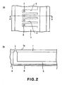
- the liquid ejection head in accordance with the present invention comprises: an orifice plate 1 having a plurality of ejection orifices 2, and a plurality of liquid chambers 5 for storing liquid, and a plurality of liquid chamber volume controlling means 6 having a piezoelectric element.
- the plurality of liquid chambers 5 are connected to the plurality of ejection orifices 2 one for one.
- the plurality of liquid chamber volume controlling means 6 are disposed in the plurality of liquid chambers 5, one for one.
- driving signals in accordance with recording data are applied to the liquid chamber volume controlling means 6 from a driver circuit (unshown), liquid droplets are ejected from the ejection orifices 2.
- the time when the tip of the liquid column 3 emerges outward past the plane of the external surface 1a of the orifice plate 1 can be detected with the use of a CCD camera or the like, by projecting a pulsing beam of light onto the ejection orifice 2 with the use of a strobe, an LED, a laser, or the like.
- Figures 3 - 5 are schematic sectional views of one of the liquid ejection orifices 2 and its adjacencies, showing, following the time line, how the liquid column 3 forms and turns into multiple droplets. It should be noted here that the number of the liquid droplets into which the liquid column 3 breaks, varies; it is not limited to the number in Figures 3 - 5 .
- the speed of a vibration plate 4 is measured with the use of a laser trap vibrometer, with no contact.
- the liquid column 3 emerges, with its "R” portion remaining in contact with the edge 2a of the opening of the ejection orifice 2 as shown in Figure 4(a) , or with its "R” portion having no contact with the edge 2a of the opening of the ejection orifice 2 as shown in Figure 5(a) .
- the liquid column 3 begins to be subjected to the air flow formed in the recording gap.
- the process of severing the liquid column 3 by expanding the liquid chamber 5 begins.
- the liquid column 3 severs from the body of liquid in the liquid ejection nozzle and flies away while breaking into a plurality of liquid droplets, which continue to fly.
- a liquid ejection head similar to the one shown in Figure 2 (which does not show common liquid chamber) was produced.
- the recording gap was 1.5 mm.
- Dots were formed on a coated paper of high quality by driving the representative nozzles at 15 kHz.
- each dot on the coated paper of high quality revealed that each dot was formed of three liquid droplets which landed in a partially overlapping manner.
- the liquid ejection head in this embodiment is similar to the one shown in Figure 2 .
- the recording gap was 1.5 mm, and dots were formed on a piece of coated paper of high quality by driving the representative nozzles at 15 kHz.
- each dot on the coated paper of high quality revealed that unlike the dots in the first comparative case, the dots formed by the recording head in this embodiment were almost perfectly circular, that is, so close to being perfectly circular that it was virtually impossible to detect that each dot was formed of a plurality of liquid droplets.
- the liquid ejection head glided in the primary scanning direction (X direction) as shown in Figure 3 , and therefore, the air in the recording gap flowed, relative to the liquid ejection head, in the direction opposite to the X direction.
- the liquid column 3 projected into the recording gap by a distance substantially shorter than the distance by which the liquid column 3 projected in first comparative case.
- the angle of ⁇ ( Figure 6 ) by which the liquid column 3 was tilted in this embodiment was extremely small.
- the liquid ejection head in this second embodiment is similar in structure to the one shown in Figure 2 .
- the recording gap was 1.5 mm, and dots were formed on a piece of coated paper of high quality by driving the representative nozzles at 15 kHz, under the same conditions as those in the first embodiment.
- each dot on the coated paper of high quality revealed that the dots formed by the recording head in this embodiment were almost perfectly circular, that is, so close to being perfectly circular that it was virtually impossible to detect that each dot was formed of a plurality of liquid droplets, as those formed by the liquid ejection head in the first embodiment.
- the liquid ejection head glided in the primary scanning direction (X direction), and therefore, the air in the recording gap flowed, relative to the liquid ejection head, in the direction opposite to the X direction.
- the liquid column 3 projected into the recording gap by a distance substantially shorter than the distance by which the liquid column 3 was projected in the first comparative case.
- the recording gap was 1.5 mm, and dots were formed on a piece of coated paper of high quality by driving the representative nozzles at 15 kHz, under the same conditions as those in the second embodiment.
- each dot on the coated paper of high quality revealed that the dots formed by the recording head in this embodiment were almost perfectly circular, that is, so close to being perfectly circular that it was virtually impossible to detect that each dot was formed of a plurality of liquid droplets, as those formed by the liquid ejection head in the first embodiment.
- the liquid ejection head glided in the primary scanning direction (X direction), and therefore, the air in the recording gap flowed, relative to the liquid ejection head, in the direction opposite to the X direction.
- the liquid column 3 projected into the recording gap by a distance substantially shorter than the distance by which the liquid column 3 was projected in the first comparative case.
- the auxiliary contraction process is a process in which each liquid chamber is contracted, reducing thereby its volume, by an amount insufficient for liquid ejection.
- the auxiliary contraction process has the drawback of prolonging each ejection cycle.
- it has the merit of increasing the distance by which the meniscus can be pulled back within the limited control range (sum of meniscus displacement by contraction process and meniscus displacement by expansion process) of the liquid chamber volume controlling means 6.
- the recording gap was 1.5 mm, and dots were formed on a piece of coated paper of high quality by driving the representative nozzles at 15 kHz, under the same conditions as those in the first comparative case.
- each dot on the coated paper of high quality revealed that unlike the dots formed by the liquid ejection in the first comparative case, the dots formed by the liquid ejection head in this embodiment were almost perfectly circular, that is, so close to being perfectly circular that it was virtually impossible to detect that each dot was formed of a plurality of liquid droplets.
- the liquid ejection head glided in the primary scanning direction (X direction), and therefore, the air in the recording gap flew, relative to the liquid ejection head, in the direction opposite to the X direction.
- the liquid column 3 projected into the recording gap by a distance substantially shorter than the distance by which the liquid column 3 projected in the first comparative case.
- a liquid ejection head smaller in ejection orifice diameter than the one in the above described first comparative case (common liquid chamber is not shown) was produced.
- the recording gap was 1.5 mm.
- Dots were formed on a coated paper of high quality by driving the representative nozzles at 15 kHz.
- each dot on the coated paper of high quality revealed that each dot was formed of a minimum of three liquid droplets which landed in a partially overlapping manner.
- the tilted liquid column 303 broke into three liquid droplets or so, in such a manner that in terms of the primary scanning direction, there were an initial distance of ⁇ 1 between the center of the primary droplet 307 and that of the first satellite droplet 308, an initial distance of ⁇ 2 between the center of the primary droplet 307 and that of the second satellite droplet 309, and so on. Then, these liquid droplets flew while maintaining the above described distances, and landed on the coated paper. This is thought to be why each dots appeared as described above.
- the recording gap was 1.5 mm, and dots were formed on a piece of coated paper of high quality by driving the representative nozzles at 15 kHz, under the same conditions as those under which the liquid ejection head in the second comparative case was driven.
- each dot on the coated paper of high quality revealed that unlike the dots formed by the liquid ejection head in second comparative case, the dots formed by the recording head in this embodiment were almost perfectly circular, that is, so close to being perfectly circular that it was virtually impossible to detect that each dot was formed of a plurality of liquid droplets.
- the liquid ejection head glided in the primary scanning direction (X direction), and therefore, the air in the recording gap flowed, relative to the liquid ejection head, in the direction opposite to the X direction.
- the liquid column 3 projected into the recording gap by a distance substantially shorter than the distance by which the liquid column 3 projected from the liquid ejection head in the second comparative case.
- the liquid ejection head in this sixth embodiment is the same in structure as that in the fifth embodiment.
- the recording gap was 1.5 mm, and dots were formed on a piece of coated paper of high quality by driving the representative nozzles at 15 kHz, under the same conditions as those in the first embodiment.
- each dot on the coated paper of high quality revealed that the dots formed by the recording head in this embodiment were almost perfectly circular, that is, so close to being perfectly circular that it was virtually impossible to detect that each dot was formed of a plurality of liquid droplets, as those formed by the liquid ejection head in the fifth embodiment.
- the liquid ejection head glided in the primary scanning direction (X direction), and therefore, the air in the recording gap flowed, relative to the liquid ejection head, in the direction opposite to the X direction.
- the liquid column 3 projected into the recording gap by a distance substantially shorter than the distance by which the liquid column 303 was extruded by the liquid ejection head in the second comparative case.
- the liquid ejection head in this seventh embodiment is the same in structure as that in the sixth embodiment.
- the recording gap was 1.5 mm, and dots were formed on a piece of coated paper of high quality by driving the representative nozzles at 15 kHz, under the same conditions as those in the second embodiment.
- each dot on the coated paper of high quality revealed that the dots formed by the recording head in this embodiment were almost perfectly circular, that is, so close to being perfectly circular that it was virtually impossible to detect that each dot was formed of a plurality of liquid droplets, as those formed by the liquid ejection head in the sixth embodiment.
- the liquid ejection head glided in the primary scanning direction (X direction), and therefore, the air in the recording gap flowed, relative to the liquid ejection head, in the direction opposite to the X direction.
- the liquid column 3 was extruded into the recording gap by a distance substantially shorter than the distance by which the liquid column 303 was extruded by the liquid ejection head in the second comparative case.
- the angle of ⁇ Figure 6
- the liquid ejection head in the eighth embodiment was the same in structure as the second comparative sample of a liquid ejection head.
- the auxiliary contraction process by the liquid chamber volume controlling means 6 was started.
- the auxiliary contraction process is a process in which each liquid chamber is contracted, reducing thereby its volume, by an amount insufficient for liquid ejection. To include this process in each ejection cycle has the drawback of prolonging each ejection cycle.
- the recording gap was 1.5 mm, and dots were formed on a piece of coated paper of high quality by driving the representative nozzles at 15 kHz, under the same conditions as those under which the liquid ejection head in the first comparative case was driven.
- each dot on the coated paper of high quality revealed that unlike the dots formed by the liquid ejection head in the second comparative case, the dots formed by the liquid ejection head in this embodiment were almost perfectly circular, that is, so close to being perfectly circular that it was virtually impossible to detect that each dot was formed of a plurality of liquid droplets.
- the liquid ejection head glided in the primary scanning direction (X direction), and therefore, the air in the recording gap flew, relative to the liquid ejection head, in the direction opposite to the X direction.
- the liquid column 3 was extruded into the recording gap by a distance substantially shorter than the distance by which the liquid column 303 was extruded by the liquid ejection head in the second comparative embodiment. This is thought to be why the angle of ⁇ ( Figure 6 ) by which the liquid column 3 was tilted was extremely small.
Landscapes
- Particle Formation And Scattering Control In Inkjet Printers (AREA)
- Ink Jet (AREA)
- Application Of Or Painting With Fluid Materials (AREA)
- Coating Apparatus (AREA)
Claims (5)
- Flüssigkeitsausstoßverfahren zum Ausstoßen von Flüssigkeit aus einem Flüssigkeitsausstoßkopf (100), wobei der Flüssigkeitsausstoßkopf (100) eine Flüssigkeitskammer (5) zum Speichern von einer auszustoßenden Flüssigkeit, einen Ausstoßauslass (2), der mit der Flüssigkeitskammer fluidverbunden ist, eine Flüssigkeitskammervolumensteuerungseinrichtung (6) zum Ändern eines Volumens der Flüssigkeitskammer und eine Außenfläche (1a) hat, durch die hindurch der Ausstoßauslass (2) öffnet;
dadurch gekennzeichnet, dass jede Ausstoßperiode, in der die Flüssigkeit durch den Ausstoßauslass (2) ausgestoßen wird, Folgendes aufweist:einen ersten Ausdehnungsschritt zum Ausdehnen eines Volumens der Flüssigkeitskammer (5);einen ersten Kontraktionsschritt zum Reduzieren des Volumens der Flüssigkeitskammer (5) nach dem ersten Ausdehnungsschritt;nach dem Start des Kontraktionsschritts einen zweiten Ausdehnungsschritt zum Ausdehnen des Volumens der Flüssigkeitskammer (5), bevor ein vorderes Ende einer Säule (3) der Flüssigkeit über die Außenfläche (1a) hinaus vorragt. - Verfahren nach Anspruch 1, das des Weiteren einen zusätzlichen Kontraktionsschritt zum Reduzieren des Volumens der Flüssigkeitskammer (5) auf ein derartiges Ausmaß hat, dass die Flüssigkeit nicht ausgestoßen wird.
- Verfahren nach Anspruch 1 oder 2, wobei die Flüssigkeitskammervolumensteuerungseinrichtung (6) ein piezoelektrisches Element aufweist.
- Flüssigkeitsausstoßgerät mit einem Flüssigkeitsausstoßkopf (100), wobei der Flüssigkeitsausstoßkopf (100) eine Flüssigkeitskammer (5) zum Speichern einer auszustoßenden Flüssigkeit, einen Ausstoßauslass (2), der mit der Flüssigkeitskammer (5) fluidverbunden ist, eine Flüssigkeitskammervolumensteuerungs- und- änderungseinrichtung (6) zum Ändern eines Volumens der Flüssigkeitskammer (5), eine Außenfläche (1a), durch die hindurch der Ausstoßauslass (2) öffnet, und einen Antriebsschaltkreis zum Anlegen eines Signals zum Ausdehnen und Kontrahieren des Volumens der Flüssigkeitskammer (5) an die Flüssigkeitskammervolumensteuerungs- und- änderungseinrichtung hat;dadurch gekennzeichnet, dass der Antriebsschaltkreis angepasst ist, um während einer Ausstoßperiode, in der die Flüssigkeit durch den Ausstoßauslass (2) ausgestoßen wird, ein Signal an die Flüssigkeitskammervolumensteuerungs- und- änderungseinrichtung (6) zum Ausdehnen des Volumens der Flüssigkeitskammer (5), dann zum Reduzieren des Volumens der Flüssigkeitskammer (5) und zum Ausdehnen des Volumens der Flüssigkeitskammer (5) anzulegen, bevor ein vorderes Ende einer Säule (3) der Flüssigkeit über die Außenfläche (1a) hinaus vorragt.
- Gerät nach Anspruch 4, wobei die Flüssigkeitskammervolumensteuerungs- und- änderungseinrichtung (6) ein piezoelektrisches Element aufweist.
Applications Claiming Priority (2)
| Application Number | Priority Date | Filing Date | Title |
|---|---|---|---|
| JP2003415868 | 2003-12-15 | ||
| JP2003415868A JP2005169963A (ja) | 2003-12-15 | 2003-12-15 | 液体吐出方法およびその装置 |
Publications (3)
| Publication Number | Publication Date |
|---|---|
| EP1543971A2 EP1543971A2 (de) | 2005-06-22 |
| EP1543971A3 EP1543971A3 (de) | 2006-06-07 |
| EP1543971B1 true EP1543971B1 (de) | 2009-03-25 |
Family
ID=34510583
Family Applications (1)
| Application Number | Title | Priority Date | Filing Date |
|---|---|---|---|
| EP04257761A Expired - Lifetime EP1543971B1 (de) | 2003-12-15 | 2004-12-14 | Flüssigkeitsausstoss-verfahren und -vorrichtung |
Country Status (7)
| Country | Link |
|---|---|
| US (1) | US7419235B2 (de) |
| EP (1) | EP1543971B1 (de) |
| JP (1) | JP2005169963A (de) |
| KR (1) | KR20050060003A (de) |
| CN (1) | CN1628973A (de) |
| DE (1) | DE602004020172D1 (de) |
| TW (1) | TWI247679B (de) |
Families Citing this family (6)
| Publication number | Priority date | Publication date | Assignee | Title |
|---|---|---|---|---|
| US7571541B2 (en) * | 2005-01-10 | 2009-08-11 | Silverbrook Research Pty Ltd | Method of producing an inkjet printhead for an inkjet printer with a print engine controller |
| JP2008168531A (ja) * | 2007-01-12 | 2008-07-24 | Canon Inc | 液体吐出方法および液体吐出装置 |
| JP4480182B2 (ja) * | 2007-09-06 | 2010-06-16 | キヤノン株式会社 | インクジェット記録ヘッド用基板及びインクジェット記録ヘッドの製造方法 |
| JP2009286047A (ja) * | 2008-05-30 | 2009-12-10 | Canon Inc | 液体吐出方法および液体吐出装置 |
| TWI513596B (zh) * | 2012-12-03 | 2015-12-21 | Kinpo Elect Inc | 列印裝置及使用此列印裝置的印表機 |
| JP7585785B2 (ja) * | 2020-12-29 | 2024-11-19 | セイコーエプソン株式会社 | 液体吐出装置 |
Family Cites Families (5)
| Publication number | Priority date | Publication date | Assignee | Title |
|---|---|---|---|---|
| US5371520A (en) * | 1988-04-28 | 1994-12-06 | Canon Kabushiki Kaisha | Ink jet recording apparatus with stable, high-speed droplet ejection |
| JP3237685B2 (ja) * | 1992-11-05 | 2001-12-10 | セイコーエプソン株式会社 | インクジェット式記録装置 |
| JP3223892B2 (ja) | 1998-11-25 | 2001-10-29 | 日本電気株式会社 | インクジェット式記録装置及びインクジェット式記録方法 |
| JP3467570B2 (ja) | 2000-08-04 | 2003-11-17 | セイコーエプソン株式会社 | 液体噴射装置、及び、液体噴射装置の駆動方法 |
| JP3896830B2 (ja) * | 2001-12-03 | 2007-03-22 | 富士ゼロックス株式会社 | 液滴吐出ヘッドおよびその駆動方法並びに液滴吐出装置 |
-
2003
- 2003-12-15 JP JP2003415868A patent/JP2005169963A/ja active Pending
-
2004
- 2004-12-09 US US11/007,295 patent/US7419235B2/en not_active Expired - Fee Related
- 2004-12-14 DE DE602004020172T patent/DE602004020172D1/de not_active Expired - Lifetime
- 2004-12-14 KR KR1020040105216A patent/KR20050060003A/ko not_active Ceased
- 2004-12-14 TW TW093138777A patent/TWI247679B/zh not_active IP Right Cessation
- 2004-12-14 EP EP04257761A patent/EP1543971B1/de not_active Expired - Lifetime
- 2004-12-15 CN CNA2004100819974A patent/CN1628973A/zh active Pending
Also Published As
| Publication number | Publication date |
|---|---|
| DE602004020172D1 (de) | 2009-05-07 |
| TWI247679B (en) | 2006-01-21 |
| EP1543971A3 (de) | 2006-06-07 |
| EP1543971A2 (de) | 2005-06-22 |
| US7419235B2 (en) | 2008-09-02 |
| CN1628973A (zh) | 2005-06-22 |
| TW200526414A (en) | 2005-08-16 |
| KR20050060003A (ko) | 2005-06-21 |
| US20050156977A1 (en) | 2005-07-21 |
| JP2005169963A (ja) | 2005-06-30 |
Similar Documents
| Publication | Publication Date | Title |
|---|---|---|
| US7393072B2 (en) | Method of driving an ink-jet printhead | |
| US20110164092A1 (en) | Liquid discharge method, liquid discharge head and liquid discharge apparatus | |
| CN102333655B (zh) | 喷墨印刷机、喷墨头、以及印刷方法 | |
| EP1543971B1 (de) | Flüssigkeitsausstoss-verfahren und -vorrichtung | |
| EP0953445B1 (de) | Flüssigkeitsausstossverfahren | |
| JP3056191B1 (ja) | インクジェット式プリンタ用ヘッドの駆動装置および方法 | |
| US20020085048A1 (en) | Liquid discharging method, image forming method, liquid discharge apparatus, and liquid discharge head | |
| US6467882B2 (en) | Liquid jet recording method and apparatus and recording head therefor | |
| JP6029308B2 (ja) | 液体吐出ヘッドの駆動方法および液体吐出装置 | |
| KR100320689B1 (ko) | 액체 토출 방법 및 액체 토출 헤드 | |
| JP5402656B2 (ja) | 液体吐出装置、及び、液体吐出装置の制御方法 | |
| US20070002092A1 (en) | Liquid discharge head and recording device | |
| US20060061609A1 (en) | Droplet ejection head driving method, droplet ejection head and droplet ejection device | |
| US20020057304A1 (en) | Drive method for ink jet head | |
| US7862133B2 (en) | Liquid discharging method and liquid discharging apparatus | |
| JP2009274433A (ja) | 液滴吐出ヘッド及び画像形成装置 | |
| JP2008168533A (ja) | 液体吐出方法および液体吐出装置 | |
| JP2008168532A (ja) | 液体吐出方法および液体吐出装置 | |
| JP2010143065A (ja) | 液体吐出方法および液体吐出装置 | |
| JP2002254644A (ja) | 液体吐出方法、液体吐出ヘッド、および液体吐出記録装置 | |
| JPH1024594A (ja) | 液体吐出ヘッドの製造方法、該製造方法を用いて製造された液体吐出ヘッド、ヘッドカートリッジ、および液体吐出装置 | |
| JP2007203664A (ja) | 液体吐出方法および装置 | |
| JP2007237408A (ja) | 液体吐出方法および液体吐出装置 | |
| JP2001293863A (ja) | 液滴吐出ヘッド、インクジェット記録装置及びマイクロアクチュエータ | |
| JP2007136887A (ja) | 液体吐出装置 |
Legal Events
| Date | Code | Title | Description |
|---|---|---|---|
| PUAI | Public reference made under article 153(3) epc to a published international application that has entered the european phase |
Free format text: ORIGINAL CODE: 0009012 |
|
| AK | Designated contracting states |
Kind code of ref document: A2 Designated state(s): AT BE BG CH CY CZ DE DK EE ES FI FR GB GR HU IE IS IT LI LT LU MC NL PL PT RO SE SI SK TR |
|
| AX | Request for extension of the european patent |
Extension state: AL BA HR LV MK YU |
|
| PUAL | Search report despatched |
Free format text: ORIGINAL CODE: 0009013 |
|
| AK | Designated contracting states |
Kind code of ref document: A3 Designated state(s): AT BE BG CH CY CZ DE DK EE ES FI FR GB GR HU IE IS IT LI LT LU MC NL PL PT RO SE SI SK TR |
|
| AX | Request for extension of the european patent |
Extension state: AL BA HR LV MK YU |
|
| 17P | Request for examination filed |
Effective date: 20061207 |
|
| AKX | Designation fees paid |
Designated state(s): DE FR GB IT |
|
| 17Q | First examination report despatched |
Effective date: 20070125 |
|
| GRAP | Despatch of communication of intention to grant a patent |
Free format text: ORIGINAL CODE: EPIDOSNIGR1 |
|
| GRAS | Grant fee paid |
Free format text: ORIGINAL CODE: EPIDOSNIGR3 |
|
| GRAA | (expected) grant |
Free format text: ORIGINAL CODE: 0009210 |
|
| AK | Designated contracting states |
Kind code of ref document: B1 Designated state(s): DE FR GB IT |
|
| REG | Reference to a national code |
Ref country code: GB Ref legal event code: FG4D |
|
| REF | Corresponds to: |
Ref document number: 602004020172 Country of ref document: DE Date of ref document: 20090507 Kind code of ref document: P |
|
| PLBE | No opposition filed within time limit |
Free format text: ORIGINAL CODE: 0009261 |
|
| STAA | Information on the status of an ep patent application or granted ep patent |
Free format text: STATUS: NO OPPOSITION FILED WITHIN TIME LIMIT |
|
| 26N | No opposition filed |
Effective date: 20091229 |
|
| REG | Reference to a national code |
Ref country code: FR Ref legal event code: ST Effective date: 20100831 |
|
| PG25 | Lapsed in a contracting state [announced via postgrant information from national office to epo] |
Ref country code: FR Free format text: LAPSE BECAUSE OF NON-PAYMENT OF DUE FEES Effective date: 20091231 |
|
| PG25 | Lapsed in a contracting state [announced via postgrant information from national office to epo] |
Ref country code: IT Free format text: LAPSE BECAUSE OF FAILURE TO SUBMIT A TRANSLATION OF THE DESCRIPTION OR TO PAY THE FEE WITHIN THE PRESCRIBED TIME-LIMIT Effective date: 20090325 |
|
| PGFP | Annual fee paid to national office [announced via postgrant information from national office to epo] |
Ref country code: GB Payment date: 20161230 Year of fee payment: 13 |
|
| PGFP | Annual fee paid to national office [announced via postgrant information from national office to epo] |
Ref country code: DE Payment date: 20161231 Year of fee payment: 13 |
|
| REG | Reference to a national code |
Ref country code: DE Ref legal event code: R119 Ref document number: 602004020172 Country of ref document: DE |
|
| GBPC | Gb: european patent ceased through non-payment of renewal fee |
Effective date: 20171214 |
|
| PG25 | Lapsed in a contracting state [announced via postgrant information from national office to epo] |
Ref country code: DE Free format text: LAPSE BECAUSE OF NON-PAYMENT OF DUE FEES Effective date: 20180703 |
|
| PG25 | Lapsed in a contracting state [announced via postgrant information from national office to epo] |
Ref country code: GB Free format text: LAPSE BECAUSE OF NON-PAYMENT OF DUE FEES Effective date: 20171214 |