EP1543908A2 - Method for heat-treating a packed article encased in a granular material and a fixture for holding a substrate onto which the article is packed - Google Patents
Method for heat-treating a packed article encased in a granular material and a fixture for holding a substrate onto which the article is packed Download PDFInfo
- Publication number
- EP1543908A2 EP1543908A2 EP04257375A EP04257375A EP1543908A2 EP 1543908 A2 EP1543908 A2 EP 1543908A2 EP 04257375 A EP04257375 A EP 04257375A EP 04257375 A EP04257375 A EP 04257375A EP 1543908 A2 EP1543908 A2 EP 1543908A2
- Authority
- EP
- European Patent Office
- Prior art keywords
- article
- fixture
- granular material
- substrate
- packed
- Prior art date
- Legal status (The legal status is an assumption and is not a legal conclusion. Google has not performed a legal analysis and makes no representation as to the accuracy of the status listed.)
- Granted
Links
Images


Classifications
-
- B—PERFORMING OPERATIONS; TRANSPORTING
- B23—MACHINE TOOLS; METAL-WORKING NOT OTHERWISE PROVIDED FOR
- B23K—SOLDERING OR UNSOLDERING; WELDING; CLADDING OR PLATING BY SOLDERING OR WELDING; CUTTING BY APPLYING HEAT LOCALLY, e.g. FLAME CUTTING; WORKING BY LASER BEAM
- B23K9/00—Arc welding or cutting
- B23K9/04—Welding for other purposes than joining, e.g. built-up welding
- B23K9/044—Built-up welding on three-dimensional surfaces
-
- B—PERFORMING OPERATIONS; TRANSPORTING
- B23—MACHINE TOOLS; METAL-WORKING NOT OTHERWISE PROVIDED FOR
- B23K—SOLDERING OR UNSOLDERING; WELDING; CLADDING OR PLATING BY SOLDERING OR WELDING; CUTTING BY APPLYING HEAT LOCALLY, e.g. FLAME CUTTING; WORKING BY LASER BEAM
- B23K10/00—Welding or cutting by means of a plasma
- B23K10/02—Plasma welding
- B23K10/027—Welding for purposes other than joining, e.g. build-up welding
-
- B—PERFORMING OPERATIONS; TRANSPORTING
- B23—MACHINE TOOLS; METAL-WORKING NOT OTHERWISE PROVIDED FOR
- B23K—SOLDERING OR UNSOLDERING; WELDING; CLADDING OR PLATING BY SOLDERING OR WELDING; CUTTING BY APPLYING HEAT LOCALLY, e.g. FLAME CUTTING; WORKING BY LASER BEAM
- B23K15/00—Electron-beam welding or cutting
- B23K15/0046—Welding
- B23K15/0086—Welding welding for purposes other than joining, e.g. build-up welding
-
- B—PERFORMING OPERATIONS; TRANSPORTING
- B23—MACHINE TOOLS; METAL-WORKING NOT OTHERWISE PROVIDED FOR
- B23K—SOLDERING OR UNSOLDERING; WELDING; CLADDING OR PLATING BY SOLDERING OR WELDING; CUTTING BY APPLYING HEAT LOCALLY, e.g. FLAME CUTTING; WORKING BY LASER BEAM
- B23K26/00—Working by laser beam, e.g. welding, cutting or boring
- B23K26/20—Bonding
- B23K26/32—Bonding taking account of the properties of the material involved
-
- B—PERFORMING OPERATIONS; TRANSPORTING
- B23—MACHINE TOOLS; METAL-WORKING NOT OTHERWISE PROVIDED FOR
- B23K—SOLDERING OR UNSOLDERING; WELDING; CLADDING OR PLATING BY SOLDERING OR WELDING; CUTTING BY APPLYING HEAT LOCALLY, e.g. FLAME CUTTING; WORKING BY LASER BEAM
- B23K26/00—Working by laser beam, e.g. welding, cutting or boring
- B23K26/34—Laser welding for purposes other than joining
- B23K26/342—Build-up welding
-
- B—PERFORMING OPERATIONS; TRANSPORTING
- B23—MACHINE TOOLS; METAL-WORKING NOT OTHERWISE PROVIDED FOR
- B23K—SOLDERING OR UNSOLDERING; WELDING; CLADDING OR PLATING BY SOLDERING OR WELDING; CUTTING BY APPLYING HEAT LOCALLY, e.g. FLAME CUTTING; WORKING BY LASER BEAM
- B23K37/00—Auxiliary devices or processes, not specially adapted for a procedure covered by only one of the other main groups of this subclass
- B23K37/04—Auxiliary devices or processes, not specially adapted for a procedure covered by only one of the other main groups of this subclass for holding or positioning work
-
- B—PERFORMING OPERATIONS; TRANSPORTING
- B23—MACHINE TOOLS; METAL-WORKING NOT OTHERWISE PROVIDED FOR
- B23K—SOLDERING OR UNSOLDERING; WELDING; CLADDING OR PLATING BY SOLDERING OR WELDING; CUTTING BY APPLYING HEAT LOCALLY, e.g. FLAME CUTTING; WORKING BY LASER BEAM
- B23K37/00—Auxiliary devices or processes, not specially adapted for a procedure covered by only one of the other main groups of this subclass
- B23K37/04—Auxiliary devices or processes, not specially adapted for a procedure covered by only one of the other main groups of this subclass for holding or positioning work
- B23K37/0461—Welding tables
-
- C—CHEMISTRY; METALLURGY
- C21—METALLURGY OF IRON
- C21D—MODIFYING THE PHYSICAL STRUCTURE OF FERROUS METALS; GENERAL DEVICES FOR HEAT TREATMENT OF FERROUS OR NON-FERROUS METALS OR ALLOYS; MAKING METAL MALLEABLE, e.g. BY DECARBURISATION OR TEMPERING
- C21D1/00—General methods or devices for heat treatment, e.g. annealing, hardening, quenching or tempering
- C21D1/26—Methods of annealing
- C21D1/30—Stress-relieving
-
- C—CHEMISTRY; METALLURGY
- C21—METALLURGY OF IRON
- C21D—MODIFYING THE PHYSICAL STRUCTURE OF FERROUS METALS; GENERAL DEVICES FOR HEAT TREATMENT OF FERROUS OR NON-FERROUS METALS OR ALLOYS; MAKING METAL MALLEABLE, e.g. BY DECARBURISATION OR TEMPERING
- C21D1/00—General methods or devices for heat treatment, e.g. annealing, hardening, quenching or tempering
- C21D1/68—Temporary coatings or embedding materials applied before or during heat treatment
- C21D1/70—Temporary coatings or embedding materials applied before or during heat treatment while heating or quenching
-
- C—CHEMISTRY; METALLURGY
- C21—METALLURGY OF IRON
- C21D—MODIFYING THE PHYSICAL STRUCTURE OF FERROUS METALS; GENERAL DEVICES FOR HEAT TREATMENT OF FERROUS OR NON-FERROUS METALS OR ALLOYS; MAKING METAL MALLEABLE, e.g. BY DECARBURISATION OR TEMPERING
- C21D9/00—Heat treatment, e.g. annealing, hardening, quenching or tempering, adapted for particular articles; Furnaces therefor
- C21D9/0006—Details, accessories not peculiar to any of the following furnaces
- C21D9/0025—Supports; Baskets; Containers; Covers
-
- B—PERFORMING OPERATIONS; TRANSPORTING
- B23—MACHINE TOOLS; METAL-WORKING NOT OTHERWISE PROVIDED FOR
- B23K—SOLDERING OR UNSOLDERING; WELDING; CLADDING OR PLATING BY SOLDERING OR WELDING; CUTTING BY APPLYING HEAT LOCALLY, e.g. FLAME CUTTING; WORKING BY LASER BEAM
- B23K2103/00—Materials to be soldered, welded or cut
- B23K2103/08—Non-ferrous metals or alloys
-
- B—PERFORMING OPERATIONS; TRANSPORTING
- B23—MACHINE TOOLS; METAL-WORKING NOT OTHERWISE PROVIDED FOR
- B23K—SOLDERING OR UNSOLDERING; WELDING; CLADDING OR PLATING BY SOLDERING OR WELDING; CUTTING BY APPLYING HEAT LOCALLY, e.g. FLAME CUTTING; WORKING BY LASER BEAM
- B23K2103/00—Materials to be soldered, welded or cut
- B23K2103/08—Non-ferrous metals or alloys
- B23K2103/14—Titanium or alloys thereof
-
- B—PERFORMING OPERATIONS; TRANSPORTING
- B23—MACHINE TOOLS; METAL-WORKING NOT OTHERWISE PROVIDED FOR
- B23K—SOLDERING OR UNSOLDERING; WELDING; CLADDING OR PLATING BY SOLDERING OR WELDING; CUTTING BY APPLYING HEAT LOCALLY, e.g. FLAME CUTTING; WORKING BY LASER BEAM
- B23K2103/00—Materials to be soldered, welded or cut
- B23K2103/50—Inorganic materials other than metals or composite materials
-
- B—PERFORMING OPERATIONS; TRANSPORTING
- B23—MACHINE TOOLS; METAL-WORKING NOT OTHERWISE PROVIDED FOR
- B23K—SOLDERING OR UNSOLDERING; WELDING; CLADDING OR PLATING BY SOLDERING OR WELDING; CUTTING BY APPLYING HEAT LOCALLY, e.g. FLAME CUTTING; WORKING BY LASER BEAM
- B23K35/00—Rods, electrodes, materials, or media, for use in soldering, welding, or cutting
- B23K35/02—Rods, electrodes, materials, or media, for use in soldering, welding, or cutting characterised by mechanical features, e.g. shape
- B23K35/0255—Rods, electrodes, materials, or media, for use in soldering, welding, or cutting characterised by mechanical features, e.g. shape for use in welding
- B23K35/0261—Rods, electrodes or wires
-
- B—PERFORMING OPERATIONS; TRANSPORTING
- B23—MACHINE TOOLS; METAL-WORKING NOT OTHERWISE PROVIDED FOR
- B23K—SOLDERING OR UNSOLDERING; WELDING; CLADDING OR PLATING BY SOLDERING OR WELDING; CUTTING BY APPLYING HEAT LOCALLY, e.g. FLAME CUTTING; WORKING BY LASER BEAM
- B23K35/00—Rods, electrodes, materials, or media, for use in soldering, welding, or cutting
- B23K35/22—Rods, electrodes, materials, or media, for use in soldering, welding, or cutting characterised by the composition or nature of the material
- B23K35/24—Selection of soldering or welding materials proper
- B23K35/32—Selection of soldering or welding materials proper with the principal constituent melting at more than 1550°C
- B23K35/325—Ti as the principal constituent
-
- B—PERFORMING OPERATIONS; TRANSPORTING
- B23—MACHINE TOOLS; METAL-WORKING NOT OTHERWISE PROVIDED FOR
- B23K—SOLDERING OR UNSOLDERING; WELDING; CLADDING OR PLATING BY SOLDERING OR WELDING; CUTTING BY APPLYING HEAT LOCALLY, e.g. FLAME CUTTING; WORKING BY LASER BEAM
- B23K35/00—Rods, electrodes, materials, or media, for use in soldering, welding, or cutting
- B23K35/22—Rods, electrodes, materials, or media, for use in soldering, welding, or cutting characterised by the composition or nature of the material
- B23K35/38—Selection of media, e.g. special atmospheres for surrounding the working area
- B23K35/383—Selection of media, e.g. special atmospheres for surrounding the working area mainly containing noble gases or nitrogen
-
- C—CHEMISTRY; METALLURGY
- C21—METALLURGY OF IRON
- C21D—MODIFYING THE PHYSICAL STRUCTURE OF FERROUS METALS; GENERAL DEVICES FOR HEAT TREATMENT OF FERROUS OR NON-FERROUS METALS OR ALLOYS; MAKING METAL MALLEABLE, e.g. BY DECARBURISATION OR TEMPERING
- C21D9/00—Heat treatment, e.g. annealing, hardening, quenching or tempering, adapted for particular articles; Furnaces therefor
- C21D9/50—Heat treatment, e.g. annealing, hardening, quenching or tempering, adapted for particular articles; Furnaces therefor for welded joints
Definitions
- the present invention relates to a method and apparatus for heat-treating an article and in particular complex articles manufactured from layers of deposited material.
- a fixture is also disclosed for holding the complex article during its manufacture and the subsequent heat-treatment.
- the weld material can be deposited by any one of a number of techniques including laser welding, electron beam welding, metal inert gas welding (MIG) or tungsten inert gas welding (TIG).
- MIG or TIG welding a welding torch is provided adjacent a base plate on which the work piece is to be produced.
- An electrode is provided within the weld torch such that when an electric current is passed therethrough an arc is formed between the weld torch electrode and the base plate. The arc generates heat allowing the welding to take place.
- the electrode melts and forms a weld pool in the surface of the work piece.
- the arc melts the material of the base plate and a consumable welding wire is fed into the weld pool to form the work piece.
- the MIG and TIG welding processes have been used for building up features on conventionally manufactured components.
- drawbacks have been encountered in producing such hybrid structures.
- the substrate on which the weld material is deposited must be elevated in temperature to prevent excessive or uneven heat-flow, to help establish process uniformity. This is currently achieved by either heating the substrate with the arc prior to depositing any material or by external heating. Also during the metal deposition process residual forces are generated which have to be relieved by heat treatment.
- the deposited features are clamped in a fixture to ensure they keep their true shape.
- the temperature at which it is heat-treated is above the limits for softening the fixture.
- Using existing fixtures through a thermal cycle for heat-treating titanium severely limits the life of the fixture and the fixtures become expensive consumables.
- the present invention seeks to provide an improved heat-treatment process and apparatus, which overcome the aforementioned problems.
- a first method of heat treating an article comprises the steps of forming an article to be heat treated, packing the article to retain its shape and wrapping the packed article it in a layer of material, encasing the wrapped article in a granular material and binding the granular material together to form a mould, removing the wrapped article from the mould to unwrap it and replacing the unwrapped article in the mould, heating the article and the mould to a temperature which is sufficient to relieve stresses in the article and maintaining the encased article at this temperature for a time period such that the stresses in the article are relieved.
- a second method of heat treating an article comprises the steps of forming an article to be heat treated, packing the formed article to retain its shape, applying a coating onto the packed article, encasing the coated article in a granular material and binding the granular material together to form a mould, heating the encased article to a first temperature which is sufficient to remove the coating and then subsequently heating to a second temperature which is sufficient to relieve stresses in the formed article, maintaining the encased article at the second temperature for a time period such that the stresses in the article are relieved.
- a coating of polyurethane or polystyrene may be sprayed onto the article as foam.
- the article is wrapped in a ceramic cloth.
- the article is formed by material deposition and the material is deposited in layers using a welding process.
- Ceramic cores may be used to pack the article.
- the granular material is sand and it can be reinforced with glass particles.
- the granular material is bound together by an inert binder such as gypsum.
- a fixture for holding a substrate onto which an article is to be formed comprises a member having means for locating and holding the substrate on a face thereof, at least one recess being provided in said face.
- the recess may be circular and in the preferred embodiment a plurality of circular recesses are provided which are interconnected.
- the means for locating the substrate is at least one block mounted on the face.
- a plurality of blocks may be provided some of which translate relative to the face to hold the substrate thereon.
- the means for holding the substrate are clamps.
- apparatus (10) for forming an article (40) comprises a welding torch (12) attached to a computer controlled robot arm (14).
- a table (16) is mounted on a pedestal (20), which rotates about base (23), as indicated by arrow B.
- the table (16) is also capable of pivotal movement in the direction of arrow A around shaft (21) to maintain an angle of 90° between the torch (12) and the table (16).
- a number of metal wires (22, 24) extend through the robot arm (14) from a supply in the form of a reel (not shown).
- the wires (22, 24) are fed from the reel to the welding torch (12) such that the ends of the wires (22, 24) extend just below the tip of the welding torch (12).
- the wires (22, 24) are manufactured from a suitable welding material such as titanium.
- the apparatus also includes a supply of an inert gas, for example argon.
- the gas is supplied by a gas pipe (28), which extends through the robot arm (14) from a cylinder (26) to the welding torch (12).
- a computer (30) controls the movement of the table (16) and the robot arm (14) as well as controlling the supply of argon and feeding the metal wires (22 and 24).
- the table (16) and the welding torch (12) are both connected to a supply of electricity.
- Argon gas is fed via the pipe (28) to form an argon shroud around the welding torch (12).
- the argon gas between the wire electrodes (22,24) is ionised to create an electrical arc.
- the wires (22, 24) are consumable as they act as both the arc initiator and also as the welding material.
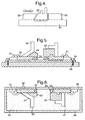
- a fixture (32), figure 2 is bolted onto the rotary table (16).
- the fixture (32) has a base plate (34) onto which a substrate (33) is fastened.
- the substrate (33) is located against blocks (35) mounted on the upper surface of the base plate (34). Some of the blocks (35) may translate relative to the base plate (34) to fasten the substrate (33) in position, figure 4.
- clamps (31), shown in figure 2 are used to fasten the substrate in position.
- the upper surface of the base plate (34), on which the substrate is fastened, is also provided with a series of grooves (36).
- the grooves (36) are in the form of concentric circles, which are interconnected at various radial positions (38).
- the grooves (36) allow argon gas, supplied during the welding process, to circulate freely beneath the substrate (33). The circulation of the argon gas within the grooves (36) prevents stagnant air-rich pockets forming beneath the substrate (33).
- the base plate (34) and the substrate (33) are preheated prior to weld material being deposited. For process uniformity the base plate (34) and the substrate (33) are maintained at a temperature, which ensure steady heat-flow conditions.
- the base plate (34) of the fixture (32) is manufactured from a material, which can be easily maintained at the temperature of the substrate (33).
- the base plate (34) is manufactured from either a heat resistant iron-nickel-chromium alloy or a super alloy.
- the support cores (42) maintain the true shape of the article (40) during the heat treatment process.
- the deposited article (40) can be either coated with foam or wrapped in fabric.
- the foam may be polyurethane or polystyrene and is sprayed onto the article.
- a ceramic cloth, ceramic wool or other lint free material is wrapped around the article (40).
- the article (40), attached to the fixture (32), is then placed into a box (44), figure 6.
- the box (44) is manufactured from mild steel reinforced with a super alloy. It will however be appreciated that the box (44) could be made from different materials provided that it is self-supporting at the temperatures required in the subsequent heat treatment process.
- the box (44) is filled with a granular material (43).
- the granular material (43) is casting sand.
- the sand (43) may be reinforced with either metal or glass spheres.
- the sand (43) is reinforced with glass. The glass forms a vitreous support layer when heated.
- an inert binder is added to the reinforced sand (43) to bind it together to form a cast around the article (40).
- the binder is a gypsum compound, which can withstand exposure to the hot metal temperatures, which are of the order of 780°C. It will however be appreciated by one skilled in the art that any type of binder may be used provided that it can withstand the high temperatures used in the subsequent heat treatment process.
- the article (40) has been sprayed with foam this is removed after the sand (43) has been bound together.
- the foam is removed by baking in a furnace, having a gas extraction system, at a temperature of the order of 300°C.
- the foam vaporises to leave a recess (41) between the article (40) and the sand (43).
- the recess (41) is provided to allow for the thermal expansion of the article (40) during the subsequent heat treatment process.
- the article (40) has been wound in a fabric this can be removed by baking as described above or alternatively it can be removed manually.
- the lid (46) is a circular plate on which stiffening ribs are welded so that it is self-supporting at high temperatures. Holes (45) are provided in the lid (46), which enable it to be lifted but which also prevent gas entrapment during the heat treatment process.
- the lid (46) includes a recess (47) that locates on the article (40). The edges of the recess (47) in the lid (46) are chamfered (48) to allow for easy location and removal. The weight of the lid (46) applies an even pressure on the sand (43), preventing the sand (43) from moving as the article (40) expands during the heat treatment process.
- the box (44) and its contents are then heated to an elevated temperature for a predetermined length of time.
- a titanium deposit would be maintained at a temperature in the range of 500-970°C for a period of approximately two hours.
- the article (40) On completion of the heat treatment the article (40) is removed from the box (44) and is unclamped from the fixture (32).
- the heat treatment process acts to relieve stresses induced in the article (40) during its manufacture so that it does not distort when it is unclamped from the fixture (32).
Landscapes
- Engineering & Computer Science (AREA)
- Physics & Mathematics (AREA)
- Mechanical Engineering (AREA)
- Chemical & Material Sciences (AREA)
- Optics & Photonics (AREA)
- Plasma & Fusion (AREA)
- Materials Engineering (AREA)
- Crystallography & Structural Chemistry (AREA)
- Thermal Sciences (AREA)
- Metallurgy (AREA)
- Organic Chemistry (AREA)
- Health & Medical Sciences (AREA)
- Child & Adolescent Psychology (AREA)
- Arc Welding In General (AREA)
- Heat Treatments In General, Especially Conveying And Cooling (AREA)
- Glanulating (AREA)
- Manufacturing Of Micro-Capsules (AREA)
- Packages (AREA)
- Auxiliary Devices For And Details Of Packaging Control (AREA)
Abstract
Description
Claims (21)
- A method of heat treating an article (40) comprising the steps of forming an article (40) to be heat treated and packing (42) the article (40) to retain its shape, characterised in that the packed article (40) is wrapped in a layer of material, encasing the wrapped article in a granular material (43) and binding the granular material together to form a mould, removing the article (40) from the mould to unwrap it and replacing the unwrapped article (40) in the mould, heating the article (40) and the mould to a temperature which is sufficient to relieve stresses in the article (40) and maintaining the encased article (40) at this temperature for a time period such that the stresses in the article (40) are relieved.
- A method of heat treating an article (40) comprising the steps of forming an article (40) to be heat treated and packing (42) the formed article (40) to retain its shape characterised in that a coating is applied onto the packed article (40), the coated article is then encased in a granular material (43) and the granular material (43) is bound together to form a mould, heating the encased article (40) to a first temperature which is sufficient to remove the coating and then subsequently heating to a second temperature which is sufficient to relieve stresses in the formed article (40), maintaining the encased article (40) at the second temperature for a time period such that the stresses in the article (40) are relieved.
- A method as claimed in claim 2 characterised in that the coating is sprayed onto the article (40).
- A method as claimed in claim 3 characterised in that the coating is sprayed as foam onto the article.
- A method as claimed in any of claims 2-4 characterised in that the coating is polyurethane.
- A method as claimed in any of claims 2-4 characterised in that the coating is polystyrene.
- A method as claimed in claim 1 characterised in that the article (40) is wrapped in a ceramic cloth.
- A method as claimed in any of claims 1-7 characterised in that the article (40) is formed by material deposition.
- A method and apparatus as claimed in claim 8 characterised in that the material is deposited in layers using a welding process.
- A method as claimed in any of claims 1-9 characterised in that ceramic cores (42) are used to pack the article (40).
- A method as claimed in of claims 1-10 characterised in that the granular material (43) is sand.
- A method as claimed in any preceding claim characterised in that the granular material (43) is reinforced.
- A method as claimed in claim 12 characterised in that the granular material (43) is reinforced with glass particles.
- A method as claimed in any of claims 1-13 characterised in that the granular material (43) is bound together by an inert binder.
- A method as claimed in claim 14 characterised in that the binder is gypsum.
- A fixture (32) for holding a substrate (33) onto which an article (40) is to be formed comprising a member (34) having means (35,31) for locating and holding the substrate (33) on a face thereof, at least one recess (36) being provided in said face.
- A fixture (32) as claimed in claim 16 characterised in that the at least one recess (36) is circular.
- A fixture (32) as claimed in claim 16 characterised in that a plurality of circular recesses (36) are provided which are interconnected.
- A fixture (32) as claimed in any of claim 16-18 characterised in that the means for locating the substrate (33) is at least one block (35) mounted on the face.
- A fixture (32) as claimed in any of claims 16-19 characterised in that a plurality of blocks (35) some of which translate relative to the face hold the substrate (33) thereon.
- A fixture (33) as claimed in any of claims 16-18 in which the means for holding the substrate (33) are clamps (31).
Applications Claiming Priority (2)
| Application Number | Priority Date | Filing Date | Title |
|---|---|---|---|
| GB0329268 | 2003-12-17 | ||
| GBGB0329268.7A GB0329268D0 (en) | 2003-12-17 | 2003-12-17 | Method and apparatus for heat-treating an article and a fixture for use in the same |
Publications (3)
| Publication Number | Publication Date |
|---|---|
| EP1543908A2 true EP1543908A2 (en) | 2005-06-22 |
| EP1543908A3 EP1543908A3 (en) | 2005-10-12 |
| EP1543908B1 EP1543908B1 (en) | 2007-11-07 |
Family
ID=30471250
Family Applications (1)
| Application Number | Title | Priority Date | Filing Date |
|---|---|---|---|
| EP04257375A Expired - Lifetime EP1543908B1 (en) | 2003-12-17 | 2004-11-27 | Method for heat-treating a packed article encased in a granular material |
Country Status (6)
| Country | Link |
|---|---|
| US (2) | US7344608B2 (en) |
| EP (1) | EP1543908B1 (en) |
| AT (1) | ATE377476T1 (en) |
| DE (1) | DE602004009883T2 (en) |
| ES (1) | ES2293173T3 (en) |
| GB (1) | GB0329268D0 (en) |
Cited By (3)
| Publication number | Priority date | Publication date | Assignee | Title |
|---|---|---|---|---|
| GB2531704A (en) * | 2014-10-17 | 2016-05-04 | Airbusgroup Ltd | Method of additive maufacturing and heat treatment |
| GB2546165A (en) * | 2015-12-11 | 2017-07-12 | Ford Global Tech Llc | Vehicle component fabrication |
| US12042867B2 (en) | 2019-03-25 | 2024-07-23 | Airbus Operations Limited | Fixture for additive manufacturing and heat treatment |
Families Citing this family (7)
| Publication number | Priority date | Publication date | Assignee | Title |
|---|---|---|---|---|
| GB0329268D0 (en) * | 2003-12-17 | 2004-01-21 | Rolls Royce Plc | Method and apparatus for heat-treating an article and a fixture for use in the same |
| JP2007111716A (en) * | 2005-10-19 | 2007-05-10 | Showa Denko Kk | Clamping device, joining device and joining method |
| US20090277877A1 (en) * | 2008-05-08 | 2009-11-12 | Daniels Craig A | Apparatus and method for welding objects |
| RU2518813C1 (en) * | 2012-12-28 | 2014-06-10 | Федеральное государственное автономное образовательное учреждение высшего профессионального образования "МИСиС" | Out-of-furnace processing of welded articles |
| US20200114581A1 (en) * | 2018-10-16 | 2020-04-16 | Krzysztof Wilk | Methods for manufacturing spatial objects |
| CN116748657B (en) * | 2023-07-28 | 2025-10-14 | 沈阳飞机工业(集团)有限公司 | Electron beam welding method for special-shaped double T-shaped net size components |
| CN116900596B (en) * | 2023-07-31 | 2024-04-09 | 安徽正特机电科技有限公司 | Be used for anchor clamps structure of staple bolt welded quick centre gripping |
Family Cites Families (25)
| Publication number | Priority date | Publication date | Assignee | Title |
|---|---|---|---|---|
| GB709632A (en) | 1950-11-23 | 1954-06-02 | Mond Nickel Co Ltd | Improvements relating to the heat-treatment of metals and alloys |
| US2907084A (en) * | 1956-03-27 | 1959-10-06 | Aluminum Co Of America | Hollow cores for making castings |
| GB856765A (en) | 1958-07-11 | 1960-12-21 | Johnson Matthey Co Ltd | Improvements in and relating to the heat-treatment of metal objects |
| GB898232A (en) * | 1958-12-01 | 1962-06-06 | Foseco Int | Improvements in the heat treating of welds |
| US2993980A (en) | 1959-07-30 | 1961-07-25 | Westinghouse Electric Corp | Method for making tubular structure |
| GB931259A (en) | 1961-05-10 | 1963-07-17 | John Charles Wright | Annealing of malleable iron |
| GB1045692A (en) * | 1964-01-07 | 1966-10-19 | Davy & United Eng Co Ltd | Heat treatment method |
| WO1979000156A1 (en) * | 1977-09-22 | 1979-04-05 | R Bergman | Centering pin for air float machine tool tables |
| DE3315246C2 (en) * | 1983-04-27 | 1986-05-07 | Messerschmitt-Bölkow-Blohm GmbH, 8000 München | Component in sandwich construction |
| JPS62174327A (en) | 1986-01-27 | 1987-07-31 | Fuji Kogyosho:Kk | Method for hardening outside surface of cylindrical body |
| US5114501A (en) * | 1989-11-09 | 1992-05-19 | Allegheny Ludlum Corporation | Method employing skin-pass rolling to enhance the quality of phosphorous-striped silicon steel |
| CA2031758C (en) | 1989-12-15 | 1995-10-17 | Roy D. Gravener | Pressurized powder support for treating processes |
| DE4037544A1 (en) * | 1990-11-26 | 1992-05-27 | Bernhard Ringler | DEVICE FOR SUCTIONING PROCESSING RESIDUES RESULTING ON A MACHINING MACHINE IN THE AREA OF A WORKPIECE |
| ES2120414T3 (en) * | 1991-01-21 | 1998-11-01 | Sulzer Hydro Ag | METHOD OF MANUFACTURE OF METAL PARTS BY A WELDING APPARATUS, AND APPARATUS FOR ITS REALIZATION. |
| US5306361A (en) * | 1992-10-02 | 1994-04-26 | Besch Gordon O | Method for improving service life of rail welds by aluminothermic heat treatment |
| IT1268004B1 (en) * | 1994-02-02 | 1997-02-20 | Giuseppe Lambertini | DEVICE FOR LOCKING A PIECE ON A SUPPORT SURFACE, SUCH AS AN OPERATING MACHINE TABLE. |
| US5833225A (en) * | 1995-11-13 | 1998-11-10 | Weber; Gene | Gripping device |
| US5711826A (en) * | 1996-04-12 | 1998-01-27 | Crs Holdings, Inc. | Functionally gradient cladding for nuclear fuel rods |
| JP3663479B2 (en) * | 1998-10-07 | 2005-06-22 | オークマ株式会社 | Workpiece positioning jig for machine tools |
| GB9826728D0 (en) * | 1998-12-04 | 1999-01-27 | Rolls Royce Plc | Method and apparatus for building up a workpiece by deposit welding |
| JP2000202729A (en) * | 1999-01-18 | 2000-07-25 | Ntn Corp | Linear drive for vacuum |
| US6672367B2 (en) * | 1999-07-29 | 2004-01-06 | Consolidated Engineering Company, Inc. | Methods and apparatus for heat treatment and sand removal for castings |
| GB0107562D0 (en) * | 2001-03-27 | 2001-05-16 | Rolls Royce Plc | Method for forming a body |
| US6506048B1 (en) * | 2001-11-01 | 2003-01-14 | Procedyne Corp. | Apparatus and method for transferring heat treated parts |
| GB0329268D0 (en) * | 2003-12-17 | 2004-01-21 | Rolls Royce Plc | Method and apparatus for heat-treating an article and a fixture for use in the same |
-
2003
- 2003-12-17 GB GBGB0329268.7A patent/GB0329268D0/en not_active Ceased
-
2004
- 2004-11-27 AT AT04257375T patent/ATE377476T1/en active
- 2004-11-27 EP EP04257375A patent/EP1543908B1/en not_active Expired - Lifetime
- 2004-11-27 DE DE602004009883T patent/DE602004009883T2/en not_active Expired - Lifetime
- 2004-11-27 ES ES04257375T patent/ES2293173T3/en not_active Expired - Lifetime
- 2004-12-14 US US11/010,479 patent/US7344608B2/en not_active Expired - Fee Related
-
2007
- 2007-10-03 US US11/905,695 patent/US7718015B2/en not_active Expired - Fee Related
Cited By (6)
| Publication number | Priority date | Publication date | Assignee | Title |
|---|---|---|---|---|
| GB2531704A (en) * | 2014-10-17 | 2016-05-04 | Airbusgroup Ltd | Method of additive maufacturing and heat treatment |
| US10676800B2 (en) | 2014-10-17 | 2020-06-09 | Airbus Operations Limited | Method of additive manufacturing and heat treatment |
| GB2546165A (en) * | 2015-12-11 | 2017-07-12 | Ford Global Tech Llc | Vehicle component fabrication |
| US10307781B2 (en) | 2015-12-11 | 2019-06-04 | Ford Global Technologies, Llc | Vehicle component fabrication |
| GB2546165B (en) * | 2015-12-11 | 2022-12-21 | Ford Global Tech Llc | Vehicle component fabrication |
| US12042867B2 (en) | 2019-03-25 | 2024-07-23 | Airbus Operations Limited | Fixture for additive manufacturing and heat treatment |
Also Published As
| Publication number | Publication date |
|---|---|
| DE602004009883T2 (en) | 2008-02-28 |
| ATE377476T1 (en) | 2007-11-15 |
| US7718015B2 (en) | 2010-05-18 |
| EP1543908B1 (en) | 2007-11-07 |
| GB0329268D0 (en) | 2004-01-21 |
| EP1543908A3 (en) | 2005-10-12 |
| US20050133482A1 (en) | 2005-06-23 |
| ES2293173T3 (en) | 2008-03-16 |
| US20080029927A1 (en) | 2008-02-07 |
| DE602004009883D1 (en) | 2007-12-20 |
| US7344608B2 (en) | 2008-03-18 |
Similar Documents
| Publication | Publication Date | Title |
|---|---|---|
| US7718015B2 (en) | Method and apparatus for heat-treating an article and a fixture for use in the same | |
| US7034262B2 (en) | Apparatus and methods for repairing tenons on turbine buckets | |
| JP7303034B2 (en) | Fusing foil additive manufacturing system and method | |
| EP0740977B1 (en) | Containerless method of producing crack free metallic articles | |
| US20210154732A1 (en) | Distortion mitigation in directed energy deposition | |
| KR20150063312A (en) | A composite welding wire and method of manufacturing | |
| US12048965B2 (en) | Distortion mitigation in directed energy deposition | |
| JP2020531287A (en) | Laser metal deposition of high gamma prime superalloy with cooling effect | |
| WO2020023008A1 (en) | Method to enhance geometric resolution in arc and high deposition additive manufacturing | |
| CN1120067C (en) | Bimetallic plate | |
| EP1798316B1 (en) | Repair method of crystalline structures by epitaxy | |
| EP3677363B1 (en) | Support frame | |
| EP1245321B1 (en) | Apparatus and method for forming a body by free form welding | |
| JP7130383B2 (en) | Welding methods and welded articles | |
| GB2438841A (en) | Fixture having heating means | |
| KR20240007941A (en) | Directed energy deposition methods to create mounting systems, pin support systems, and metal workpieces to mitigate distortion. | |
| JP6924013B2 (en) | Filled metal for superalloys and manufacturing method | |
| KR101449454B1 (en) | Method and apparatus of pipe | |
| JPS62173083A (en) | Build-up welding method for outside surface of cylindrical body | |
| JPH0732165A (en) | Method for depositing hardening material on base metal | |
| JPH01252762A (en) | Method for coating inner surface of metallic cylinder | |
| CS269616B1 (en) | A method of applying a protective layer to the inner surface of hollow bodies |
Legal Events
| Date | Code | Title | Description |
|---|---|---|---|
| REG | Reference to a national code |
Ref country code: SE Ref legal event code: TRGR |
|
| PUAI | Public reference made under article 153(3) epc to a published international application that has entered the european phase |
Free format text: ORIGINAL CODE: 0009012 |
|
| AK | Designated contracting states |
Kind code of ref document: A2 Designated state(s): AT BE BG CH CY CZ DE DK EE ES FI FR GB GR HU IE IS IT LI LU MC NL PL PT RO SE SI SK TR |
|
| AX | Request for extension of the european patent |
Extension state: AL HR LT LV MK YU |
|
| 17P | Request for examination filed |
Effective date: 20050609 |
|
| PUAL | Search report despatched |
Free format text: ORIGINAL CODE: 0009013 |
|
| RIC1 | Information provided on ipc code assigned before grant |
Ipc: 7B 23K 37/04 B Ipc: 7B 23K 10/02 B Ipc: 7B 23Q 1/03 B Ipc: 7B 23Q 3/10 B Ipc: 7C 21D 1/44 B Ipc: 7B 23K 9/04 A Ipc: 7C 21D 9/50 B Ipc: 7B 23K 15/00 B Ipc: 7B 23K 26/34 B |
|
| AK | Designated contracting states |
Kind code of ref document: A3 Designated state(s): AT BE BG CH CY CZ DE DK EE ES FI FR GB GR HU IE IS IT LI LU MC NL PL PT RO SE SI SK TR |
|
| AX | Request for extension of the european patent |
Extension state: AL HR LT LV MK YU |
|
| AKX | Designation fees paid |
Designated state(s): AT BE BG CH CY CZ DE DK EE ES FI FR GB GR HU IE IS IT LI LU MC NL PL PT RO SE SI SK TR |
|
| RTI1 | Title (correction) |
Free format text: METHOD FOR HEAT-TREATING A PACKED ARTICLE ENCASED IN A GRANULAR MATERIAL |
|
| GRAP | Despatch of communication of intention to grant a patent |
Free format text: ORIGINAL CODE: EPIDOSNIGR1 |
|
| GRAS | Grant fee paid |
Free format text: ORIGINAL CODE: EPIDOSNIGR3 |
|
| GRAA | (expected) grant |
Free format text: ORIGINAL CODE: 0009210 |
|
| AK | Designated contracting states |
Kind code of ref document: B1 Designated state(s): AT BE BG CH CY CZ DE DK EE ES FI FR GB GR HU IE IS IT LI LU MC NL PL PT RO SE SI SK TR |
|
| REG | Reference to a national code |
Ref country code: GB Ref legal event code: FG4D |
|
| REG | Reference to a national code |
Ref country code: IE Ref legal event code: FG4D |
|
| REG | Reference to a national code |
Ref country code: CH Ref legal event code: EP |
|
| REF | Corresponds to: |
Ref document number: 602004009883 Country of ref document: DE Date of ref document: 20071220 Kind code of ref document: P |
|
| REG | Reference to a national code |
Ref country code: CH Ref legal event code: NV Representative=s name: KIRKER & CIE S.A. |
|
| REG | Reference to a national code |
Ref country code: ES Ref legal event code: FG2A Ref document number: 2293173 Country of ref document: ES Kind code of ref document: T3 |
|
| PG25 | Lapsed in a contracting state [announced via postgrant information from national office to epo] |
Ref country code: SI Free format text: LAPSE BECAUSE OF FAILURE TO SUBMIT A TRANSLATION OF THE DESCRIPTION OR TO PAY THE FEE WITHIN THE PRESCRIBED TIME-LIMIT Effective date: 20071107 Ref country code: PL Free format text: LAPSE BECAUSE OF FAILURE TO SUBMIT A TRANSLATION OF THE DESCRIPTION OR TO PAY THE FEE WITHIN THE PRESCRIBED TIME-LIMIT Effective date: 20071107 Ref country code: BG Free format text: LAPSE BECAUSE OF FAILURE TO SUBMIT A TRANSLATION OF THE DESCRIPTION OR TO PAY THE FEE WITHIN THE PRESCRIBED TIME-LIMIT Effective date: 20080207 Ref country code: IS Free format text: LAPSE BECAUSE OF FAILURE TO SUBMIT A TRANSLATION OF THE DESCRIPTION OR TO PAY THE FEE WITHIN THE PRESCRIBED TIME-LIMIT Effective date: 20080307 |
|
| PG25 | Lapsed in a contracting state [announced via postgrant information from national office to epo] |
Ref country code: MC Free format text: LAPSE BECAUSE OF NON-PAYMENT OF DUE FEES Effective date: 20071130 |
|
| ET | Fr: translation filed | ||
| PG25 | Lapsed in a contracting state [announced via postgrant information from national office to epo] |
Ref country code: DK Free format text: LAPSE BECAUSE OF FAILURE TO SUBMIT A TRANSLATION OF THE DESCRIPTION OR TO PAY THE FEE WITHIN THE PRESCRIBED TIME-LIMIT Effective date: 20071107 Ref country code: CZ Free format text: LAPSE BECAUSE OF FAILURE TO SUBMIT A TRANSLATION OF THE DESCRIPTION OR TO PAY THE FEE WITHIN THE PRESCRIBED TIME-LIMIT Effective date: 20071107 |
|
| PG25 | Lapsed in a contracting state [announced via postgrant information from national office to epo] |
Ref country code: SK Free format text: LAPSE BECAUSE OF FAILURE TO SUBMIT A TRANSLATION OF THE DESCRIPTION OR TO PAY THE FEE WITHIN THE PRESCRIBED TIME-LIMIT Effective date: 20071107 Ref country code: RO Free format text: LAPSE BECAUSE OF FAILURE TO SUBMIT A TRANSLATION OF THE DESCRIPTION OR TO PAY THE FEE WITHIN THE PRESCRIBED TIME-LIMIT Effective date: 20071107 |
|
| PLBE | No opposition filed within time limit |
Free format text: ORIGINAL CODE: 0009261 |
|
| STAA | Information on the status of an ep patent application or granted ep patent |
Free format text: STATUS: NO OPPOSITION FILED WITHIN TIME LIMIT |
|
| PG25 | Lapsed in a contracting state [announced via postgrant information from national office to epo] |
Ref country code: PT Free format text: LAPSE BECAUSE OF FAILURE TO SUBMIT A TRANSLATION OF THE DESCRIPTION OR TO PAY THE FEE WITHIN THE PRESCRIBED TIME-LIMIT Effective date: 20080407 |
|
| 26N | No opposition filed |
Effective date: 20080808 |
|
| PG25 | Lapsed in a contracting state [announced via postgrant information from national office to epo] |
Ref country code: IE Free format text: LAPSE BECAUSE OF NON-PAYMENT OF DUE FEES Effective date: 20071127 |
|
| PG25 | Lapsed in a contracting state [announced via postgrant information from national office to epo] |
Ref country code: GR Free format text: LAPSE BECAUSE OF FAILURE TO SUBMIT A TRANSLATION OF THE DESCRIPTION OR TO PAY THE FEE WITHIN THE PRESCRIBED TIME-LIMIT Effective date: 20080208 Ref country code: EE Free format text: LAPSE BECAUSE OF FAILURE TO SUBMIT A TRANSLATION OF THE DESCRIPTION OR TO PAY THE FEE WITHIN THE PRESCRIBED TIME-LIMIT Effective date: 20071107 |
|
| PG25 | Lapsed in a contracting state [announced via postgrant information from national office to epo] |
Ref country code: FI Free format text: LAPSE BECAUSE OF FAILURE TO SUBMIT A TRANSLATION OF THE DESCRIPTION OR TO PAY THE FEE WITHIN THE PRESCRIBED TIME-LIMIT Effective date: 20071107 |
|
| PG25 | Lapsed in a contracting state [announced via postgrant information from national office to epo] |
Ref country code: CY Free format text: LAPSE BECAUSE OF FAILURE TO SUBMIT A TRANSLATION OF THE DESCRIPTION OR TO PAY THE FEE WITHIN THE PRESCRIBED TIME-LIMIT Effective date: 20071107 |
|
| PG25 | Lapsed in a contracting state [announced via postgrant information from national office to epo] |
Ref country code: LU Free format text: LAPSE BECAUSE OF NON-PAYMENT OF DUE FEES Effective date: 20071127 |
|
| PG25 | Lapsed in a contracting state [announced via postgrant information from national office to epo] |
Ref country code: HU Free format text: LAPSE BECAUSE OF FAILURE TO SUBMIT A TRANSLATION OF THE DESCRIPTION OR TO PAY THE FEE WITHIN THE PRESCRIBED TIME-LIMIT Effective date: 20080508 Ref country code: TR Free format text: LAPSE BECAUSE OF FAILURE TO SUBMIT A TRANSLATION OF THE DESCRIPTION OR TO PAY THE FEE WITHIN THE PRESCRIBED TIME-LIMIT Effective date: 20071107 |
|
| PGFP | Annual fee paid to national office [announced via postgrant information from national office to epo] |
Ref country code: GB Payment date: 20141127 Year of fee payment: 11 Ref country code: ES Payment date: 20141126 Year of fee payment: 11 Ref country code: CH Payment date: 20141127 Year of fee payment: 11 Ref country code: SE Payment date: 20141128 Year of fee payment: 11 |
|
| PGFP | Annual fee paid to national office [announced via postgrant information from national office to epo] |
Ref country code: NL Payment date: 20141126 Year of fee payment: 11 Ref country code: AT Payment date: 20141103 Year of fee payment: 11 |
|
| PGFP | Annual fee paid to national office [announced via postgrant information from national office to epo] |
Ref country code: IT Payment date: 20141126 Year of fee payment: 11 |
|
| PGFP | Annual fee paid to national office [announced via postgrant information from national office to epo] |
Ref country code: BE Payment date: 20141128 Year of fee payment: 11 |
|
| REG | Reference to a national code |
Ref country code: FR Ref legal event code: PLFP Year of fee payment: 12 |
|
| REG | Reference to a national code |
Ref country code: CH Ref legal event code: PL |
|
| REG | Reference to a national code |
Ref country code: AT Ref legal event code: MM01 Ref document number: 377476 Country of ref document: AT Kind code of ref document: T Effective date: 20151127 |
|
| GBPC | Gb: european patent ceased through non-payment of renewal fee |
Effective date: 20151127 |
|
| PG25 | Lapsed in a contracting state [announced via postgrant information from national office to epo] |
Ref country code: IT Free format text: LAPSE BECAUSE OF NON-PAYMENT OF DUE FEES Effective date: 20151127 Ref country code: CH Free format text: LAPSE BECAUSE OF NON-PAYMENT OF DUE FEES Effective date: 20151130 Ref country code: LI Free format text: LAPSE BECAUSE OF NON-PAYMENT OF DUE FEES Effective date: 20151130 |
|
| REG | Reference to a national code |
Ref country code: NL Ref legal event code: MM Effective date: 20151201 |
|
| PG25 | Lapsed in a contracting state [announced via postgrant information from national office to epo] |
Ref country code: SE Free format text: LAPSE BECAUSE OF NON-PAYMENT OF DUE FEES Effective date: 20151128 Ref country code: AT Free format text: LAPSE BECAUSE OF NON-PAYMENT OF DUE FEES Effective date: 20151127 |
|
| PG25 | Lapsed in a contracting state [announced via postgrant information from national office to epo] |
Ref country code: NL Free format text: LAPSE BECAUSE OF NON-PAYMENT OF DUE FEES Effective date: 20151201 |
|
| PG25 | Lapsed in a contracting state [announced via postgrant information from national office to epo] |
Ref country code: GB Free format text: LAPSE BECAUSE OF NON-PAYMENT OF DUE FEES Effective date: 20151127 |
|
| REG | Reference to a national code |
Ref country code: FR Ref legal event code: PLFP Year of fee payment: 13 |
|
| REG | Reference to a national code |
Ref country code: ES Ref legal event code: FD2A Effective date: 20161228 |
|
| PG25 | Lapsed in a contracting state [announced via postgrant information from national office to epo] |
Ref country code: ES Free format text: LAPSE BECAUSE OF NON-PAYMENT OF DUE FEES Effective date: 20151128 |
|
| PG25 | Lapsed in a contracting state [announced via postgrant information from national office to epo] |
Ref country code: BE Free format text: LAPSE BECAUSE OF NON-PAYMENT OF DUE FEES Effective date: 20151130 |
|
| REG | Reference to a national code |
Ref country code: FR Ref legal event code: PLFP Year of fee payment: 14 |
|
| PGFP | Annual fee paid to national office [announced via postgrant information from national office to epo] |
Ref country code: DE Payment date: 20181128 Year of fee payment: 15 |
|
| PGFP | Annual fee paid to national office [announced via postgrant information from national office to epo] |
Ref country code: FR Payment date: 20181127 Year of fee payment: 15 |
|
| REG | Reference to a national code |
Ref country code: DE Ref legal event code: R119 Ref document number: 602004009883 Country of ref document: DE |
|
| PG25 | Lapsed in a contracting state [announced via postgrant information from national office to epo] |
Ref country code: DE Free format text: LAPSE BECAUSE OF NON-PAYMENT OF DUE FEES Effective date: 20200603 Ref country code: FR Free format text: LAPSE BECAUSE OF NON-PAYMENT OF DUE FEES Effective date: 20191130 |