EP1542351A2 - Motor driving apparatus for use in a dishwasher - Google Patents
Motor driving apparatus for use in a dishwasher Download PDFInfo
- Publication number
- EP1542351A2 EP1542351A2 EP04028485A EP04028485A EP1542351A2 EP 1542351 A2 EP1542351 A2 EP 1542351A2 EP 04028485 A EP04028485 A EP 04028485A EP 04028485 A EP04028485 A EP 04028485A EP 1542351 A2 EP1542351 A2 EP 1542351A2
- Authority
- EP
- European Patent Office
- Prior art keywords
- motor
- current
- inverter circuit
- phase
- output
- Prior art date
- Legal status (The legal status is an assumption and is not a legal conclusion. Google has not performed a legal analysis and makes no representation as to the accuracy of the status listed.)
- Withdrawn
Links
- 230000001360 synchronised effect Effects 0.000 claims description 9
- XLYOFNOQVPJJNP-UHFFFAOYSA-N water Substances O XLYOFNOQVPJJNP-UHFFFAOYSA-N 0.000 description 21
- 238000000034 method Methods 0.000 description 15
- 230000001965 increasing effect Effects 0.000 description 14
- 238000001514 detection method Methods 0.000 description 11
- 230000008569 process Effects 0.000 description 11
- 230000009466 transformation Effects 0.000 description 11
- 238000010586 diagram Methods 0.000 description 10
- 230000008859 change Effects 0.000 description 8
- 230000001131 transforming effect Effects 0.000 description 7
- 238000005406 washing Methods 0.000 description 7
- 230000001276 controlling effect Effects 0.000 description 6
- 239000003990 capacitor Substances 0.000 description 5
- 230000009467 reduction Effects 0.000 description 5
- 238000001035 drying Methods 0.000 description 4
- 239000000969 carrier Substances 0.000 description 3
- 238000006243 chemical reaction Methods 0.000 description 3
- 238000004140 cleaning Methods 0.000 description 3
- 230000003247 decreasing effect Effects 0.000 description 3
- 238000002347 injection Methods 0.000 description 3
- 239000007924 injection Substances 0.000 description 3
- 238000009434 installation Methods 0.000 description 3
- 230000007246 mechanism Effects 0.000 description 3
- 238000003860 storage Methods 0.000 description 3
- 230000000694 effects Effects 0.000 description 2
- 230000002708 enhancing effect Effects 0.000 description 2
- 230000001105 regulatory effect Effects 0.000 description 2
- 238000009877 rendering Methods 0.000 description 2
- 230000004043 responsiveness Effects 0.000 description 2
- XEEYBQQBJWHFJM-UHFFFAOYSA-N Iron Chemical group [Fe] XEEYBQQBJWHFJM-UHFFFAOYSA-N 0.000 description 1
- 230000005856 abnormality Effects 0.000 description 1
- 230000008878 coupling Effects 0.000 description 1
- 238000010168 coupling process Methods 0.000 description 1
- 238000005859 coupling reaction Methods 0.000 description 1
- 230000002542 deteriorative effect Effects 0.000 description 1
- 230000007274 generation of a signal involved in cell-cell signaling Effects 0.000 description 1
- 238000004519 manufacturing process Methods 0.000 description 1
- 230000004048 modification Effects 0.000 description 1
- 238000012986 modification Methods 0.000 description 1
- 230000007935 neutral effect Effects 0.000 description 1
- 239000004065 semiconductor Substances 0.000 description 1
- 239000008399 tap water Substances 0.000 description 1
- 235000020679 tap water Nutrition 0.000 description 1
Images


Classifications
-
- H—ELECTRICITY
- H02—GENERATION; CONVERSION OR DISTRIBUTION OF ELECTRIC POWER
- H02P—CONTROL OR REGULATION OF ELECTRIC MOTORS, ELECTRIC GENERATORS OR DYNAMO-ELECTRIC CONVERTERS; CONTROLLING TRANSFORMERS, REACTORS OR CHOKE COILS
- H02P7/00—Arrangements for regulating or controlling the speed or torque of electric DC motors
- H02P7/06—Arrangements for regulating or controlling the speed or torque of electric DC motors for regulating or controlling an individual dc dynamo-electric motor by varying field or armature current
- H02P7/18—Arrangements for regulating or controlling the speed or torque of electric DC motors for regulating or controlling an individual dc dynamo-electric motor by varying field or armature current by master control with auxiliary power
- H02P7/34—Arrangements for regulating or controlling the speed or torque of electric DC motors for regulating or controlling an individual dc dynamo-electric motor by varying field or armature current by master control with auxiliary power using Ward-Leonard arrangements
-
- A—HUMAN NECESSITIES
- A47—FURNITURE; DOMESTIC ARTICLES OR APPLIANCES; COFFEE MILLS; SPICE MILLS; SUCTION CLEANERS IN GENERAL
- A47L—DOMESTIC WASHING OR CLEANING; SUCTION CLEANERS IN GENERAL
- A47L15/00—Washing or rinsing machines for crockery or tableware
- A47L15/42—Details
- A47L15/4214—Water supply, recirculation or discharge arrangements; Devices therefor
- A47L15/4225—Arrangements or adaption of recirculation or discharge pumps
-
- A—HUMAN NECESSITIES
- A47—FURNITURE; DOMESTIC ARTICLES OR APPLIANCES; COFFEE MILLS; SPICE MILLS; SUCTION CLEANERS IN GENERAL
- A47L—DOMESTIC WASHING OR CLEANING; SUCTION CLEANERS IN GENERAL
- A47L15/00—Washing or rinsing machines for crockery or tableware
- A47L15/42—Details
-
- A—HUMAN NECESSITIES
- A47—FURNITURE; DOMESTIC ARTICLES OR APPLIANCES; COFFEE MILLS; SPICE MILLS; SUCTION CLEANERS IN GENERAL
- A47L—DOMESTIC WASHING OR CLEANING; SUCTION CLEANERS IN GENERAL
- A47L15/00—Washing or rinsing machines for crockery or tableware
- A47L15/42—Details
- A47L15/46—Devices for the automatic control of the different phases of cleaning ; Controlling devices
-
- H—ELECTRICITY
- H02—GENERATION; CONVERSION OR DISTRIBUTION OF ELECTRIC POWER
- H02P—CONTROL OR REGULATION OF ELECTRIC MOTORS, ELECTRIC GENERATORS OR DYNAMO-ELECTRIC CONVERTERS; CONTROLLING TRANSFORMERS, REACTORS OR CHOKE COILS
- H02P6/00—Arrangements for controlling synchronous motors or other dynamo-electric motors using electronic commutation dependent on the rotor position; Electronic commutators therefor
- H02P6/08—Arrangements for controlling the speed or torque of a single motor
-
- H—ELECTRICITY
- H02—GENERATION; CONVERSION OR DISTRIBUTION OF ELECTRIC POWER
- H02P—CONTROL OR REGULATION OF ELECTRIC MOTORS, ELECTRIC GENERATORS OR DYNAMO-ELECTRIC CONVERTERS; CONTROLLING TRANSFORMERS, REACTORS OR CHOKE COILS
- H02P6/00—Arrangements for controlling synchronous motors or other dynamo-electric motors using electronic commutation dependent on the rotor position; Electronic commutators therefor
- H02P6/20—Arrangements for starting
- H02P6/21—Open loop start
-
- A—HUMAN NECESSITIES
- A47—FURNITURE; DOMESTIC ARTICLES OR APPLIANCES; COFFEE MILLS; SPICE MILLS; SUCTION CLEANERS IN GENERAL
- A47L—DOMESTIC WASHING OR CLEANING; SUCTION CLEANERS IN GENERAL
- A47L15/00—Washing or rinsing machines for crockery or tableware
- A47L15/0018—Controlling processes, i.e. processes to control the operation of the machine characterised by the purpose or target of the control
- A47L15/0052—Noise reduction
Definitions
- the present invention relates to a dishwasher for cleaning household dishware.
- an object of the present invention to provide a pump motor with a reduced noise by sensorlessly driving a motor with a sine wave, wherein a position sensor is removed to make the motor thinner, smaller and cheaper, thereby enhancing reliability thereof.
- an apparatus for driving a motor of a dishwasher including: an AC power source; a rectification circuit for converting an AC power from the AC power source to a DC power; an inverter circuit for converting the DC power from the rectification circuit to an AC power; a motor driven by the inverter circuit to drive a wash pump and/or a drain pump; a current detector for detecting an output current of the inverter circuit; and a controller for performing a PWM (pulse width modulation) control of the inverter circuit based on an output signal of the current detector to thereby control the motor to rotate at a set rotation speed, wherein a phase difference between an output voltage and the output current of the inverter circuit or a reactive current may be controlled to have a predetermined value.
- PWM pulse width modulation
- the inverter circuit can be configured as a three phase full-bridge inverter circuit including six transistors and six diodes
- the current detector can include shunt resistors respectively connected to negative potential terminals of lower arm transistors of the three phase full-bridge inverter circuit, wherein the output current of the inverter circuit can be detected by detecting a current flowing through the shunt resistors. Therefore, since it becomes easier to detect a DC component and to configure the current detector by using the shunt resistors of low price, the current detector can be designed to have a small size and a low-price sensorless motor driving apparatus can be obtained.
- the motor may be a position-sensorless brushless DC motor having a planar shape. Therefore, the motor can be reduced in its size and can be configured to have a planar shape because it does not incorporate a position sensor therein. As a result, installation area for the motor in a bottom portion of a washer tub can be reduced, which in turn increases the volume of the portion in the washer tub for accommodating dishware. Thus, a large-capacity for dishwasher can be realized.
- the output current of the inverter circuit and an induced voltage of the motor may be controlled to have a substantially identical phase by way of controlling the phase between the output voltage and the output current of the inverter circuit or the reactive current to have the predetermined value.
- the motor current can be reduced, thereby enabling operation of maximum efficiency.
- the size and thickness of the motor can be reduced.
- the installation area for the motor can be further reduced such that the volume of the portion in the washer tub for accommodating dishware can be increased, while realizing a large-capacity compact dishwasher at a low price.
- the output current of the inverter circuit may be controlled to lead the induced voltage of the motor by way of controlling the phase difference between the output voltage and the output current of the inverter circuit or the reactive current to have the predetermined value.
- the phase difference between the output voltage and the output current of the inverter circuit or the reactive current may be controlled to have the predetermined value by way of detecting the output current of the inverter circuit by means of the current detector in synchronous with a switching period for the PWM control of the inverter circuit and comparing a value of the output current detected by the current detector with a value of an output current that is calculated and set in synchronous with the switching period.
- detection of the phase of the motor current, the reactive current or an absolute value of current becomes feasible by using a carrier frequency higher than a motor driving frequency, and it becomes possible to cope with the change in the load of the motor by reducing a time period required to respond to a motor control.
- stable operation can be achieved even when there occurs a sudden change of the load on the motor, such as an inflow of air.
- a wash pump operation or a drain pump operation may be enabled by allowing the motor to make forward or backward rotations, and an inflow of air in the wash pump or the drain pump can be detected if the output current of the inverter circuit falls below a preset value while driving the wash pump or the drain pump by controlling the motor to rotate at a set rotation speed.
- the rotation speed of the motor may be reduced or the quantity of wash water may be increased.
- the operating time can be reduced, thereby lowering the generation of noise.
- FIG. 1 there is provided a block diagram of a motor driving apparatus incorporated in a dishwasher in accordance with a first preferred embodiment of the present invention.
- an AC power supplied from AC power source 1 is converted to a DC power by rectification circuit 2, and the DC power is converted to a three phase AC power by inverter circuit 3 in order to drive motor 4.
- rectification circuit 2 by connecting capacitors 21a and 21b between DC output terminals of full-wave rectification circuit 20 in series and coupling a connection node between two capacitors 21a and 21b to one of AC power input terminals of full-wave rectification circuit 20, rectification circuit 2 is configured as a DC voltage doubler circuit which serves to increase voltage applied to the inverter circuit 3.
- current detector 5 which is connected to a negative voltage side of inverter circuit 3, detects respective currents flowing through three phase lower arms of inverter circuit 3 to thereby detect output currents of inverter circuit 3, i.e., respective three phase currents of motor 4.
- Controller 6 calculates the output current of inverter circuit 3 from an output signal of current detector 5, and rotates motor 4 by applying a power of a predetermined frequency and a preset voltage to motor 4 corresponding to a set rotation speed of motor 4. At this time, by controlling a phase of an output current with respect to an output voltage or a reactive current according to a load on motor 4, motor 4 can be made to rotate at a set synchronous speed.
- Fig. 2 is a detailed circuit diagram of inverter circuit 3, which is configured as a three phase full-bridge inverter circuit including six transistors and six diodes.
- U phase arm 30A which is one of three phase arms, will be described.
- An upper parallel connection unit including upper arm transistor 31a1 and anti-parallel diode 32a1 that are connected in parallel to each other and a lower parallel connection unit including lower arm transistor 31a2 and anti-parallel diode 32a2 that are connected in parallel to each other are coupled to each other in series, wherein each of upper and lower arm transistor 31a1 and 31a2 is made up of an insulated gate bipolar transistor (hereinafter, refereed to as an IGBT).
- IGBT insulated gate bipolar transistor
- a collector terminal of upper arm transistor 31a1 is connected to a positive potential terminal Lp of a DC power source while an emitter terminal thereof is coupled to output terminal U of inverter circuit 3. Further, an emitter terminal of lower arm transistor 31a2 is connected to negative potential terminal Ln of the DC power source via shunt resistor 50a which forms current detector 5.
- Upper arm transistor 31a1 is driven by upper arm gate driving circuit 33a1 based on upper arm driving signal Up while lower arm transistor 31a2 is on-off operated by lower arm gate driving circuit 33a2 in accordance with lower arm driving signal Un.
- Upper arm gate driving circuit 33a1 which incorporates therein an RS flip-flop circuit that is set and rest by a differential signal, on-operates upper arm transistor 31a1 when upper arm driving signal Up rises, whereas it off-operates upper arm transistor 31a1 when upper arm driving signal Up falls.
- Lower arm gate driving circuit 33a2 does not include an RS flip-flop circuit because it is unnecessary therein.
- a voltage of 10V to 15V is required as a gate applied voltage of IGBT.
- bootstrap capacitor 36a is charged via bootstrap resistor 34a and bootstrap diode 35a from positive terminal B1 of a DC power supply of 15 V, so that it becomes possible to switch upper arm transistor 31a1 on and off by using the energy accumulated in bootstrap capacitor 36a. Further, bootstrap capacitor 36a may also be charged when anti-parallel diode 32a2 of the lower arm is conducted.
- V phase arm 30B and W phase arm 30C also have same connection structures, and emitter terminals of lower arm transistors of V phase arm 30B and W phase arm 30C are coupled to shunt resistors 50b and 50c, respectively, which are elements of current detector 5 and are in turn connected to negative potential terminal Ln of the DC power source. It is possible to switch on and off the lower arm transistors by controlling a gate voltage thereof if the lower arm transistors are formed of IGBT's or power MOSFET's.
- the lower arm transistors can be switched on and off through a voltage control without causing any substantial influence on the switching operations of the lower arm transistors. Further, by detecting voltages veu, vev and vew of shunt resistors 50a, 50b and 50c, respectively, an output current of inverter circuit 3, i.e., a motor current, can be obtained.
- Fig. 3 shows a detection timing of an inverter circuit output current, wherein the motor is controlled by a PWM control by using a triangular wave modulation signal.
- the inverter circuit output current is detected by performing a high-speed A/D conversion of voltages veu, vev and vew by means of a motor control processor such as a microcomputer, wherein the A/D conversion is performed during a time duration far from switching timings of the upper and the lower arm IGBT's in order to reduce the influence of switching noises.
- ck represents a peak value of triangular wave modulation signal Vt, i.e., a synchronization signal generated at time t3
- vu refers to a U phase voltage control signal.
- timing for the A/D conversion may be t3 when the lower arm transistor is in on-state while the upper arm transistor is in off-state or between t3 to t4, wherein the interval from t3 to t4 may be equivalent to the dead time ⁇ t .
- FIG. 4 there is provided a block diagram of a controller in accordance with the present invention.
- a sensorless sine wave driving of a motor is realized by using a microcomputer or a high-speed processor such as a digital signal processor.
- Fig. 5 is a d-q coordinates vector diagram of a surface permanent magnet motor (simply referred to as a SPM) having a permanent magnet disposed on a surface of a rotor.
- Induced voltage Vr of the motor is represented on a q axis, and induced voltage Vr is proportional to a rotation speed N, i.e., motor driving frequency f with motor induced voltage constant kr.
- N i.e., motor driving frequency f with motor induced voltage constant kr.
- a ratio of motor induced voltage Vr to frequency f (Vr/f) is a constant.
- motor applied voltage vector Vi gets fixed if current vector I is fixed at a time when driving frequency f is fixed in the d-q coordinates. Conversely, if motor applied voltage vector Vi is fixed, current vector I is fixed. This relationship is still valid when the d-q coordinates are transformed to a-r coordinates in which motor applied voltage vector Vi (baseline axis) serves as a main axis. Thus, if current vector I is fixed, motor induced voltage vector Vr is also fixed.
- R, w, L represent a coil resistance, an angular frequency and a coil inductance, respectively
- driving condition setting unit 60 sends setting signals fs, Irs and V/f to rotation speed setting unit 61, reactive current setting unit 62 and V/f setting unit 65, such that rotation speed setting unit 61 and reactive current setting unit 62 can obtain a driving rotation speed, a torque current and lead angle ⁇ in accordance with motor driving conditions in order to set driving frequency f and reactive current Isin ⁇ .
- Carrier signal generation unit 63 generates synchronization signal ck and triangular wave signal Vt for a PWM, and a carrier frequency (switching frequency) is in a supersonic frequency range not smaller than 15 kHz in order to reduce motor noises. Synchronization signal ck is transmitted to each operation block, and each operation block operates in synchronous with synchronization signal ck.
- Rotation speed setting unit 61 sets motor driving frequency f and obtains phase angle ⁇ of carrier signal period Tc to transmit phase angle ⁇ to electrical angle calculation unit 64, and sends driving frequency signal f to V/f setting unit 65.
- Electrical angle calculation unit 64 obtains phase ⁇ in synchronous with synchronization signal ck and transmits thus obtained phase ⁇ to storage unit 66 for storing therein a standardized sine wave table, transforming units 68 and 72 and reactive current setting unit 62.
- V/f setting unit 65 sets applied voltage constant kvn based on driving frequency f or a load torque.
- applied voltage constant kvn is proportional to the rotation speed or the load torque.
- applied voltage constant kvn should be increased in proportion to the square of driving frequency f.
- a torque current required in the motor has also to be changed with the alternation of the forward rotation and the backward rotation. Therefore, applied voltage constant kvn needs to have different values for the forward rotation and the backward rotation, respectively.
- Storage unit 66 stores therein a standardized sine wave table which is required to perform a calculation of a trigonometric function corresponding to a phase angle.
- storage unit 66 has a sine wave table containing therein sine wave data ranging from -1 to 1 corresponding to phases from 0 to 2 ⁇ .
- High speed A/D converter 67 converts output signals veu, vev, vew from current detector 5 to digital signals Iu, Iv, Iw corresponding to inverter output currents for a short time less than several micro seconds at the peak value of triangular wave modulation signal Vt as shown in the time chart of Fig. 3. Thereafter, high speed A/D converter 67 transmits the instantaneous value of each phase current to three phase/two phase coordinate transforming unit 68.
- Three phase/two phase coordinate transforming unit 68 performs a three phase/two phase transformation on instantaneous values of the inverter circuit output currents to carry out the coordinates transformation to an axis of inverter circuit output voltage, i.e., a motor baseline axis (the a-r coordinates), as shown in Fig. 5.
- an absolute transformation is performed by using Equation 2, such that a-axis component Ia and r-axis component Ir are obtained.
- Ir corresponds to Isin ⁇ and becomes a reactive current component with respect to the inverter circuit output voltage (baseline voltage).
- Reactive current comparing unit 69 compares output signal Ir from three phase/two phase coordinate transforming unit 68 with setting signal Irs from reactive current setting unit 62 to thereby output error signal ⁇ Ir. Then, error signal amplifying unit 70 amplifies or integrates error signal ⁇ Ir and outputs applied voltage constant change signal kv to control voltage comparing and setting unit 71.
- Control voltage comparing and setting unit 71 compares output signal kvn of V/f setting unit 65 with output signal kv of error signal amplifying unit 70 to thereby generate inverter output voltage control signal Va for controlling an inverter output voltage such that reactive current component Ir has a predetermined value. Inverter output voltage control signal Va is then transmitted to two phase/three phase coordinate inverse transforming unit 72.
- Two phase/three phase coordinate inverse transforming unit 72 generates three phase sine wave voltage signals by using Equation 5 for an inverse transformation. Since inverter output voltage Vi is on the a-axis and r-axis component Vr' is zero, it is only required to calculate Va. Then, three phase voltages vu, vv, vw are outputted to a PWM controller 73.
- a time chart that describes a waveform of each part obtained by the PWM control.
- Rh is a waveform of a motor induced voltage viewed from a neutral point and Iu is a waveform of a U phase current, wherein Iu leads motor induced voltage Eu slightly.
- vu, vv and vw are PWM control input signals for U phase, V phase and W phase, respectively, i.e., output signals of two phase/three phase coordinate inverse transforming unit 72. By comparing vu, vv and vw with triangular wave modulation signal Vt, PWM control output signal Up is generated. Signal vu and U phase output voltage Vi have a same phase, and U phase current Iu lags signal vu by phase ⁇ .
- Fig. 7 schematically illustrates a dishwasher which employs a one-motor-one-pump type structure.
- wash water 9 is stored in washer tub 7.
- Planar-shape brushless DC motor 4 is disposed at a lower portion of washer tub 7 such that its axis is vertically oriented.
- pump case 10 is installed below motor 4.
- wash water is jetted from injection blades 12b having injection nozzle 12a toward dishware (not shown), thereby cleaning the dishware.
- the thickness of the motor with the planar structure can be further reduced.
- the volume of the lower portion of the washer tub can be reduced, so that the volume of the portion of the washer tub for accommodating therein dishware can be increased.
- the size of brushless DC motor 4 can be further reduced by increasing the rotation speed thereof. Therefore, by increasing the rotation speed of the impeller, respective sizes of the pump shape and the motor shape can be reduced.
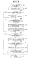
- Fig. 8 is a flow chart of a motor control program that describes the operation of the motor driving apparatus for use in the dishwasher in accordance with the present invention.
- a motor driving program is started in step 100, and setting of various parameters, e.g., a driving frequency, a ratio of V/f, and a reactive current is performed in step 101. Then, it is determined whether a motor's operation is a start-up operation in step 102, and, if so, a start-up control subroutine is executed in step 103.
- various parameters e.g., a driving frequency, a ratio of V/f, and a reactive current.
- the start-up control subroutine 103 is for linearly increasing driving frequency f from 0 to set frequency fs. Depending on driving frequency f, a V/f control and a setting value for reactive current Irs are varied. As for a pump load, the load torque is changed by the square of the rotation speed. Thus, a stable driving control can be performed by obtaining torque current Iq corresponding to a rotation speed, calculating Isin ⁇ and performing a driving control with reference to a control table.
- step 104 it is determined whether there exists a carrier signal interrupt in step 104. If there is a carrier signal interrupt, a carrier signal interrupt subroutine and a rotation speed control subroutine are carried out in step 105 and step 106, respectively.
- a program is started in step 200, and it is determined in step 201 whether count k of carrier synchronization signals ck is equal to the number of carriers kc within one period of motor driving frequency f. If they are identical, carrier count k is cleared in step 202. The number of carriers kc within one period of motor driving frequency f is obtained in advance at a time of setting the driving frequency.
- driving frequency f and its period T are set to be 269.3 Hz and 3.712 msec, respectively.
- carrier period Tc is 64 ⁇ sec (carrier frequency of 15.6 kHz)
- the number of pulses kc becomes 58.
- the count of the carrier synchronization signal is increased in step 203, and electrical angle ⁇ is calculated from the number of carriers k and phase ⁇ of one carrier period Tc in step 204.
- inverter output currents Iu, Iv and Iw are detected based on signals provided from the current detector 5 in step 205.
- three phase/two phase baseline axis coordinates transformation is performed by using Equation 2 to thereby obtain reactive current Ir and effective current Ia in step 206.
- Ir and Ia are stored in step 207.
- step 210 If calculated value Im is equal to or greater than over-current setting value Imax, driving of power semiconductors of inverter circuit 3 is ceased in step 210, to thereby stop the driving of the motor. Thereafter, an over-current abnormality flag is set in step 211.
- inverter output control signal Va generated from a rotation speed control subroutine is retrieved in step 212, and, in step 213, a two phase/three phase baseline axis coordinates inverse transformation is conducted by using Equation 5 to obtain phase control signals vu, vv and vw of the inverter. Subsequently, a PWM control is performed in step 214, and, in step 215, the process returns.
- Fig. 10 shows the rotation speed control subroutine. It is not necessary to perform the rotation speed control subroutine for every carrier signal but it may be conducted for every, e.g., two carrier signals. If a carrier frequency becomes an ultrasonic frequency, program processing time within one carrier period becomes critical, so that processes that should be conducted for every carrier signal, such as a phase calculation, a current detecting operation and a PWN control, and processes that need not be conducted for every carrier signal, such as a transformation of coordinates and a rotation speed control subroutine shown in Fig. 10 are distinguished from each other. Then, by dividing the processes that need not be executed for every carrier signal into a plurality of sub processes and performing them, a sequential program of dishwasher other than the motor control can be carried out.
- a carrier frequency becomes an ultrasonic frequency
- program processing time within one carrier period becomes critical, so that processes that should be conducted for every carrier signal, such as a phase calculation, a current detecting operation and a PWN control, and processes that need not be conducted for every carrier
- step 300 the rotation speed control subroutine is initiated in step 300, and setting value fs for driving frequency is called in step 301.
- setting value Irs for the reactive current corresponding to driving frequency setting value fs is called in step 302
- reactive current Ir obtained from the three phase/two phase base line axis coordinates transformation is called in step 303.
- setting value V/f for applied voltage constant is called in step 304.
- comparison of Irs with Ir is conducted to obtain error signal ⁇ ir, from which applied voltage constant kv is calculated in step 305.
- step 306 voltage signal applied to baseline axis Va is calculated from applied voltage constant setting value V/f and applied voltage constant kv obtained in step 305.
- step 308 the process returns.
- step 107 it is determined in step 107 whether the current process is a drain pump driving process. If so, motor current Im is detected in step 108, and it is determined in step 109 whether motor current Im is smaller than setting value Ima. If Im is smaller than Ima, an air inflow detection flag is set in step 110, and the motor driving is stopped in step 111. Then, in step 112, the process returns.
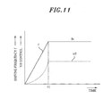
- Fig. 12 is for setting V/f, Isin ⁇ and air inflow detection current level Ima corresponding to a pump driving rotation speed.
- Fig. 13 when the pump sucks in air, a load on the motor is decreased, and thus torque current Iq1 is reduced accordingly, resulting in a reduction of voltage Vi1 applied to the motor.
- reactive current Ir is maintained to be constant, phase ⁇ 1 is increased and moved towards the q axis. As a result, an effective current of I1 is reduced.
- the rotation speed of motor may be lowered to thereby reduce the inflow of air. Further, since it may happen that cleaning efficiency is deteriorated if the amount of wash water is reduced, it is also preferable to reduce the inflow of air by way of increasing the quantity of wash water by supplying more water thereto while maintaining the rotation speed of motor. Further, both methods can be employed together.
- the inflow of air results in a reduction in the load on the motor, the voltage applied to the motor (inverter output voltage) and the motor current are decreased.
- the motor current is decreased, an operation for increasing a reactive current is performed.
- a current envelope may vibrate greatly, resulting in an increase of amplitude of current.
- the amplitude of current is rather reduced, and detection precision can be improved if the detection of the inflow of air is performed when the amplitude of current is reduced.
- the inflow of air can be detected by obtaining a difference between the maximum and the minimum of the current envelope as means for detecting a vibration of current or voltage.
- the motor driving apparatus for use in a dishwasher in accordance with the present invention performs a sensorless sine wave driving of a brushless DC motor by detecting a current of an inverter circuit by means of a low-price current detector.
- the motor can be reduced in its size and thickness at a reduced price, while enhancing the reliability thereof.
- a current can be detected while the influence from switching noises is reduced.
- a carrier frequency can be successively detected even when the carrier frequency is in a supersonic frequency range.
- an instantaneous detection of current can be achieved readily and the detection of the air inflow can be easily performed by observing a change in a motor current caused by a change in a load on the motor.
- the motor driving apparatus for use in a dishwasher in accordance with the present invention converts an AC power to a DC power by a rectification circuit, drives a motor by means of an inverter circuit, detects an output current of the inverter circuit by using a current detector to thereby perform a PWM control of the inverter circuit such that a set rotation speed of the motor is obtained, and controls a phase difference between an output voltage and the output current of the inverter circuit or a reactive current to have a predetermined value. Therefore, a highly efficient sensorless sine wave driving of motor becomes feasible.
- the present invention can be applied to drive a motor for a drying fan in a washing and drying machine of dishwasher, a motor for a drying fan in a washing and drying machine, a motor for a pump for bath water and the like.
Abstract
Description


Claims (7)
- An apparatus for driving a motor of a dishwasher comprising:wherein a phase difference between an output voltage and the output current of the inverter circuit or a reactive current is controlled to have a predetermined value.an AC power source;a rectification circuit for converting an AC power from the AC power source to a DC power;an inverter circuit for converting the DC power from the rectification circuit to an AC power;a motor driven by the inverter circuit to drive a wash pump and/or a drain pump;a current detector for detecting an output current of the inverter circuit; anda controller for performing a PWM (pulse width modulation) control of the inverter circuit based on an output signal of the current detector to thereby control the motor to rotate at a set rotation speed,
- The apparatus of claim 1, wherein the inverter circuit is configured as a three phase full-bridge inverter circuit including six transistors and six diodes, and the current detector includes shunt resistors respectively connected to negative potential terminals of lower arm transistors of the three phase full-bridge inverter circuit, wherein the output current of the inverter circuit is detected by detecting a current flowing through the shunt resistors.
- The apparatus of claim 1, wherein the motor is a position-sensorless brushless DC motor having a planar shape.
- The apparatus of claim 1, wherein the output current of the inverter circuit and an induced voltage of the motor are controlled to have a substantially identical phase by way of controlling the phase between the output voltage and the output current of the inverter circuit or the reactive current to have the predetermined value.
- The apparatus of claim 1, wherein the output current of the inverter circuit is controlled to lead the induced voltage of the motor by way of controlling the phase difference between the output voltage and the output current of the inverter circuit or the reactive current to have the predetermined value.
- The apparatus of claim 1, wherein the phase difference between the output voltage and the output current of the inverter circuit or the reactive current is controlled to have the predetermined value by way of detecting the output current of the inverter circuit by means of the current detector in synchronous with a switching period for the PWM control of the inverter circuit and comparing a value of the output current detected by the current detector with a value of an output current that is calculated and set in synchronous with the switching period.
- The apparatus of claim 1, wherein a wash pump operation or a drain pump operation is enabled by allowing the motor to make forward or backward rotations, and an inflow of air in the wash pump or the drain pump is detected if the output current of the inverter circuit falls below a preset value while driving the wash pump or the drain pump by controlling the motor to rotate at a set rotation speed.
Applications Claiming Priority (2)
| Application Number | Priority Date | Filing Date | Title |
|---|---|---|---|
| JP2003412988 | 2003-12-11 | ||
| JP2003412988A JP4363169B2 (en) | 2003-12-11 | 2003-12-11 | Dishwasher motor drive |
Publications (2)
| Publication Number | Publication Date |
|---|---|
| EP1542351A2 true EP1542351A2 (en) | 2005-06-15 |
| EP1542351A3 EP1542351A3 (en) | 2008-02-27 |
Family
ID=34510538
Family Applications (1)
| Application Number | Title | Priority Date | Filing Date |
|---|---|---|---|
| EP04028485A Withdrawn EP1542351A3 (en) | 2003-12-11 | 2004-12-01 | Motor driving apparatus for use in a dishwasher |
Country Status (6)
| Country | Link |
|---|---|
| US (1) | US7064517B2 (en) |
| EP (1) | EP1542351A3 (en) |
| JP (1) | JP4363169B2 (en) |
| KR (1) | KR100712247B1 (en) |
| CN (2) | CN2815266Y (en) |
| TW (1) | TWI302094B (en) |
Cited By (7)
| Publication number | Priority date | Publication date | Assignee | Title |
|---|---|---|---|---|
| EP2104222A1 (en) * | 2008-03-20 | 2009-09-23 | Electrolux Home Products Corporation N.V. | Method and device for controlling a brushless AC motor |
| WO2010112331A3 (en) * | 2009-04-02 | 2010-11-25 | BSH Bosch und Siemens Hausgeräte GmbH | Method for operating a water conducting household device |
| WO2011138221A3 (en) * | 2010-05-05 | 2011-12-29 | BSH Bosch und Siemens Hausgeräte GmbH | Pump device and water-bearing household device provided with said type of pump device |
| ITTO20111248A1 (en) * | 2011-12-30 | 2013-07-01 | Indesit Co Spa | DISHWASHER AND METHOD FOR DETECTING A FAILURE OF WATER INTO THE SAFE DISHWASHER |
| EP2629415A1 (en) * | 2011-03-30 | 2013-08-21 | Panasonic Corporation | Lead angle value setting method, motor driving control circuit, and brushless motor |
| US8793828B2 (en) | 2010-04-13 | 2014-08-05 | Whirlpool Corporation | Laundry treating appliance with automatic pump shutoff |
| CN112969825A (en) * | 2018-09-06 | 2021-06-15 | Lg电子株式会社 | Drain pump driving device and laundry treatment apparatus including the same |
Families Citing this family (46)
| Publication number | Priority date | Publication date | Assignee | Title |
|---|---|---|---|---|
| US7102323B2 (en) * | 2004-11-30 | 2006-09-05 | Honeywell International Inc. | High power density/limited DC link voltage synchronous motor drive |
| JP4682727B2 (en) * | 2005-07-13 | 2011-05-11 | パナソニック株式会社 | Motor drive device |
| KR100662434B1 (en) * | 2005-11-17 | 2007-01-02 | 엘지전자 주식회사 | Driving device in washing machine and washing machine with the same |
| JP4759422B2 (en) * | 2006-03-27 | 2011-08-31 | 日立アプライアンス株式会社 | Power converter system and washing machine using the same |
| JP4537341B2 (en) * | 2006-04-12 | 2010-09-01 | 三菱電機株式会社 | Dishwasher and dishwashing method |
| JP4383442B2 (en) | 2006-12-27 | 2009-12-16 | 三洋電機株式会社 | Motor control device and motor drive system |
| JP5061621B2 (en) * | 2007-01-25 | 2012-10-31 | パナソニック株式会社 | dishwasher |
| JP5061620B2 (en) * | 2007-01-25 | 2012-10-31 | パナソニック株式会社 | Pump device and dishwasher using the same |
| US7843156B2 (en) * | 2007-06-28 | 2010-11-30 | Gm Global Technology Operations, Inc. | Method and apparatus for active voltage control of electric motors |
| US8226374B2 (en) * | 2008-07-24 | 2012-07-24 | Nidec Motor Corporation | Variable motor drive system for a reservoir with circulating fluid |
| US20100139698A1 (en) * | 2008-12-09 | 2010-06-10 | General Electric Company | Staggered multi-mode spray arm wash system |
| US8092611B2 (en) * | 2009-01-29 | 2012-01-10 | General Electric Company | Method and system for dishwasher operation |
| CN101873078B (en) * | 2009-04-21 | 2012-11-21 | 比亚迪股份有限公司 | Controllable rectifying device and electromotor using the same |
| BRPI0902349A2 (en) * | 2009-07-22 | 2011-08-23 | Whirlpool Sa | control method for electric motors applied to cyclic loads |
| US8241018B2 (en) | 2009-09-10 | 2012-08-14 | Tyco Healthcare Group Lp | Compact peristaltic medical pump |
| JP5655367B2 (en) * | 2010-05-07 | 2015-01-21 | パナソニックIpマネジメント株式会社 | Motor drive device |
| JP5378323B2 (en) | 2010-08-09 | 2013-12-25 | 株式会社東芝 | Brushless motor drive circuit and brushless motor drive system |
| KR101741258B1 (en) * | 2010-09-02 | 2017-05-29 | 엘지전자 주식회사 | A control method of a dishwasher |
| US8436566B2 (en) * | 2011-02-02 | 2013-05-07 | Cooler Master Co., Ltd. | Multi-speed control apparatus for fan motor |
| US8644992B2 (en) * | 2011-05-05 | 2014-02-04 | General Electric Company | Method to improve washer motor efficiency and performance |
| WO2012167241A1 (en) | 2011-06-02 | 2012-12-06 | Black & Decker Inc. | Control system for a fastening power tool |
| EP2916708B1 (en) | 2012-11-08 | 2020-01-08 | Electrolux Home Products Corporation N.V. | Detecting filter clogging |
| PL2916707T3 (en) | 2012-11-08 | 2020-02-28 | Electrolux Home Products Corporation N.V. | Detecting operational state of a dishwasher |
| US9609997B2 (en) | 2013-07-09 | 2017-04-04 | Haier Us Appliance Solutions, Inc. | Systems and methods for detecting appliance pump cavitation or dry state |
| TWI505629B (en) * | 2013-07-10 | 2015-10-21 | Method for adjusting the efficiency of a synchronous machine | |
| KR101539862B1 (en) * | 2013-11-13 | 2015-07-27 | 삼성전기주식회사 | Apparatus and method for motor drive control, and motor system using the same |
| CN104092412B (en) * | 2014-06-30 | 2016-08-24 | 英特格灵芯片(天津)有限公司 | Method, device and the control system that the brushless electric machine phase advance angle upper limit sets |
| FR3023087B1 (en) * | 2014-06-30 | 2016-10-28 | Schneider Toshiba Inverter Europe Sas | CONTROL METHOD FOR STARTING A SYNCHRONOUS ELECTRIC MOTOR |
| CN104622407B (en) * | 2015-02-05 | 2017-06-23 | 佛山市顺德区美的洗涤电器制造有限公司 | A kind of dish-washing machine and its control method of washing and system |
| JP6516537B2 (en) * | 2015-04-10 | 2019-05-22 | 株式会社ミツバ | Motor drive device and control method of motor drive device |
| WO2016163398A1 (en) * | 2015-04-10 | 2016-10-13 | 株式会社ミツバ | Motor drive apparatus and method of controlling motor drive apparatus |
| JP6498501B2 (en) * | 2015-04-10 | 2019-04-10 | 株式会社ミツバ | Motor driving device and control method of motor driving device |
| US9840803B2 (en) | 2015-10-20 | 2017-12-12 | Haier Us Appliance Solutions, Inc. | Pump assembly for appliance |
| CN108430296B (en) | 2015-11-10 | 2022-01-14 | 伊莱克斯电器股份公司 | Method for determining the presence of process water in a circulation pump of an appliance for washing and rinsing goods, and appliance for washing and rinsing goods |
| WO2017088917A1 (en) | 2015-11-25 | 2017-06-01 | Electrolux Appliances Aktiebolag | Determining whether process water has been added to a sump of an appliance for washing and rinsing goods during interruption of appliance operation |
| PL3416534T3 (en) | 2016-02-15 | 2020-06-29 | Electrolux Appliances Aktiebolag | Process water flow detection in circulation pump |
| CN105863632B (en) * | 2016-06-14 | 2018-02-02 | 株洲中车时代电气股份有限公司 | A kind of control method and system of the frequency converter fluid drive of boom-type roadheader cut |
| KR101936476B1 (en) | 2016-12-14 | 2019-01-08 | 현대자동차주식회사 | Brushless DC electric motor driving control method of Electrical Water Pump |
| CN107013471B (en) * | 2017-01-13 | 2018-06-12 | 无锡雷利电子控制技术有限公司 | Half load detection method and detecting system, washing facility |
| WO2018153472A1 (en) | 2017-02-24 | 2018-08-30 | Electrolux Appliances Aktiebolag | Dishwasher, method and control system for handling clogging condition |
| KR102463316B1 (en) * | 2017-11-01 | 2022-11-04 | 엘지전자 주식회사 | Laundry treating appratus and controlling method thereof |
| CN107769662B (en) * | 2017-11-13 | 2020-04-21 | 苏州艾克威尔科技有限公司 | Control method of asynchronous motor |
| US10715052B2 (en) * | 2018-08-22 | 2020-07-14 | Caterpillar Inc. | Inverter topology |
| CN111358354A (en) * | 2018-12-26 | 2020-07-03 | 北京奇虎科技有限公司 | Sweeping robot and sweeping motor power supply circuit thereof |
| CN111820834B (en) * | 2019-04-15 | 2021-11-19 | 宁波方太厨具有限公司 | Dish washing machine cleaning system and automatic cleaning method |
| CN112790694B (en) * | 2019-11-14 | 2022-06-21 | 宁波方太厨具有限公司 | Cleaning machine and cleaning method |
Family Cites Families (20)
| Publication number | Priority date | Publication date | Assignee | Title |
|---|---|---|---|---|
| BR8805485A (en) * | 1988-10-17 | 1990-06-05 | Brasil Compressores Sa | ELECTRONIC CONTROL CIRCUIT FOR CURRENT MOTOR CONTINUES WITHOUT BRUSHES |
| JP3678558B2 (en) * | 1997-10-23 | 2005-08-03 | 三菱電機株式会社 | Control device for permanent magnet type synchronous motor |
| EP0945974B1 (en) * | 1998-03-23 | 2004-01-21 | Hitachi, Ltd. | Control apparatus of brushless motor and machine using brushless motor |
| JP3591314B2 (en) * | 1998-07-15 | 2004-11-17 | 株式会社日立製作所 | Control device for brushless motor and equipment using this control device |
| DE19846831B4 (en) * | 1998-10-10 | 2008-05-29 | Diehl Ako Stiftung & Co. Kg | Method and device for determining the rotor position of synchronous motors |
| JP2000152683A (en) * | 1998-11-13 | 2000-05-30 | Mitsubishi Heavy Ind Ltd | Method for controlling brushless dc motor |
| WO2000029660A1 (en) * | 1998-11-17 | 2000-05-25 | Fisher & Paykel Limited | Laundry machine |
| DE19860446A1 (en) * | 1998-12-28 | 2000-06-29 | Grundfos A S Bjerringbro | Method for controlling a voltage / frequency converter-controlled multi-phase permanent magnet motor |
| JP3483789B2 (en) * | 1999-02-22 | 2004-01-06 | 株式会社東芝 | Drive device for brushless DC motor |
| US6538404B2 (en) * | 2000-02-14 | 2003-03-25 | Sanyo Electric Co., Ltd. | Motor apparatus |
| JP3423270B2 (en) * | 2000-03-30 | 2003-07-07 | 三洋電機株式会社 | Drum type washing machine |
| WO2001079603A1 (en) * | 2000-04-19 | 2001-10-25 | Sanyo Electric Co., Ltd. | Drum type washing machine and its control method |
| US6778868B2 (en) * | 2000-09-12 | 2004-08-17 | Kabushiki Kaisha Toshiba | Remote control of laundry appliance |
| DE10063054A1 (en) * | 2000-12-18 | 2002-06-20 | Wilo Gmbh | Sensorless control method |
| TW584688B (en) * | 2001-06-06 | 2004-04-21 | Toshiba Corp | Washing machine |
| US6737828B2 (en) * | 2001-07-19 | 2004-05-18 | Matsushita Electric Industrial Co., Ltd. | Washing machine motor drive device |
| JP2003143890A (en) * | 2001-11-01 | 2003-05-16 | Hitachi Ltd | Direct-current brushless motor drive unit and method therefor |
| JP3651595B2 (en) * | 2001-12-13 | 2005-05-25 | 株式会社東芝 | Inverter device for washing machine and inverter device for washing dryer |
| JP3896845B2 (en) | 2001-12-25 | 2007-03-22 | 株式会社日立製作所 | dishwasher |
| DE10207232B4 (en) * | 2002-02-21 | 2005-11-17 | Diehl Ako Stiftung & Co. Kg | Circuit arrangement for controlling an electromotive drive, in particular pump drive, in a household appliance |
-
2003
- 2003-12-11 JP JP2003412988A patent/JP4363169B2/en not_active Expired - Fee Related
-
2004
- 2004-11-29 US US10/997,916 patent/US7064517B2/en not_active Expired - Fee Related
- 2004-12-01 EP EP04028485A patent/EP1542351A3/en not_active Withdrawn
- 2004-12-02 KR KR1020040100146A patent/KR100712247B1/en not_active IP Right Cessation
- 2004-12-07 CN CNU2004201174996U patent/CN2815266Y/en not_active Expired - Fee Related
- 2004-12-07 CN CNB200410100668XA patent/CN1306694C/en not_active Expired - Fee Related
- 2004-12-09 TW TW093138135A patent/TWI302094B/en not_active IP Right Cessation
Non-Patent Citations (1)
| Title |
|---|
| MATSUI N: "Sensorless operation of brushless DC motor drives", INDUSTRIAL ELECTRONICS, CONTROL, AND INSTRUMENTATION, 1993. PROCEEDING S OF THE IECON '93., INTERNATIONAL CONFERENCE ON MAUI, HI, USA 15-19 NOV. 1993, NEW YORK, NY, USA,IEEE, 15 November 1993 (1993-11-15), pages 739 - 744, XP010109131, ISBN: 978-0-7803-0891-6 * |
Cited By (11)
| Publication number | Priority date | Publication date | Assignee | Title |
|---|---|---|---|---|
| EP2104222A1 (en) * | 2008-03-20 | 2009-09-23 | Electrolux Home Products Corporation N.V. | Method and device for controlling a brushless AC motor |
| WO2009115330A1 (en) * | 2008-03-20 | 2009-09-24 | Electrolux Home Products Corporation N.V. | Method and device for controlling a brushless ac motor |
| WO2010112331A3 (en) * | 2009-04-02 | 2010-11-25 | BSH Bosch und Siemens Hausgeräte GmbH | Method for operating a water conducting household device |
| US8793828B2 (en) | 2010-04-13 | 2014-08-05 | Whirlpool Corporation | Laundry treating appliance with automatic pump shutoff |
| WO2011138221A3 (en) * | 2010-05-05 | 2011-12-29 | BSH Bosch und Siemens Hausgeräte GmbH | Pump device and water-bearing household device provided with said type of pump device |
| EP2629415A1 (en) * | 2011-03-30 | 2013-08-21 | Panasonic Corporation | Lead angle value setting method, motor driving control circuit, and brushless motor |
| EP2629415A4 (en) * | 2011-03-30 | 2014-01-01 | Panasonic Corp | Lead angle value setting method, motor driving control circuit, and brushless motor |
| US8692492B2 (en) | 2011-03-30 | 2014-04-08 | Panasonic Corporation | Lead angle value setting method, motor driving control circuit, and brushless motor |
| ITTO20111248A1 (en) * | 2011-12-30 | 2013-07-01 | Indesit Co Spa | DISHWASHER AND METHOD FOR DETECTING A FAILURE OF WATER INTO THE SAFE DISHWASHER |
| CN112969825A (en) * | 2018-09-06 | 2021-06-15 | Lg电子株式会社 | Drain pump driving device and laundry treatment apparatus including the same |
| CN112969825B (en) * | 2018-09-06 | 2023-11-03 | Lg电子株式会社 | Drainage pump driving device and washing treatment equipment comprising same |
Also Published As
| Publication number | Publication date |
|---|---|
| CN1627625A (en) | 2005-06-15 |
| EP1542351A3 (en) | 2008-02-27 |
| TW200528057A (en) | 2005-09-01 |
| KR20050058191A (en) | 2005-06-16 |
| JP2005168797A (en) | 2005-06-30 |
| CN2815266Y (en) | 2006-09-13 |
| TWI302094B (en) | 2008-10-21 |
| US20050127865A1 (en) | 2005-06-16 |
| JP4363169B2 (en) | 2009-11-11 |
| US7064517B2 (en) | 2006-06-20 |
| CN1306694C (en) | 2007-03-21 |
| KR100712247B1 (en) | 2007-04-27 |
Similar Documents
| Publication | Publication Date | Title |
|---|---|---|
| US7064517B2 (en) | Motor driving apparatus for use in a dishwasher | |
| KR100659423B1 (en) | Motor driving device | |
| KR100681081B1 (en) | Apparatus for driving motor of dishwasher | |
| US8424347B2 (en) | Washer dryer | |
| KR100432962B1 (en) | Washer | |
| JP3610897B2 (en) | INVERTER DEVICE, COMPRESSOR DRIVE DEVICE, REFRIGERATION / AIR CONDITIONER, INVERTER DEVICE CONTROL METHOD | |
| US20070013325A1 (en) | Motor drive unit | |
| EP3849073A1 (en) | Catch spin method for permanent magnet synchronous motor with sensorless field oriented control | |
| KR20030009217A (en) | Washing machine motor drive device | |
| KR101709475B1 (en) | Motor driving device and laundry treatment machine including the same | |
| CN113422552A (en) | Motor controller and method for monitoring demagnetization | |
| JP2006006766A (en) | Motor driving device of dishwasher | |
| JPWO2020021681A1 (en) | Motor drive device and refrigeration cycle applicable equipment | |
| KR101635551B1 (en) | Motor driving device and dish washing machine including the same | |
| JP4406185B2 (en) | Washing machine | |
| JP2018088741A (en) | Motor driving device and control method thereof | |
| JP2005312227A (en) | Pump or fan motor driving apparatus | |
| JP2005057858A (en) | Motor driving device and motor driving device of dish washer | |
| JP2005348569A (en) | Motor driver | |
| JPWO2021038817A1 (en) | Motor drive device, motor drive system and refrigeration cycle device | |
| WO2018141394A1 (en) | Household appliance with brushless dc motor sensorless control scheme | |
| JP2005253163A (en) | Motor driving unit | |
| Li et al. | Sensorless control and PMSM drive system for compressor applications | |
| JP4258085B2 (en) | Dishwasher control device | |
| JP2001058096A (en) | Controller for washing machine |
Legal Events
| Date | Code | Title | Description |
|---|---|---|---|
| PUAI | Public reference made under article 153(3) epc to a published international application that has entered the european phase |
Free format text: ORIGINAL CODE: 0009012 |
|
| AK | Designated contracting states |
Kind code of ref document: A2 Designated state(s): AT BE BG CH CY CZ DE DK EE ES FI FR GB GR HU IE IS IT LI LT LU MC NL PL PT RO SE SI SK TR |
|
| AX | Request for extension of the european patent |
Extension state: AL BA HR LV MK YU |
|
| RIN1 | Information on inventor provided before grant (corrected) |
Inventor name: YOSHIOKA, KANEHARU Inventor name: NAKATA, HIDEKI Inventor name: SUZUKI, MASAHIRO Inventor name: KIUCHI, MITSUYUKI |
|
| PUAL | Search report despatched |
Free format text: ORIGINAL CODE: 0009013 |
|
| AK | Designated contracting states |
Kind code of ref document: A3 Designated state(s): AT BE BG CH CY CZ DE DK EE ES FI FR GB GR HU IE IS IT LI LT LU MC NL PL PT RO SE SI SK TR |
|
| AX | Request for extension of the european patent |
Extension state: AL BA HR LV MK YU |
|
| 17P | Request for examination filed |
Effective date: 20080618 |
|
| AKX | Designation fees paid |
Designated state(s): DE ES FR GB IT |
|
| RAP1 | Party data changed (applicant data changed or rights of an application transferred) |
Owner name: PANASONIC CORPORATION |
|
| 17Q | First examination report despatched |
Effective date: 20100415 |
|
| STAA | Information on the status of an ep patent application or granted ep patent |
Free format text: STATUS: THE APPLICATION IS DEEMED TO BE WITHDRAWN |
|
| 18D | Application deemed to be withdrawn |
Effective date: 20160701 |