JP4363169B2 - Dishwasher motor drive - Google Patents
Dishwasher motor drive Download PDFInfo
- Publication number
- JP4363169B2 JP4363169B2 JP2003412988A JP2003412988A JP4363169B2 JP 4363169 B2 JP4363169 B2 JP 4363169B2 JP 2003412988 A JP2003412988 A JP 2003412988A JP 2003412988 A JP2003412988 A JP 2003412988A JP 4363169 B2 JP4363169 B2 JP 4363169B2
- Authority
- JP
- Japan
- Prior art keywords
- motor
- current
- inverter circuit
- phase
- output
- Prior art date
- Legal status (The legal status is an assumption and is not a legal conclusion. Google has not performed a legal analysis and makes no representation as to the accuracy of the status listed.)
- Expired - Fee Related
Links
- 238000001514 detection method Methods 0.000 claims description 34
- 238000005406 washing Methods 0.000 claims description 17
- 238000004140 cleaning Methods 0.000 claims description 11
- 230000002441 reversible effect Effects 0.000 claims description 9
- 238000000034 method Methods 0.000 description 23
- 238000006243 chemical reaction Methods 0.000 description 16
- 238000010586 diagram Methods 0.000 description 10
- XLYOFNOQVPJJNP-UHFFFAOYSA-N water Substances O XLYOFNOQVPJJNP-UHFFFAOYSA-N 0.000 description 10
- 230000007423 decrease Effects 0.000 description 7
- 239000003990 capacitor Substances 0.000 description 5
- 230000003111 delayed effect Effects 0.000 description 4
- 230000003247 decreasing effect Effects 0.000 description 3
- 230000001360 synchronised effect Effects 0.000 description 3
- 238000004804 winding Methods 0.000 description 3
- 230000003321 amplification Effects 0.000 description 2
- 230000000694 effects Effects 0.000 description 2
- 238000003199 nucleic acid amplification method Methods 0.000 description 2
- 230000004044 response Effects 0.000 description 2
- 230000005856 abnormality Effects 0.000 description 1
- 239000000969 carrier Substances 0.000 description 1
- 238000001035 drying Methods 0.000 description 1
- 230000007935 neutral effect Effects 0.000 description 1
- 230000010355 oscillation Effects 0.000 description 1
- 238000005086 pumping Methods 0.000 description 1
- 230000004043 responsiveness Effects 0.000 description 1
- 239000004065 semiconductor Substances 0.000 description 1
- 239000008400 supply water Substances 0.000 description 1
- 239000008399 tap water Substances 0.000 description 1
- 235000020679 tap water Nutrition 0.000 description 1
- 230000009466 transformation Effects 0.000 description 1
- 230000003313 weakening effect Effects 0.000 description 1
Images


Classifications
-
- H—ELECTRICITY
- H02—GENERATION; CONVERSION OR DISTRIBUTION OF ELECTRIC POWER
- H02P—CONTROL OR REGULATION OF ELECTRIC MOTORS, ELECTRIC GENERATORS OR DYNAMO-ELECTRIC CONVERTERS; CONTROLLING TRANSFORMERS, REACTORS OR CHOKE COILS
- H02P7/00—Arrangements for regulating or controlling the speed or torque of electric DC motors
- H02P7/06—Arrangements for regulating or controlling the speed or torque of electric DC motors for regulating or controlling an individual dc dynamo-electric motor by varying field or armature current
- H02P7/18—Arrangements for regulating or controlling the speed or torque of electric DC motors for regulating or controlling an individual dc dynamo-electric motor by varying field or armature current by master control with auxiliary power
- H02P7/34—Arrangements for regulating or controlling the speed or torque of electric DC motors for regulating or controlling an individual dc dynamo-electric motor by varying field or armature current by master control with auxiliary power using Ward-Leonard arrangements
-
- A—HUMAN NECESSITIES
- A47—FURNITURE; DOMESTIC ARTICLES OR APPLIANCES; COFFEE MILLS; SPICE MILLS; SUCTION CLEANERS IN GENERAL
- A47L—DOMESTIC WASHING OR CLEANING; SUCTION CLEANERS IN GENERAL
- A47L15/00—Washing or rinsing machines for crockery or tableware
- A47L15/42—Details
- A47L15/4214—Water supply, recirculation or discharge arrangements; Devices therefor
- A47L15/4225—Arrangements or adaption of recirculation or discharge pumps
-
- A—HUMAN NECESSITIES
- A47—FURNITURE; DOMESTIC ARTICLES OR APPLIANCES; COFFEE MILLS; SPICE MILLS; SUCTION CLEANERS IN GENERAL
- A47L—DOMESTIC WASHING OR CLEANING; SUCTION CLEANERS IN GENERAL
- A47L15/00—Washing or rinsing machines for crockery or tableware
- A47L15/42—Details
-
- A—HUMAN NECESSITIES
- A47—FURNITURE; DOMESTIC ARTICLES OR APPLIANCES; COFFEE MILLS; SPICE MILLS; SUCTION CLEANERS IN GENERAL
- A47L—DOMESTIC WASHING OR CLEANING; SUCTION CLEANERS IN GENERAL
- A47L15/00—Washing or rinsing machines for crockery or tableware
- A47L15/42—Details
- A47L15/46—Devices for the automatic control of the different phases of cleaning ; Controlling devices
-
- H—ELECTRICITY
- H02—GENERATION; CONVERSION OR DISTRIBUTION OF ELECTRIC POWER
- H02P—CONTROL OR REGULATION OF ELECTRIC MOTORS, ELECTRIC GENERATORS OR DYNAMO-ELECTRIC CONVERTERS; CONTROLLING TRANSFORMERS, REACTORS OR CHOKE COILS
- H02P6/00—Arrangements for controlling synchronous motors or other dynamo-electric motors using electronic commutation dependent on the rotor position; Electronic commutators therefor
- H02P6/08—Arrangements for controlling the speed or torque of a single motor
-
- H—ELECTRICITY
- H02—GENERATION; CONVERSION OR DISTRIBUTION OF ELECTRIC POWER
- H02P—CONTROL OR REGULATION OF ELECTRIC MOTORS, ELECTRIC GENERATORS OR DYNAMO-ELECTRIC CONVERTERS; CONTROLLING TRANSFORMERS, REACTORS OR CHOKE COILS
- H02P6/00—Arrangements for controlling synchronous motors or other dynamo-electric motors using electronic commutation dependent on the rotor position; Electronic commutators therefor
- H02P6/20—Arrangements for starting
- H02P6/21—Open loop start
-
- A—HUMAN NECESSITIES
- A47—FURNITURE; DOMESTIC ARTICLES OR APPLIANCES; COFFEE MILLS; SPICE MILLS; SUCTION CLEANERS IN GENERAL
- A47L—DOMESTIC WASHING OR CLEANING; SUCTION CLEANERS IN GENERAL
- A47L15/00—Washing or rinsing machines for crockery or tableware
- A47L15/0018—Controlling processes, i.e. processes to control the operation of the machine characterised by the purpose or target of the control
- A47L15/0052—Noise reduction
Description
本発明は家庭用の食器を洗浄する食器洗い機に関するものである。 The present invention relates to a dishwasher for washing household dishes.
従来、この種の食器洗い機のモータ駆動装置は、インバータによりセンサレスブラシレスモータを駆動することによりポンプモータを小型化する必要があった(例えば、特許文献1参照)。
しかしながら、前記従来の構成では、位置検出のためにモータ誘起電圧を検出する必要があるので、120度通電、あるいは方形波駆動と呼ばれるモータ駆動方法を採用しているためモータ電流の波形歪みが大きくモータ騒音が増加する課題があった。また、センサレス駆動ではなく位置センサ信号により駆動する場合には、モータに位置センサを設ける必要があり、モータ厚みが大きくなり、モータの信頼性が低下して高価格となる課題があった。 However, in the conventional configuration, since it is necessary to detect the motor induced voltage for position detection, a motor driving method called 120-degree energization or square wave driving is adopted, so that the waveform distortion of the motor current is large. There was a problem that motor noise increased. Further, in the case of driving by position sensor signal instead of sensorless driving, it is necessary to provide a position sensor in the motor, resulting in a problem that the thickness of the motor is increased, the reliability of the motor is lowered and the cost is increased.
本発明は、上記従来の課題を解決するもので、ポンプモータをセンサレス正弦波駆動することによりモータ騒音を低下させ、位置センサをなくすことよりモータを小型化、薄型化、低価格化して信頼性を向上させることを目的としている。 The present invention solves the above-mentioned conventional problems. The motor noise is reduced by driving the pump motor with a sensorless sine wave, and the motor is reduced in size, thickness, and cost by eliminating the position sensor. It aims to improve.
上記従来の課題を解決するために、本発明の食器洗い機のモータ駆動装置は、交流電力を整流回路により直流電力に変換し、洗浄ポンプ、あるいは排水ポンプを駆動するモータをインバータ回路により駆動し、インバータ回路の出力電流を電流検出手段により検出して設定回転数となるようにインバータ回路をPWM制御し、モータの印加電圧と前記モータの電流Iとの位相差をφとし、そのモータの電流Iの無効電流成分Isinφを無効電流とし、制御手段が、設定回転数におけるモータ負荷のトルク電流に応じた所定値に無効電流を設定し、設定回転数において無効電流が所定値となるように制御することにより、インバータ回路の出力電圧と出力電流との位相を制御するようにしたものである。
In order to solve the above-mentioned conventional problems, the motor driving device of the dishwasher of the present invention converts AC power into DC power by a rectifier circuit, and drives a motor that drives a washing pump or a drainage pump by an inverter circuit, and PWM controlling the inverter circuit so that the output current of the inverter circuit becomes the set rotational speed is detected by the current detecting means, a phase difference between the applied voltage motors and current I of the motor as phi, the motor The reactive current component Isinφ of the current I is set as the reactive current, and the control means sets the reactive current to a predetermined value corresponding to the torque current of the motor load at the set rotational speed so that the reactive current becomes a predetermined value at the set rotational speed. Thus, the phase between the output voltage and the output current of the inverter circuit is controlled.
本発明の食器洗い機のモータ駆動装置は、設定回転数におけるモータ負荷のトルク電流に応じた無効電流を流すことによりDCブラシレスモータ(同期モータ)をセンサレス正弦波駆動するようにしたものであり、位置センサを無くしても高効率運転が可能であり、モータ騒音を減らし、位置センサを無くしてモータを小型化でき、信頼性向上と低価格化を実現できる。 The motor driving device of the dishwasher of the present invention is a sensorless sine wave drive of a DC brushless motor (synchronous motor) by flowing an ineffective current corresponding to the torque current of the motor load at the set rotational speed, High-efficiency operation is possible without sensors, reducing motor noise, minimizing motors by eliminating position sensors, and improving reliability and reducing costs.
第1の発明は、交流電源と、前記交流電源の交流電力を直流電力に変換する整流回路と、前記整流回路の直流電力を交流電力に変換するインバータ回路と、前記インバータ回路により駆動され洗浄ポンプ、あるいは排水ポンプを駆動するモータと、前記インバータ回路の出力電流を検出する電流検出手段と、前記電流検出手段の出力信号により前記インバータ回路をPWM制御して設定回転数となるように前記モータを制御する制御手段とを備え、前記モータの印加電圧と前記モータの電流Iとの位相差をφとし、前記モータの電流Iの無効電流成分Isinφを無効電流とし、前記制御手段は、設定回転数におけるモータ負荷のトルク電流に応じた所定値に前記無効電流を設定し、前記設定回転数において前記無効電流が前記所定値となるように制御することにより、前記インバータ回路の出力電圧と出力電流との位相を制御するようにしたもので、位置センサを無くしても高効率運転が可能であり、モータ騒音を減らし、位置センサを無くしてモータを小型化でき、信頼性向上と低価格化を実現できる。 A first invention is an AC power source, a rectifier circuit that converts AC power of the AC power source into DC power, an inverter circuit that converts DC power of the rectifier circuit into AC power, and a cleaning pump driven by the inverter circuit Or a motor for driving the drainage pump, a current detection means for detecting the output current of the inverter circuit, and the motor so that the inverter circuit is PWM-controlled by the output signal of the current detection means to obtain a set rotational speed. and control means for controlling the phase difference between the current I of the applied voltage before Symbol motor motor and phi, and reactive current reactive current component Isinφ of the current I of the motor, said control means sets The reactive current is set to a predetermined value according to the torque current of the motor load at the rotational speed, and the reactive current becomes the predetermined value at the set rotational speed. By controlling in this way, the phase of the output voltage and output current of the inverter circuit is controlled, and high-efficiency operation is possible without the position sensor, reducing motor noise and eliminating the position sensor. The motor can be downsized, improving reliability and reducing price.
第2の発明は、第1の発明におけるインバータ回路は、6ヶのトランジスタとダイオードよりなる3相フルブリッジインバータ回路より構成し、電流検出手段は前記3相フルブリッジインバータ回路の下アームトランジスタの負電位側端子にそれぞれ接続したシャント抵抗より構成し、前記シャント抵抗に流れる電流を検出することにより前記インバータ回路の出力電流を検出するようにしたもので、直流成分の検出が容易となり、低価格のシャント抵抗により電流検出手段を構成できるので、電流検出手段を小型でき、低価格のセンサレスモータ駆動装置を実現できる。 According to a second invention, the inverter circuit in the first invention is constituted by a three-phase full-bridge inverter circuit comprising six transistors and a diode, and the current detection means is a negative arm transistor of the lower arm transistor of the three-phase full-bridge inverter circuit. It is composed of shunt resistors connected to the potential side terminals respectively, and the output current of the inverter circuit is detected by detecting the current flowing through the shunt resistor. Since the current detection means can be constituted by a shunt resistor, the current detection means can be reduced in size and a low-cost sensorless motor drive device can be realized.
第3の発明は、第1の発明におけるモータは、扁平状の位置センサレスDCブラシレスモータより構成するようにしたものであり、DCブラシレスモータにより構成することによりモータを小型化でき、さらに、位置センサが無いのでモータを扁平形状にすることができ、洗浄槽底部のモータ等装着容積を減らすことが可能となり、食器を配設する洗浄槽容積を大きくできコンパクト大容量の食器洗い機を実現できる。 According to a third invention, the motor according to the first invention is constituted by a flat position sensorless DC brushless motor, and the motor can be miniaturized by being constituted by a DC brushless motor. Therefore, the motor can be flattened, the mounting volume of the motor at the bottom of the washing tank can be reduced, the volume of the washing tank in which the dishes are arranged can be increased, and a compact and large-capacity dishwasher can be realized.
第4の発明は、第1の発明においてインバータ回路の出力電圧と出力電流との位相、あるいは無効電流が所定値となるように制御することにより前記インバータ回路の出力電流と前記モータの誘起電圧との位相がほぼ同位相となるように制御するようにしたものであり、モータ誘起電圧位相とモータ電流位相をほぼ同位相とすることによりモータ電流を減らして最大効率運転が可能となり、モータの温度上昇を減らすことができるのでモータの小型化、扁平化が可能となり、モータ装着容積を減らし、食器を配設する洗浄槽容積を大きくできコンパクト大容量、低価格の食器洗い機が実現できる。 According to a fourth invention, in the first invention, the output current of the inverter circuit and the induced voltage of the motor are controlled by controlling the phase of the output voltage and output current of the inverter circuit or the reactive current to be a predetermined value. The motor induced voltage phase and the motor current phase are set to be approximately the same phase, so that the motor current can be reduced and maximum efficiency operation is possible. Since the rise can be reduced, the motor can be reduced in size and flattened, the motor mounting volume can be reduced, the volume of the washing tank in which the dishes are arranged can be increased, and a compact large-capacity, low-cost dishwasher can be realized.
第5の発明は、第1の発明においてインバータ回路の出力電圧と出力電流との位相、あるいは無効電流が所定値となるように制御することにより前記モータの誘起電圧に対する前記インバータ回路の出力電流位相が進み角となるように制御するようにしたものであり、負荷変動により電流位相が変動しても誘起電圧に対する電流位相が遅れになってトルクが減少して脱調することがなくなり制御が安定化するので、ポンプのエア噛みのような急激な負荷変動に対しても安定に動作させることができると同時に弱め界磁制御により極数の多いモータにおいても高速運転が可能となる。 According to a fifth invention, in the first invention, the phase of the output voltage and output current of the inverter circuit, or the output current phase of the inverter circuit with respect to the induced voltage of the motor by controlling the reactive current to be a predetermined value. Is controlled so that the lead angle becomes the lead angle, and even if the current phase fluctuates due to load fluctuations, the current phase with respect to the induced voltage is delayed and the torque does not decrease and step out. Therefore, it is possible to stably operate against sudden load fluctuations such as pumping air, and at the same time, it is possible to operate at high speed even in a motor with a large number of poles by field-weakening control.
第6の発明は、第1の発明においてインバータ回路をPWM制御するスイッチング周期に同期して電流検出手段により前記インバータ回路の出力電流を検出し、前記電流検出手段により検出した電流値とスイッチング周期に同期して演算設定した出力電流値とを比較することにより前記インバータ回路の出力電圧と出力電流との位相、あるいは無効電流の瞬時値が所定値となるように制御するようにしたので、モータ駆動周波数よりも高いキャリヤ周波数でモータ電流位相や無効電流、あるいは電流絶対値検出が可能となり、モータ制御応答時間を早くして負荷変動に追従できるので、ポンプのエア噛みのような急激な負荷変動に対しても安定に動作させることができる。 In a sixth aspect of the invention, the output current of the inverter circuit is detected by the current detection means in synchronization with the switching period for PWM control of the inverter circuit in the first invention, and the current value detected by the current detection means and the switching period are detected. By comparing the output current value calculated and set synchronously, the phase of the output voltage and output current of the inverter circuit or the instantaneous value of the reactive current is controlled to be a predetermined value. The motor current phase, reactive current, or current absolute value can be detected at a carrier frequency higher than the frequency, and the motor control response time can be accelerated to follow load fluctuations. In contrast, it can be stably operated.
第7の発明は、第1の発明においてモータを正回転、あるいは逆回転に制御して洗浄ポンプ動作、あるいは排水ポンプ動作が可能となるようし、前記ポンプ駆動時に前記モータを設定回転数に制御しインバータ回路出力電流が所定値以下になると前記ポンプのエア噛み検知判定するようにしたので、エア噛み検知判定時の騒音増加を防ぐために、洗浄運転あるいはすすぎ運転時には回転数を減らすか水量を増やすことができ、排水運転時にはポンプ動作を一時停止して洗浄槽下部に洗浄水が溜まるまで待ち、再度排水ポンプを駆動することにより運転時間を減らし騒音発生を減らすことが可能となる。 According to a seventh aspect of the present invention, in the first aspect of the invention, the motor is controlled to rotate forward or reverse so that the washing pump operation or the drainage pump operation can be performed, and the motor is controlled to a set rotational speed when the pump is driven. When the inverter circuit output current falls below a predetermined value, the air-clogging detection determination of the pump is made. Therefore, in order to prevent an increase in noise during the air-clogging detection determination, the rotation speed is decreased or the amount of water is increased during washing operation or rinsing operation. In the drainage operation, it is possible to temporarily stop the pump operation, wait until the washing water accumulates in the lower part of the washing tank, and drive the drainage pump again to reduce the operation time and reduce the generation of noise.
(実施の形態1)
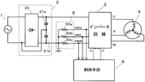
図1は、本発明の第1の実施の形態における食器洗い機のモータ駆動装置のブロック図を示すものである。
(Embodiment 1)
FIG. 1 is a block diagram of a motor driving device for a dishwasher according to a first embodiment of the present invention.
図1において、交流電源1より整流回路2に交流電力を加えて直流電力に変換し、インバータ回路3により直流電力を3相交流電力に変換してモータ4を駆動する。整流回路2は、全波整流回路20の直流出力端子にコンデンサ21a、21bを直列接続し、コンデンサ21a、21bの接続点を交流電源入力の一方の端子に接続して直流倍電圧回路を構成し、インバータ回路3への印加電圧を高くする。インバータ回路3の負電圧側に電流検出手段5を接続し、インバータ回路3の3相各下アームに流れる電流を検出することによりインバータ回路3の出力電流、すなわち、モータ4の各相電流を検出する。
In FIG. 1, AC power is applied to a
制御手段6は、電流検出手段5の出力信号よりインバータ回路3の出力電流を演算し、設定回転数に応じた所定周波数、所定電圧を印加してモータ4を回転駆動するものであり、モータ負荷に応じて出力電圧に対する出力電流位相、あるいは無効電流となるように制御することにより設定同期速度でモータ4を回転駆動できる。
The control means 6 calculates the output current of the
図2はインバータ回路3の詳細な回路図であり、6個のトランジスタとダイオードよりなる3相フルブリッジインバータ回路により構成している。ここで、3相アームの1つのU相アーム30Aについて説明すると、絶縁ゲートバイポーラトランジスタ(以下、IGBTと略す)よりなる上アームトランジスタ31a1と逆並列ダイオード32a1の並列接続体と、IGBTよりなる下アームトランジスタ31a2と逆並列ダイオード32a2の並列接続体を直列に接続し、上アームトランジスタ31a1のコレクタ端子は直流電源の正電位端子Lpに接続し、上アームトランジスタ31a1のエミッタ端子は出力端子Uに接続し、下アームトランジスタ31a2のエミッタ端子は電流検出手段5を構成するシャント抵抗50aを介して直流電源の負電位側端子Lnに接続する。
FIG. 2 is a detailed circuit diagram of the
上アームトランジスタ31a1は上アーム駆動信号Upに応じて上アームゲート駆動回路33a1により駆動され、下アームトランジスタ31a2は下アーム駆動信号Unに応じて下アームゲート駆動回路33a2によりオンオフスイッチング制御される。上アームゲート駆動回路33a1は、微分信号によりセットリセットされるRSフリップフロップ回路を内蔵し、上アーム駆動信号Upの立ち上がりで上アームトランジスタ31a1をオン動作させ、上アーム駆動信号Upの立ち下がりで上アームトランジスタ31a1をオフ動作させる。下アームゲート駆動回路33a2にはRSフリップフロップ回路は不必要であり、内蔵していない。 The upper arm transistor 31a1 is driven by the upper arm gate drive circuit 33a1 in accordance with the upper arm drive signal Up, and the lower arm transistor 31a2 is subjected to on / off switching control by the lower arm gate drive circuit 33a2 in accordance with the lower arm drive signal Un. The upper arm gate drive circuit 33a1 incorporates an RS flip-flop circuit that is set and reset by a differential signal, turns on the upper arm transistor 31a1 at the rise of the upper arm drive signal Up, and rises at the fall of the upper arm drive signal Up. The arm transistor 31a1 is turned off. The lower arm gate drive circuit 33a2 does not need an RS flip-flop circuit and does not incorporate it.
IGBTのゲート印加電圧は10〜15V必要であり、下アームトランジスタ31a2をオンさせると、15Vの直流電源の+端子B1よりブートストラップ抵抗34a、ブートストラップダイオード35aを介してブートストラップコンデンサ36aが充電されるので、ブートストラップコンデンサ36aの蓄積エネルギーにより上アームトランジスタ31a1をオンオフスイッチングできる。また、下アームの逆並列ダイオード32a2が導通した場合にも同様にブートストラップコンデンサ36aが充電される。
The gate application voltage of the IGBT needs 10 to 15V. When the lower arm transistor 31a2 is turned on, the
V相アーム30B、W相アーム30Cも同様の接続であり、各アームの下アームトランジスタのエミッタ端子は電流検出手段5を構成するシャント抵抗50b、50cに接続し、シャント抵抗50b、50cの他方の端子は直流電源負電位端子Lnに接続している。IGBT、あるいはパワーMOSFETにより下アームトランジスタを構成すると、ゲート電圧を制御することによりスイッチング制御できるので、IGBTの場合はエミッタ端子、パワーMOSFETの場合にはソース端子に接続するシャント抵抗の電圧が1V以下となるように抵抗値を選定すればスイッチング動作にはほとんど影響することなく電圧制御によりオンオフスイッチング制御でき、シャント抵抗50a、50b、50cの電圧veu、vev、vewを検出することによりインバータ回路出力電流、すなわちモータ電流を検出できる特徴がある。
The V-
図3は、インバータ回路出力電流の検出タイミングを示し、三角波変調によりPWM制御して、スイッチングノイズの影響を減らすために上下アームIGBTのスイッチングタイミングをはずして高速A/D変換してマイクロコンピュータ等のモータ制御プロセッサにより電流検出する。 FIG. 3 shows the detection timing of the inverter circuit output current, PWM control is performed by triangular wave modulation, the switching timing of the upper and lower arm IGBTs is removed to reduce the influence of switching noise, and high-speed A / D conversion is performed to Current detection is performed by a motor control processor.
図3において、ckは三角波変調信号Vtのピーク値すなわち時間t3にて発生させる同期信号であり、vuはU相電圧制御信号で、三角波変調信号VtとU相電圧制御信号vuを比較してU相上アームトランジスタ31a1の駆動信号UpとU相下アームトランジスタ31a2の駆動信号Unを発生させる。t1〜t2区間、t5〜t6区間は上下アームトランジスタの非導通期間でデッドタイムΔtと呼び、A/D変換タイミングは、上アームトランジスタがオフで下アームトランジスタがオンとなる時間t3、あるいは、時間t3からデッドタイムΔt時間ずらした時間t4の範囲内で行うとよい。 In FIG. 3, ck is a peak value of the triangular wave modulation signal Vt, that is, a synchronization signal generated at time t3, vu is a U-phase voltage control signal, and the triangular wave modulation signal Vt and the U-phase voltage control signal vu are compared with each other. A drive signal Up for the phase upper arm transistor 31a1 and a drive signal Un for the U phase lower arm transistor 31a2 are generated. The period between t1 and t2 and the period between t5 and t6 is called the dead time Δt in the non-conducting period of the upper and lower arm transistors, and the A / D conversion timing is the time t3 when the upper arm transistor is off and the lower arm transistor is on, It may be performed within a range of time t4 that is shifted from t3 by dead time Δt.
図4は、本発明による制御手段のブロック図で、マイクロコンピュータ、あるいはディジタルシグナルプロセッサ等の高速プロセッサによりセンサレス正弦波駆動を実現するものである。 FIG. 4 is a block diagram of the control means according to the present invention, in which sensorless sine wave driving is realized by a high-speed processor such as a microcomputer or a digital signal processor.
基本的な制御方法について図5のベクトル図を用いて説明する。図5は、ロータ表面に永久磁石を設けた表面永久磁石モータ(略してSPMモータ)のd−q座標系のベクトル図であり、モータ誘起電圧Vrはq軸と同軸となり、誘起電圧Vrは誘起電圧定数krと回転数N、すなわちモータ駆動周波数fに比例する。言い換えれば、モータ誘起電圧Vrと周波数fの比(Vr/f)は常に一定となる。 A basic control method will be described with reference to the vector diagram of FIG. FIG. 5 is a vector diagram of the dq coordinate system of a surface permanent magnet motor (abbreviated as SPM motor) having a permanent magnet on the rotor surface. The motor induced voltage Vr is coaxial with the q axis, and the induced voltage Vr is induced. It is proportional to the voltage constant kr and the rotation speed N, that is, the motor drive frequency f. In other words, the ratio (Vr / f) between the motor induced voltage Vr and the frequency f is always constant.
モータ電流Iをq軸と同軸に制御するとベクトル制御になるが、q軸は検出できないので、角度γ進角していると仮定する。モータの電圧方程式は式1で表現されるので、駆動周波数fが固定された場合、d−q座標系においては、電流ベクトルIを固定するとモータ印加電圧ベクトルViが固定される。逆に、モータ印加電圧ベクトルViを固定すると電流ベクトルIは固定される。また、モータ印加電圧Vi(母線軸)を主軸とするa−r軸に座標変換した場合においても同様であり、電流ベクトルIを固定するとモータ誘起電圧ベクトルVrが固定される。言い換えれば、モータ定数があらかじめわかっておれば、電流ベクトルIを固定することにより誘起電圧Vrと電流Iの位相は一定に制御できるので、q軸電流Iq(すなわちトルク電流)をほぼ一定に制御できベクトル制御とほとんど同じ制御が可能となる。
When the motor current I is controlled coaxially with the q axis, vector control is performed. However, since the q axis cannot be detected, it is assumed that the angle γ is advanced. Since the voltage equation of the motor is expressed by
![]()
![]()
無効電流Isinφを適当な値に選び、進角γを小さくすることにより、モータ電流Iはトルク電流(q軸電流)Iqとほとんど同じとなり、高効率運転が可能となり、モータ損失が減らせるのでモータの温度上昇を減らし、モータを小型化できる。 By selecting the reactive current Isinφ to an appropriate value and reducing the advance angle γ, the motor current I becomes almost the same as the torque current (q-axis current) Iq, enabling high-efficiency operation and reducing motor loss. The temperature rise can be reduced and the motor can be downsized.
また、通常運転において、図5に示したようにモータ電流Iをγ進角設定することにより、急激な負荷変動により位相φが変化してもq軸との位相γが遅れてトルクが急減して脱調することがなくなる。特に、急に回転数が低下して位相γがq軸に対して遅れ、かつ、位相φが90度以上になると脱調する可能性が高くなるので、進角制御することにより遅れ位相になる場合が減少し、回転制御の安定性能が向上する。 Further, in normal operation, by setting the motor current I to a γ advance angle as shown in FIG. 5, even if the phase φ changes due to a sudden load fluctuation, the phase γ with the q axis is delayed and the torque decreases rapidly. Step out. In particular, if the rotational speed is suddenly decreased and the phase γ is delayed with respect to the q-axis and the phase φ is 90 degrees or more, the possibility of step-out increases. The number of cases is reduced, and the stability performance of the rotation control is improved.
さらに、進角制御により弱め界磁制御(d軸電流が負)となるので、モータ誘起電圧Vrとコイル巻線電圧(jωLI)の和の電圧ベクトルVoを小さくできるのでトルク電流Iqを増加させて高速回転が可能となる。 Further, since the field weakening control (d-axis current is negative) is achieved by the advance angle control, the voltage vector Vo of the sum of the motor induced voltage Vr and the coil winding voltage (jωLI) can be reduced. Is possible.
以上述べたように、モータ定数(巻線抵抗R、巻線インダクタンスL、モータ誘起電圧定数kr)とモータ負荷に対応したトルク電流Iqがわかっているならば、モータ電流ベクトルを制御するためにモータ印加電圧Viに対するインバータ電流Iの絶対値と位相φを制御すればよいので、図5のベクトル図においてd−q座標から母線軸座標変換後のr軸電流Ir(=Isinφ)、あるいはa軸電流Ia(=Icosφ)を所定値に制御するものである。 As described above, if the motor constant (winding resistance R, winding inductance L, motor induced voltage constant kr) and the torque current Iq corresponding to the motor load are known, the motor current vector is controlled to control the motor current vector. Since the absolute value and phase φ of the inverter current I with respect to the applied voltage Vi may be controlled, the r-axis current Ir (= Isinφ) after the bus axis coordinate conversion from the dq coordinate in the vector diagram of FIG. Ia (= Icosφ) is controlled to a predetermined value.
図4において、駆動条件設定手段60は、モータ駆動条件に応じて駆動回転数、トルク電流、進み角γを求めて、駆動周波数f、無効電流Isinφ等を設定するもので、回転数設定手段61、無効電流設定手段62に設定信号を送る。キャリヤ信号発生手段63は、PWM変調のための三角波信号Vtと同期信号ckを発生させるもので、キャリヤ周波数(スイッチング周波数)はモータ騒音を減らすために15kHz以上の超音波周波数に設定する。同期信号ckは各演算ブロックに送られ、同期信号ckに同期して各演算ブロックが動作する。 In FIG. 4, the drive condition setting means 60 obtains the drive rotation speed, torque current, and advance angle γ according to the motor drive conditions, and sets the drive frequency f, the reactive current Isinφ, etc. Then, a setting signal is sent to the reactive current setting means 62. The carrier signal generating means 63 generates a triangular wave signal Vt and a synchronization signal ck for PWM modulation, and the carrier frequency (switching frequency) is set to an ultrasonic frequency of 15 kHz or more in order to reduce motor noise. The synchronization signal ck is sent to each computation block, and each computation block operates in synchronization with the synchronization signal ck.
回転数設定手段61は、モータ駆動周波数fを設定するためにキャリヤ信号周期Tcの位相角Δθを求めて電気角演算手段64に加え、V/f設定手段65に駆動周波数信号fを送る。電気角演算手段64は、同期信号ckに同期して位相θを求め、規格化された正弦波テーブルを記憶する記憶手段66や座標変換手段等に位相信号θを加える。 The rotation speed setting means 61 obtains the phase angle Δθ of the carrier signal period Tc in order to set the motor driving frequency f, sends it to the V / f setting means 65 and sends the driving frequency signal f to the V / f setting means 65. The electrical angle calculation means 64 obtains the phase θ in synchronization with the synchronization signal ck, and adds the phase signal θ to the storage means 66, the coordinate conversion means, etc. that store the standardized sine wave table.
V/f設定手段65は、駆動周波数fと負荷トルクに応じた印加電圧定数kvnを設定するもので回転数あるいは負荷トルクに比例した値が設定される。ポンプモータの場合には、負荷トルクは回転数の2乗で増加するので、印加電圧定数kvnは駆動周波数の2乗に比例して増加させる必要がある。後ほど述べるように、1モータ2ポンプ、あるいは、1モータ1ポンプ方式により正回転で洗浄運転、逆回転で排水運転させる場合にはモータに必要なトルク電流がそれぞれ変化するので、印加電圧定数kvnを正転と逆転で設定値を変更させる必要がある。 The V / f setting means 65 sets an applied voltage constant kvn according to the drive frequency f and the load torque, and is set to a value proportional to the rotational speed or the load torque. In the case of a pump motor, the load torque increases with the square of the number of revolutions, so the applied voltage constant kvn needs to be increased in proportion to the square of the drive frequency. As will be described later, the torque current required for the motor changes when the washing operation is performed in the forward rotation and the drainage operation is performed in the reverse rotation by the one-motor two-pump method or the one-motor one-pump method. It is necessary to change the set value between forward rotation and reverse rotation.
記憶手段66は、位相角に対応した三角関数の演算を行うために必要な規格化された正弦波テーブルを記憶領域に記憶しており、例えば、位相0から2πまで−1から+1までの正弦波データを持っている。 The storage means 66 stores a standardized sine wave table necessary for performing a trigonometric function corresponding to the phase angle in the storage area. For example, the sine from −1 to +1 from phase 0 to 2π. I have wave data.
高速A/D変換手段67は、図3のタイミングチャートに示したように三角波変調信号Vtのピーク値にて電流検出手段5の出力信号veu、vev、vewをインバータ出力電流に対応したディジタル信号Iu、Iv、Iwに数マイクロ秒以下でA/D変換して3相/2相・母線軸変換手段68に各相電流の瞬時値を加える。
As shown in the timing chart of FIG. 3, the high-speed A / D conversion means 67 converts the output signals veu, vev and vew of the current detection means 5 into the digital signal Iu corresponding to the inverter output current at the peak value of the triangular wave modulation signal Vt. , Iv and Iw are A / D converted within a few microseconds or less, and instantaneous values of the respective phase currents are added to the three-phase / 2-phase / bus-
3相/2相・母線軸変換手段68は、図5に示したようにインバータ回路出力電流の瞬時値を3相/2相変換してインバータ回路出力電圧軸、すなわちモータ母線軸(a−r軸)へ座標変換するもので、式2を用いて絶対変換し、a軸成分Iaとr軸成分Irを求める。IrはIsinφに相当しインバータ出力(母線電圧)からみると無効電流成分となる。座標変換することにより、出力電流瞬時値より瞬時に無効電流成分Irが求まるだけではなく、式3に示す二乗平均により出力電流ベクトル絶対値Imを瞬時に求めることができる。また、インバータ出力(母線電圧)からみた電流位相φは式4より瞬時に求まるので、電流零クロス検知手段を設けて位相検知するよりも応答性が格段に向上する。
As shown in FIG. 5, the three-phase / two-phase / busbar axis conversion means 68 converts the instantaneous value of the inverter circuit output current into three-phase / two-phase to convert the inverter circuit output voltage axis, that is, the motor busbar axis (ar The coordinate is converted to (axis), and absolute conversion is performed using

![]()
![]()
![]()
![]()
無効電流比較手段69は、3相/2相・母線軸変換手段68の出力信号Irと無効電流設定手段62の設定信号Irsを比較し誤差信号ΔIrを出力し、誤差信号増幅演算手段70により増幅あるいは積分して印加電圧定数変更信号kvを制御電圧比較設定手段71に出力する。
The reactive current comparing
制御電圧比較設定手段71は、V/f設定手段65の出力信号kvnと誤差信号増幅演算手段70の出力信号kvを比較してインバータ出力電圧制御信号Vaを発生させるもので、無効電流成分Irが所定値となるようにインバータ出力電圧を制御するもので、インバータ出力電圧制御信号Vaを、2相/3相・母線軸逆変換手段72に加える。
The control voltage
2相/3相・母線軸逆変換手段72は、式5に示す逆変換式を用いて3相正弦波電圧信号を発生させる。インバータ出力電圧はa軸と同相なので、Vaのみ演算すればよく、3相電圧vu、vv、vwをPWM制御手段73に出力する。
The two-phase / three-phase / bus axis reverse conversion means 72 generates a three-phase sine wave voltage signal using the reverse conversion equation shown in
図6は、PWM制御による各部波形のタイミングチャートを示す。 FIG. 6 shows a timing chart of each part waveform by PWM control.
Euは中性点からみたモータ誘起電圧波形で、IuはU相電流波形であり、モータ誘起電圧Euからわずかに進んでいる。vu、vv、vwはU相、V相、W相の各PWM制御入力信号、すなわち、2相/3相・母線軸逆変換手段72の出力信号で三角波変調信号Vtと比較することによりPWM制御出力信号Upを生成する。信号vuとU相出力電圧位相は同じであり、U相電流Iuの位相は信号vuから位相φ遅れる。 Eu is a motor-induced voltage waveform viewed from a neutral point, and Iu is a U-phase current waveform, which is slightly advanced from the motor-induced voltage Eu. vu, vv, vw are PWM control input signals for U phase, V phase, and W phase, that is, output signals of 2-phase / 3-phase / bus-axis reverse conversion means 72, and PWM control by comparing with triangular wave modulation signal Vt. An output signal Up is generated. The signal vu and the U-phase output voltage phase are the same, and the phase of the U-phase current Iu is delayed from the signal vu by the phase φ.
図7は、食器洗い機を簡略化して表したもので、1モータ1ポンプ方式の構造を示す断面図である。洗浄槽7に給水弁8より水道水を給水し、洗浄水9を洗浄槽7に貯水する。洗浄槽7の下部に軸方向が垂直となるように扁平状のDCブラシレスモータ4を配設し、モータ4の下部にポンプケーシング10を配置し、インペラー11を回転させることにより軸方向から遠心方向に圧力を加える。正転方向に回転させると噴射ノズル12aを有する噴射翼12bから食器(図示せず)に洗浄水を噴射して洗浄する。正回転させるとポンプケーシング10の内部圧力が高くなって、ポンプケーシング10側面に設けた排水弁13が閉じるので、水流方向は噴射翼12b側となる。インペラー11を逆転させるとインペラー11の側面から垂直方向に圧力が加わり排水弁13が開いて垂直方向の水流が排水管14方向に流れるので1つのモータとポンプで洗浄と排水が可能となる。洗浄用と排水用にそれぞれインペラーとポンプケーシングを設ける1モータ2ポンプ方式でも、正回転で洗浄、逆回転で排水とすることが可能であるが、ポンプの高さが高くなり、洗浄槽7の下部容積を小さくできない課題がある。
FIG. 7 is a simplified representation of a dishwasher, and is a cross-sectional view showing the structure of a 1-motor 1-pump system. Tap water is supplied to the
本発明によれば、DCブラシレスモータの位置センサを無くすことができるので、扁平構造のモータを更に薄くでき、1モータ1ポンプ方式と組み合わせることにより洗浄槽下部容積を減らして食器を配設する洗浄槽容積を大きくすることができる。さらに、DCブラシレスモータ4はモータ出力一定ならば回転数を高くするほどモータを小型化できるので、インペラー回転数を高くすることによりポンプ形状とモータ形状を小型化できる特長がある。
According to the present invention, since the position sensor of the DC brushless motor can be eliminated, the motor having a flat structure can be made thinner, and in combination with the 1-motor 1-pump method, the washing tank lower volume is reduced and the dish is arranged. The tank volume can be increased. Furthermore, since the
(実施の形態2)
図8は、本発明による食器洗い機のモータ駆動装置の動作を示すモータ制御プログラムのフローチャートである。
(Embodiment 2)
FIG. 8 is a flowchart of a motor control program showing the operation of the motor driving device of the dishwasher according to the present invention.
ステップ100よりモータ駆動プログラムが開始し、ステップ101にて駆動周波数、V/f設定、無効電流等の各種設定を行う。次にステップ102に進んで起動運転かどうかの判定を行い、起動運転ならばステップ103に進んで起動制御サブルーチンを実行する。
In
起動制御サブルーチン103は、図11に示すように周波数零から設定周波数fsとなるまで、駆動周波数fを直線的に上昇させるもので、駆動周波数fに応じてV/f制御と無効電流設定値Irsを変更する。ポンプ負荷の場合、トルクは回転数の2乗により変化するので、厳密には回転数に対応したトルク電流Iqを求め、Isinφを計算してテーブルにより起動制御することにより安定な起動が可能となる。
The
次に、ステップ104に進んでキャリヤ信号割込の有無を判定し、キャリヤ信号割込が有ればステップ105のキャリヤ信号割込サブルーチンとステップ106の回転数制御サブルーチンを実行する。
Next, the routine proceeds to step 104, where it is determined whether there is a carrier signal interrupt. If there is a carrier signal interrupt, the carrier signal interrupt subroutine at
図9は、キャリヤ信号割込サブルーチンの詳細であり、ステップ200よりプログラムが開始し、ステップ201にてキャリヤ同期信号ckのカウント数kがモータ駆動周波数fの1周期内のキャリヤ数kcかどうか判定し、等しければステップ202に進んでキャリヤカウント数kをクリヤする。モータ駆動周波数fの1周期内のキャリヤ数kcは、駆動周波数設定時に予め求める。
FIG. 9 shows the details of the carrier signal interrupt subroutine. The program starts from
例えば、8極モータの回転数4040rpmにおける駆動周波数fは269.3Hz、周期Tは3.712msecとなり、キャリヤ周期Tcが64μsec(キャリヤ周波数15.6kHz)の場合、パルス数kcは58となる。1キャリヤ周期Tcの位相Δθは、駆動周波数fの1周期を2πとすると、Δθ=2π/kcとなる。 For example, when the drive frequency f of an 8-pole motor at a rotational speed of 4040 rpm is 269.3 Hz, the period T is 3.712 msec, and the carrier period Tc is 64 μsec (carrier frequency 15.6 kHz), the pulse number kc is 58. The phase Δθ of one carrier period Tc is Δθ = 2π / kc, where one period of the driving frequency f is 2π.
ステップ203にてキャリヤ同期信号のカウント数をインクリメントとし、次にステップ204に進んで、キャリヤ数kと1キャリヤ周期Tcの位相Δθより電気角θの演算を行う。次にステップ205に進んで電流検出手段5からの信号を検出してインバータ出力電流Iu、Iv、Iwを検出する。次にステップ206に進んで式2に従い3相/2相・母線軸座標変換を行い無効電流Irと有効電流Iaを求め、ステップ207に進んでIr、Iaをメモリする。
In
次に、ステップ208に進んでモータ電流のベクトル絶対値Imを式3により求め、次にステップ209に進んで演算値Imが過電流設定値Imax以上かどうか判定する。
Next, the routine proceeds to step 208, where the vector absolute value Im of the motor current is obtained from
演算値Imが過電流設定値Imax以上ならばステップ210に進んでインバータ回路3のパワー半導体の駆動を停止しモータ駆動を停止し、ステップ211に進んで過電流異常フラグをたてる。
If the calculated value Im is equal to or greater than the overcurrent set value Imax, the process proceeds to step 210 to stop driving the power semiconductor of the
演算値Imが過電流設定値Imax未満ならばステップ212に進み、回転数制御サブルーチンからのインバータ出力制御信号Vaを呼出し、次にステップ213に進んで式5に従い、2相/3相・母線軸座標逆変換を行いインバータ各相制御信号vu、vv、vwを求め、ステップ214に進んでPWM制御を行い、ステップ215に進んでリターンする。
If the calculated value Im is less than the overcurrent set value Imax, the process proceeds to step 212, the inverter output control signal Va from the rotational speed control subroutine is called, and then the process proceeds to step 213, in accordance with
図10は、回転数制御サブルーチンでキャリヤ信号毎に必ずしも行う必要はなく、例えば2キャリヤ信号毎に実行してもよい。キャリヤ周波数が超音波周波数になるとキャリヤ周期内のプログラム処理時間が問題となるので、位相計算や電流検出演算、あるいはPWM制御等のキャリヤ毎に必ず実行する処理と、座標変換や図10に示したキャリヤ毎に必ずしも実行する必要のない処理を分け、キャリヤ毎に必ずしも実行する必要のない処理を複数に分割して処理することによりモータ制御以外の食器洗い機のシーケンスプログラムを実行させることができる。 FIG. 10 is not necessarily performed for each carrier signal in the rotation speed control subroutine, and may be performed for every two carrier signals, for example. When the carrier frequency becomes an ultrasonic frequency, the program processing time within the carrier period becomes a problem. Therefore, processing that is always executed for each carrier, such as phase calculation, current detection calculation, or PWM control, coordinate conversion, and that shown in FIG. By dividing the processing that is not necessarily executed for each carrier and dividing the processing that is not necessarily executed for each carrier into a plurality of processes, it is possible to execute a sequence program of the dishwasher other than motor control.
図10において、ステップ300より回転数制御サブルーチンが開始し、ステップ301にて駆動周波数設定値fsを呼出し、次にステップ302に進んで周波数設定値fsに対応した無効電流設定値Irsを呼び出し、ステップ303に進んで3相/2相・母線軸座標変換より求めた無効電流Irを呼出し、ステップ304に進んで印加電圧定数設定値V/fを呼び出す。次にステップ305に進んでIrsとIrを比較し誤差信号ΔIrより印加電圧定数kvを演算し、次に、ステップ306に進んで印加電圧定数設定値V/fとステップ305にて求めた印加電圧定数kvより母線軸印加電圧信号Vaを演算し、ステップ307に進んでVaをメモリし、ステップ308に進んでリターンする。
In FIG. 10, the rotational speed control subroutine starts from
再び、図8に示すモータ駆動プログラムに戻り、ステップ107にて排水ポンプ駆動かどうか判定し、排水ポンプ駆動ならばステップ108に進んでモータ電流Imを検出し、次にモータ電流Imが設定値Isよりも小さいかどうか判定し、小さければステップ110に進んでエア噛み検知フラグをたて、次にステップ111に進んでモータ駆動停止させ、次にステップ112に進んでリターンする。
Returning to the motor drive program shown in FIG. 8 again, it is determined in
図12は、ポンプ駆動回転数に応じてV/f、Isinφ、エア噛み検知電流レベルImaを設定するもので、図13に示すように、ポンプがエア噛みすると、モータ負荷が軽くなりトルク電流Iq1が減少するのでモータ印加電圧Viは小さくなり、無効電流Irは一定なので位相φ1が大きくなり印加電圧位相はq軸に対して大きく進むことにより電流実効値I1は減少する。 FIG. 12 sets V / f, Isinφ, and air engagement detection current level Ima according to the pump drive speed. As shown in FIG. 13, when the pump engages with air, the motor load becomes lighter and the torque current Iq1 Since the motor applied voltage Vi decreases and the reactive current Ir is constant, the phase φ1 increases and the applied voltage phase greatly advances with respect to the q-axis, thereby reducing the effective current value I1.
排水ポンプ駆動時には、排水動作により洗浄槽内の洗浄水が無くなるとエア噛みして排水運転時の騒音が大きくなるのでエア噛み検知するとモータ駆動を至急停止させ、しばらく休止の後、再起動して排水運転を行うことを数回繰り返す。 When the drainage pump is driven, if there is no washing water in the washing tank due to the drainage operation, the air will be bitten and the noise during drainage operation will increase. Repeat the drain operation several times.
洗浄運転時には、エア噛み検知するとモータ駆動回転数を減らしてエア噛みを減らすことができる。また、回転数を減らすと洗浄性能が低下する場合があるので、回転数はそのままで補給水して洗浄水量を増加させてエア噛みを減らす場合もある。あるいは、その両方を行ってもよい。 At the time of the cleaning operation, if the air biting is detected, the motor driving speed can be reduced to reduce the air biting. Further, if the rotational speed is decreased, the cleaning performance may be deteriorated. Therefore, there is a case where the rotational speed is left as it is to supply water to increase the amount of cleaning water to reduce air biting. Alternatively, both may be performed.
モータ電流Imと式4より求まる位相φからエア噛み検知がよりはっきりするので両方のデータからエア噛み検知判定してもよい。
Since the air engagement detection becomes clearer from the motor current Im and the phase φ obtained from
また、エア噛みするとモータ負荷が軽くなって、モータ印加電圧(インバータ出力電圧)を減らす動作をするが、モータ電流が減少して無効電流が減るので逆に無効電流を増やす動作をするので、電流エンベロープが大きく振動し、電流振幅値が大きくなる場合もあるが、逆に小さくなる場合もあるので、電流振幅が減少した場合に検知する方が検知精度は高くなる。 In addition, when the air is engaged, the motor load is reduced and the motor applied voltage (inverter output voltage) is reduced. However, the motor current decreases and the reactive current decreases, so the reactive current is increased. In some cases, the envelope vibrates greatly, and the current amplitude value may increase, but on the contrary, the current amplitude value may decrease. Therefore, detection accuracy increases when the current amplitude decreases.
さらに、電流、あるいは電圧振動を検知する手段として、エンベロープの最大値と最小値の差を求めることによりエア噛み検知ができる。 Further, as a means for detecting current or voltage oscillation, air biting can be detected by obtaining the difference between the maximum value and the minimum value of the envelope.
以上のように、本発明による食器洗い機のモータ駆動装置は、低価格の電流検出手段によりインバータ回路電流を検出してDCブラシレスモータをセンサレス正弦波駆動するもので、位置センサをなくし、かつ、高効率運転が可能となるので、モータを小型化、薄型化、低振動、低価格化して信頼性を向上させることができる。 As described above, the motor driving device of the dishwasher according to the present invention detects the inverter circuit current by the low-cost current detecting means to drive the DC brushless motor by sensorless sine wave, eliminates the position sensor, and Since efficient operation is possible, the reliability of the motor can be improved by reducing the size, thickness, vibration and price of the motor.
さらに、キャリヤ周期に同期し、パワートランジスタのスィチングタイミングをはずして電流検出することによりスイッチングノイズの影響を少なくして電流検出でき、3シャント方式によりキャリヤ周波数が超音波周波数においても問題なく検出できる特長がある。 Furthermore, in synchronization with the carrier cycle, the current is detected by reducing the switching timing of the power transistor to reduce the influence of switching noise, and the carrier frequency can be detected without any problem even in the ultrasonic frequency by the three-shunt method. There are features.
さらに、キャリヤ周期に同期してインバータ出力電圧母線軸へ座標変換するので、瞬時に電流ベクトル絶対値と電流位相、あるいは無効電流が検出できるのでポンプモータがエア噛みするような急速な負荷変動に対しても高速応答が可能となり脱調することが無い特長がある。 In addition, the coordinate conversion to the inverter output voltage bus axis is synchronized with the carrier cycle, so the current vector absolute value and current phase, or reactive current can be detected instantaneously, so that rapid load fluctuations such that the pump motor is air-engaged can be detected. However, there is a feature that does not step out because high-speed response is possible.
また、瞬時電流検出が容易にできるので、モータ負荷変動によるモータ電流変化よりエア噛み検知が容易となる。 Further, since instantaneous current detection can be easily performed, air biting detection becomes easier than motor current change due to motor load fluctuation.
また、以上SPMモータについて説明したが、ロータ鉄心内に永久磁石を配置するIPMモータについても本発明は同様の効果がある。 Although the SPM motor has been described above, the present invention has the same effect with respect to an IPM motor in which a permanent magnet is arranged in the rotor core.
また、主として無効電流Isinφ一定について説明したが、有効電流Icosφや位相φ一定制御でもほぼ同様の効果がある。 In addition, although the description has been mainly given of the constant reactive current Isinφ, the same effect can be obtained by controlling the effective current Icosφ and the constant phase φ.
以上のように、本発明による食器洗い機のモータ駆動装置は、交流電力を整流回路により直流電力に変換し、モータをインバータ回路により駆動し、インバータ回路の出力電流を電流検出手段により検出して設定回転数となるようにインバータ回路をPWM制御し、インバータ回路出力電圧と電流位相、あるいは無効電流が所定値となるように制御するようにしたものであるから、モータの高効率のセンサレス正弦波駆動が可能となり、食器洗い乾燥機の乾燥ファンモータ、あるいは洗濯乾燥機の乾燥用ファンモータや風呂水ポンプモータ駆動等の用途にも適用できる。 As described above, the dishwasher motor drive device according to the present invention converts AC power into DC power by the rectifier circuit, drives the motor by the inverter circuit, and detects and sets the output current of the inverter circuit by the current detection means. Since the inverter circuit is PWM controlled so that the number of revolutions becomes the same, and the inverter circuit output voltage and current phase, or reactive current is controlled to a predetermined value, the motor is highly efficient sensorless sine wave drive Therefore, the present invention can be applied to a drying fan motor of a dishwasher, or a driving fan motor of a washing dryer and a bath water pump motor.
1 交流電源
2 整流回路
3 インバータ回路
4 モータ
5 電流検出手段
6 制御手段
7 排水手段
DESCRIPTION OF
Claims (7)
前記モータの印加電圧と前記モータの電流Iとの位相差をφとし、前記モータの電流Iの無効電流成分Isinφを無効電流とし、前記制御手段は、設定回転数におけるモータ負荷のトルク電流に応じた所定値に前記無効電流を設定し、前記設定回転数において前記無効電流が前記所定値となるように制御することにより、前記インバータ回路の出力電圧と出力電流との位相を制御するようにした食器洗い機のモータ駆動装置。 AC power source, a rectifier circuit that converts AC power of the AC power source into DC power, an inverter circuit that converts DC power of the rectifier circuit into AC power, and a cleaning pump or a drainage pump driven by the inverter circuit Motor, current detection means for detecting the output current of the inverter circuit, and control means for controlling the motor so that the inverter circuit is PWM-controlled by the output signal of the current detection means so as to achieve a set rotational speed. Prepared ,
The phase difference between the current I of the applied voltage before Symbol Motor Motor and phi, the reactive current component Isinφ of the current I of the motor as a reactive current, said control means, the motor load in the setting rotational speed torque current The reactive current is set to a predetermined value in accordance with the control value, and the reactive current is controlled to be the predetermined value at the set rotational speed, thereby controlling the phase between the output voltage and the output current of the inverter circuit. A motor drive for a dishwasher.
When the motor is controlled to rotate forward or reverse so that washing pump operation or drainage pump operation can be performed, when the pump is driven, the motor is controlled to a set rotation speed, and the inverter circuit output current becomes a predetermined value or less. 2. The motor driving device for a dishwasher according to claim 1, wherein the air biting detection of the pump is detected.
Priority Applications (7)
| Application Number | Priority Date | Filing Date | Title |
|---|---|---|---|
| JP2003412988A JP4363169B2 (en) | 2003-12-11 | 2003-12-11 | Dishwasher motor drive |
| US10/997,916 US7064517B2 (en) | 2003-12-11 | 2004-11-29 | Motor driving apparatus for use in a dishwasher |
| EP04028485A EP1542351A3 (en) | 2003-12-11 | 2004-12-01 | Motor driving apparatus for use in a dishwasher |
| KR1020040100146A KR100712247B1 (en) | 2003-12-11 | 2004-12-02 | Motor driving apparatus for use in a dishwasher |
| CNB200410100668XA CN1306694C (en) | 2003-12-11 | 2004-12-07 | Motor driving apparatus for use in a diswasher |
| CNU2004201174996U CN2815266Y (en) | 2003-12-11 | 2004-12-07 | Motordriving apparatus for tableware washer |
| TW093138135A TWI302094B (en) | 2003-12-11 | 2004-12-09 | Motor driving apparatus for use in a dishwasher |
Applications Claiming Priority (1)
| Application Number | Priority Date | Filing Date | Title |
|---|---|---|---|
| JP2003412988A JP4363169B2 (en) | 2003-12-11 | 2003-12-11 | Dishwasher motor drive |
Publications (2)
| Publication Number | Publication Date |
|---|---|
| JP2005168797A JP2005168797A (en) | 2005-06-30 |
| JP4363169B2 true JP4363169B2 (en) | 2009-11-11 |
Family
ID=34510538
Family Applications (1)
| Application Number | Title | Priority Date | Filing Date |
|---|---|---|---|
| JP2003412988A Expired - Fee Related JP4363169B2 (en) | 2003-12-11 | 2003-12-11 | Dishwasher motor drive |
Country Status (6)
| Country | Link |
|---|---|
| US (1) | US7064517B2 (en) |
| EP (1) | EP1542351A3 (en) |
| JP (1) | JP4363169B2 (en) |
| KR (1) | KR100712247B1 (en) |
| CN (2) | CN2815266Y (en) |
| TW (1) | TWI302094B (en) |
Families Citing this family (53)
| Publication number | Priority date | Publication date | Assignee | Title |
|---|---|---|---|---|
| US7102323B2 (en) * | 2004-11-30 | 2006-09-05 | Honeywell International Inc. | High power density/limited DC link voltage synchronous motor drive |
| JP4682727B2 (en) * | 2005-07-13 | 2011-05-11 | パナソニック株式会社 | Motor drive device |
| KR100662434B1 (en) * | 2005-11-17 | 2007-01-02 | 엘지전자 주식회사 | Driving device in washing machine and washing machine with the same |
| JP4759422B2 (en) * | 2006-03-27 | 2011-08-31 | 日立アプライアンス株式会社 | Power converter system and washing machine using the same |
| JP4537341B2 (en) * | 2006-04-12 | 2010-09-01 | 三菱電機株式会社 | Dishwasher and dishwashing method |
| JP4383442B2 (en) | 2006-12-27 | 2009-12-16 | 三洋電機株式会社 | Motor control device and motor drive system |
| JP5061621B2 (en) * | 2007-01-25 | 2012-10-31 | パナソニック株式会社 | dishwasher |
| JP5061620B2 (en) * | 2007-01-25 | 2012-10-31 | パナソニック株式会社 | Pump device and dishwasher using the same |
| US7843156B2 (en) * | 2007-06-28 | 2010-11-30 | Gm Global Technology Operations, Inc. | Method and apparatus for active voltage control of electric motors |
| EP2104222A1 (en) * | 2008-03-20 | 2009-09-23 | Electrolux Home Products Corporation N.V. | Method and device for controlling a brushless AC motor |
| US8226374B2 (en) * | 2008-07-24 | 2012-07-24 | Nidec Motor Corporation | Variable motor drive system for a reservoir with circulating fluid |
| US20100139698A1 (en) * | 2008-12-09 | 2010-06-10 | General Electric Company | Staggered multi-mode spray arm wash system |
| US8092611B2 (en) * | 2009-01-29 | 2012-01-10 | General Electric Company | Method and system for dishwasher operation |
| DE102009002150A1 (en) * | 2009-04-02 | 2010-10-07 | BSH Bosch und Siemens Hausgeräte GmbH | Method for operating a water-conducting household appliance |
| CN101873078B (en) * | 2009-04-21 | 2012-11-21 | 比亚迪股份有限公司 | Controllable rectifying device and electromotor using the same |
| BRPI0902349A2 (en) * | 2009-07-22 | 2011-08-23 | Whirlpool Sa | control method for electric motors applied to cyclic loads |
| US8241018B2 (en) | 2009-09-10 | 2012-08-14 | Tyco Healthcare Group Lp | Compact peristaltic medical pump |
| US8793828B2 (en) | 2010-04-13 | 2014-08-05 | Whirlpool Corporation | Laundry treating appliance with automatic pump shutoff |
| DE102010028614A1 (en) * | 2010-05-05 | 2011-11-10 | BSH Bosch und Siemens Hausgeräte GmbH | Pump device and water-bearing household appliance with such |
| JP5655367B2 (en) * | 2010-05-07 | 2015-01-21 | パナソニックIpマネジメント株式会社 | Motor drive device |
| JP5378323B2 (en) | 2010-08-09 | 2013-12-25 | 株式会社東芝 | Brushless motor drive circuit and brushless motor drive system |
| KR101741258B1 (en) * | 2010-09-02 | 2017-05-29 | 엘지전자 주식회사 | A control method of a dishwasher |
| US8436566B2 (en) * | 2011-02-02 | 2013-05-07 | Cooler Master Co., Ltd. | Multi-speed control apparatus for fan motor |
| JP5273322B2 (en) * | 2011-03-30 | 2013-08-28 | パナソニック株式会社 | Advance value setting method, motor drive control circuit, and brushless motor |
| US8644992B2 (en) * | 2011-05-05 | 2014-02-04 | General Electric Company | Method to improve washer motor efficiency and performance |
| WO2012167241A1 (en) | 2011-06-02 | 2012-12-06 | Black & Decker Inc. | Control system for a fastening power tool |
| ITTO20111248A1 (en) * | 2011-12-30 | 2013-07-01 | Indesit Co Spa | DISHWASHER AND METHOD FOR DETECTING A FAILURE OF WATER INTO THE SAFE DISHWASHER |
| PL2916708T3 (en) | 2012-11-08 | 2020-06-15 | Electrolux Home Products Corporation N.V. | Detecting filter clogging |
| EP2916707B1 (en) | 2012-11-08 | 2019-07-17 | Electrolux Home Products Corporation N.V. | Detecting operational state of a dishwasher |
| US9609997B2 (en) | 2013-07-09 | 2017-04-04 | Haier Us Appliance Solutions, Inc. | Systems and methods for detecting appliance pump cavitation or dry state |
| TWI505629B (en) * | 2013-07-10 | 2015-10-21 | Method for adjusting the efficiency of a synchronous machine | |
| KR101539862B1 (en) * | 2013-11-13 | 2015-07-27 | 삼성전기주식회사 | Apparatus and method for motor drive control, and motor system using the same |
| FR3023087B1 (en) * | 2014-06-30 | 2016-10-28 | Schneider Toshiba Inverter Europe Sas | CONTROL METHOD FOR STARTING A SYNCHRONOUS ELECTRIC MOTOR |
| CN104092412B (en) * | 2014-06-30 | 2016-08-24 | 英特格灵芯片(天津)有限公司 | Method, device and the control system that the brushless electric machine phase advance angle upper limit sets |
| CN104622407B (en) * | 2015-02-05 | 2017-06-23 | 佛山市顺德区美的洗涤电器制造有限公司 | A kind of dish-washing machine and its control method of washing and system |
| EP3282574A4 (en) * | 2015-04-10 | 2018-10-24 | MITSUBA Corporation | Motor drive apparatus and method of controlling motor drive apparatus |
| JP6516537B2 (en) * | 2015-04-10 | 2019-05-22 | 株式会社ミツバ | Motor drive device and control method of motor drive device |
| JP6498501B2 (en) * | 2015-04-10 | 2019-04-10 | 株式会社ミツバ | Motor driving device and control method of motor driving device |
| US9840803B2 (en) | 2015-10-20 | 2017-12-12 | Haier Us Appliance Solutions, Inc. | Pump assembly for appliance |
| WO2017080588A1 (en) | 2015-11-10 | 2017-05-18 | Electrolux Appliances Aktiebolag | Method of determining whether process water is present in a circulation pump of an appliance for washing and rinsing goods, and appliance and computer program therewith |
| US10786137B2 (en) | 2015-11-25 | 2020-09-29 | Electrolux Appliances Aktiebolag | Determining whether process water has been added to a sump of an appliance for washing and rinsing goods during interruption of appliance operation |
| WO2017140335A1 (en) | 2016-02-15 | 2017-08-24 | Electrolux Appliances Aktiebolag | Process water flow detection in circulation pump |
| CN105863632B (en) * | 2016-06-14 | 2018-02-02 | 株洲中车时代电气股份有限公司 | A kind of control method and system of the frequency converter fluid drive of boom-type roadheader cut |
| KR101936476B1 (en) | 2016-12-14 | 2019-01-08 | 현대자동차주식회사 | Brushless DC electric motor driving control method of Electrical Water Pump |
| CN107013471B (en) * | 2017-01-13 | 2018-06-12 | 无锡雷利电子控制技术有限公司 | Half load detection method and detecting system, washing facility |
| WO2018153472A1 (en) | 2017-02-24 | 2018-08-30 | Electrolux Appliances Aktiebolag | Dishwasher, method and control system for handling clogging condition |
| KR102463316B1 (en) * | 2017-11-01 | 2022-11-04 | 엘지전자 주식회사 | Laundry treating appratus and controlling method thereof |
| CN107769662B (en) * | 2017-11-13 | 2020-04-21 | 苏州艾克威尔科技有限公司 | Control method of asynchronous motor |
| US10715052B2 (en) * | 2018-08-22 | 2020-07-14 | Caterpillar Inc. | Inverter topology |
| KR102603617B1 (en) * | 2018-09-06 | 2023-11-16 | 엘지전자 주식회사 | Drain pump driving apparatus and laundry treatment machine including the same |
| CN111358354A (en) * | 2018-12-26 | 2020-07-03 | 北京奇虎科技有限公司 | Sweeping robot and sweeping motor power supply circuit thereof |
| CN111820834B (en) * | 2019-04-15 | 2021-11-19 | 宁波方太厨具有限公司 | Dish washing machine cleaning system and automatic cleaning method |
| CN112790694B (en) * | 2019-11-14 | 2022-06-21 | 宁波方太厨具有限公司 | Cleaning machine and cleaning method |
Family Cites Families (20)
| Publication number | Priority date | Publication date | Assignee | Title |
|---|---|---|---|---|
| BR8805485A (en) * | 1988-10-17 | 1990-06-05 | Brasil Compressores Sa | ELECTRONIC CONTROL CIRCUIT FOR CURRENT MOTOR CONTINUES WITHOUT BRUSHES |
| JP3678558B2 (en) * | 1997-10-23 | 2005-08-03 | 三菱電機株式会社 | Control device for permanent magnet type synchronous motor |
| EP0945974B1 (en) * | 1998-03-23 | 2004-01-21 | Hitachi, Ltd. | Control apparatus of brushless motor and machine using brushless motor |
| JP3591314B2 (en) * | 1998-07-15 | 2004-11-17 | 株式会社日立製作所 | Control device for brushless motor and equipment using this control device |
| DE19846831B4 (en) * | 1998-10-10 | 2008-05-29 | Diehl Ako Stiftung & Co. Kg | Method and device for determining the rotor position of synchronous motors |
| JP2000152683A (en) * | 1998-11-13 | 2000-05-30 | Mitsubishi Heavy Ind Ltd | Method for controlling brushless dc motor |
| CA2351650C (en) * | 1998-11-17 | 2006-08-22 | Fisher & Paykel Limited | Laundry machine |
| DE19860446A1 (en) * | 1998-12-28 | 2000-06-29 | Grundfos A S Bjerringbro | Method for controlling a voltage / frequency converter-controlled multi-phase permanent magnet motor |
| JP3483789B2 (en) * | 1999-02-22 | 2004-01-06 | 株式会社東芝 | Drive device for brushless DC motor |
| US6538404B2 (en) * | 2000-02-14 | 2003-03-25 | Sanyo Electric Co., Ltd. | Motor apparatus |
| JP3423270B2 (en) * | 2000-03-30 | 2003-07-07 | 三洋電機株式会社 | Drum type washing machine |
| AU2001225542B2 (en) * | 2000-04-19 | 2005-07-14 | Sanyo Electric Co., Ltd | Drum type washing machine and its control method |
| EP1186695B1 (en) * | 2000-09-12 | 2012-05-30 | Kabushiki Kaisha Toshiba | Remote control system of laundry appliance |
| DE10063054A1 (en) * | 2000-12-18 | 2002-06-20 | Wilo Gmbh | Sensorless control method |
| TW584688B (en) * | 2001-06-06 | 2004-04-21 | Toshiba Corp | Washing machine |
| US6737828B2 (en) * | 2001-07-19 | 2004-05-18 | Matsushita Electric Industrial Co., Ltd. | Washing machine motor drive device |
| JP2003143890A (en) * | 2001-11-01 | 2003-05-16 | Hitachi Ltd | Direct-current brushless motor drive unit and method therefor |
| JP3651595B2 (en) * | 2001-12-13 | 2005-05-25 | 株式会社東芝 | Inverter device for washing machine and inverter device for washing dryer |
| JP3896845B2 (en) | 2001-12-25 | 2007-03-22 | 株式会社日立製作所 | dishwasher |
| DE10207232B4 (en) * | 2002-02-21 | 2005-11-17 | Diehl Ako Stiftung & Co. Kg | Circuit arrangement for controlling an electromotive drive, in particular pump drive, in a household appliance |
-
2003
- 2003-12-11 JP JP2003412988A patent/JP4363169B2/en not_active Expired - Fee Related
-
2004
- 2004-11-29 US US10/997,916 patent/US7064517B2/en not_active Expired - Fee Related
- 2004-12-01 EP EP04028485A patent/EP1542351A3/en not_active Withdrawn
- 2004-12-02 KR KR1020040100146A patent/KR100712247B1/en not_active IP Right Cessation
- 2004-12-07 CN CNU2004201174996U patent/CN2815266Y/en not_active Expired - Fee Related
- 2004-12-07 CN CNB200410100668XA patent/CN1306694C/en not_active Expired - Fee Related
- 2004-12-09 TW TW093138135A patent/TWI302094B/en not_active IP Right Cessation
Also Published As
| Publication number | Publication date |
|---|---|
| TWI302094B (en) | 2008-10-21 |
| KR100712247B1 (en) | 2007-04-27 |
| CN1306694C (en) | 2007-03-21 |
| JP2005168797A (en) | 2005-06-30 |
| CN2815266Y (en) | 2006-09-13 |
| CN1627625A (en) | 2005-06-15 |
| KR20050058191A (en) | 2005-06-16 |
| EP1542351A3 (en) | 2008-02-27 |
| US7064517B2 (en) | 2006-06-20 |
| TW200528057A (en) | 2005-09-01 |
| EP1542351A2 (en) | 2005-06-15 |
| US20050127865A1 (en) | 2005-06-16 |
Similar Documents
| Publication | Publication Date | Title |
|---|---|---|
| JP4363169B2 (en) | Dishwasher motor drive | |
| KR100659423B1 (en) | Motor driving device | |
| KR100681081B1 (en) | Apparatus for driving motor of dishwasher | |
| Sashidhar et al. | A single-stage sensorless control of a PV-based bore-well submersible BLDC motor | |
| US7839113B2 (en) | Apparatus and method for driving synchronous motor | |
| CN113422552A (en) | Motor controller and method for monitoring demagnetization | |
| JP2006006766A (en) | Motor driving device of dishwasher | |
| JP2001211680A (en) | Vacuum cleaner | |
| JP2007252065A (en) | Inverter controller for driving motor and refrigeration system | |
| JP4406185B2 (en) | Washing machine | |
| JP4983457B2 (en) | Motor drive device | |
| JP2005312227A (en) | Pump or fan motor driving apparatus | |
| JP2005057858A (en) | Motor driving device and motor driving device of dish washer | |
| JP7170858B2 (en) | LOAD DRIVE, AIR CONDITIONER, AND METHOD OF OPERATION OF LOAD DRIVE | |
| JP2005348569A (en) | Motor driver | |
| Yao et al. | Line voltage difference integral method of commutation error adjustment for sensorless brushless DC motor | |
| Lai et al. | Back-EMF detection technique of brushless DC motor drives for wide range control | |
| JP5078925B2 (en) | Electric motor drive device and equipment | |
| JP2005253163A (en) | Motor driving unit | |
| JP2005318702A (en) | Motor controller and apparatus employing it | |
| WO2018141394A1 (en) | Household appliance with brushless dc motor sensorless control scheme | |
| CN110326210B (en) | Air conditioner | |
| JP2001058096A (en) | Controller for washing machine | |
| JP2000350492A (en) | Chopping control method for dc brushless motor | |
| CN116827208A (en) | Motor control device and motor control method |
Legal Events
| Date | Code | Title | Description |
|---|---|---|---|
| A621 | Written request for application examination |
Free format text: JAPANESE INTERMEDIATE CODE: A621 Effective date: 20050905 |
|
| RD01 | Notification of change of attorney |
Free format text: JAPANESE INTERMEDIATE CODE: A7421 Effective date: 20051013 |
|
| A977 | Report on retrieval |
Free format text: JAPANESE INTERMEDIATE CODE: A971007 Effective date: 20080401 |
|
| A131 | Notification of reasons for refusal |
Free format text: JAPANESE INTERMEDIATE CODE: A131 Effective date: 20080617 |
|
| A521 | Request for written amendment filed |
Free format text: JAPANESE INTERMEDIATE CODE: A523 Effective date: 20080806 |
|
| A02 | Decision of refusal |
Free format text: JAPANESE INTERMEDIATE CODE: A02 Effective date: 20090210 |
|
| A521 | Request for written amendment filed |
Free format text: JAPANESE INTERMEDIATE CODE: A523 Effective date: 20090408 |
|
| A911 | Transfer to examiner for re-examination before appeal (zenchi) |
Free format text: JAPANESE INTERMEDIATE CODE: A911 Effective date: 20090420 |
|
| A131 | Notification of reasons for refusal |
Free format text: JAPANESE INTERMEDIATE CODE: A131 Effective date: 20090609 |
|
| A521 | Request for written amendment filed |
Free format text: JAPANESE INTERMEDIATE CODE: A523 Effective date: 20090702 |
|
| TRDD | Decision of grant or rejection written | ||
| A01 | Written decision to grant a patent or to grant a registration (utility model) |
Free format text: JAPANESE INTERMEDIATE CODE: A01 Effective date: 20090728 |
|
| A01 | Written decision to grant a patent or to grant a registration (utility model) |
Free format text: JAPANESE INTERMEDIATE CODE: A01 |
|
| A61 | First payment of annual fees (during grant procedure) |
Free format text: JAPANESE INTERMEDIATE CODE: A61 Effective date: 20090810 |
|
| FPAY | Renewal fee payment (event date is renewal date of database) |
Free format text: PAYMENT UNTIL: 20120828 Year of fee payment: 3 |
|
| FPAY | Renewal fee payment (event date is renewal date of database) |
Free format text: PAYMENT UNTIL: 20130828 Year of fee payment: 4 |
|
| LAPS | Cancellation because of no payment of annual fees |