WO2018141394A1 - Household appliance with brushless dc motor sensorless control scheme - Google Patents
Household appliance with brushless dc motor sensorless control scheme Download PDFInfo
- Publication number
- WO2018141394A1 WO2018141394A1 PCT/EP2017/052312 EP2017052312W WO2018141394A1 WO 2018141394 A1 WO2018141394 A1 WO 2018141394A1 EP 2017052312 W EP2017052312 W EP 2017052312W WO 2018141394 A1 WO2018141394 A1 WO 2018141394A1
- Authority
- WO
- WIPO (PCT)
- Prior art keywords
- motor
- household appliance
- electrical household
- phase
- capacitor
- Prior art date
Links
Images


Classifications
-
- H—ELECTRICITY
- H02—GENERATION; CONVERSION OR DISTRIBUTION OF ELECTRIC POWER
- H02P—CONTROL OR REGULATION OF ELECTRIC MOTORS, ELECTRIC GENERATORS OR DYNAMO-ELECTRIC CONVERTERS; CONTROLLING TRANSFORMERS, REACTORS OR CHOKE COILS
- H02P6/00—Arrangements for controlling synchronous motors or other dynamo-electric motors using electronic commutation dependent on the rotor position; Electronic commutators therefor
- H02P6/14—Electronic commutators
- H02P6/15—Controlling commutation time
- H02P6/157—Controlling commutation time wherein the commutation is function of electro-magnetic force [EMF]
-
- H—ELECTRICITY
- H02—GENERATION; CONVERSION OR DISTRIBUTION OF ELECTRIC POWER
- H02P—CONTROL OR REGULATION OF ELECTRIC MOTORS, ELECTRIC GENERATORS OR DYNAMO-ELECTRIC CONVERTERS; CONTROLLING TRANSFORMERS, REACTORS OR CHOKE COILS
- H02P6/00—Arrangements for controlling synchronous motors or other dynamo-electric motors using electronic commutation dependent on the rotor position; Electronic commutators therefor
- H02P6/14—Electronic commutators
- H02P6/16—Circuit arrangements for detecting position
- H02P6/18—Circuit arrangements for detecting position without separate position detecting elements
- H02P6/182—Circuit arrangements for detecting position without separate position detecting elements using back-emf in windings
-
- H—ELECTRICITY
- H02—GENERATION; CONVERSION OR DISTRIBUTION OF ELECTRIC POWER
- H02P—CONTROL OR REGULATION OF ELECTRIC MOTORS, ELECTRIC GENERATORS OR DYNAMO-ELECTRIC CONVERTERS; CONTROLLING TRANSFORMERS, REACTORS OR CHOKE COILS
- H02P2205/00—Indexing scheme relating to controlling arrangements characterised by the control loops
- H02P2205/07—Speed loop, i.e. comparison of the motor speed with a speed reference
Definitions
- the present invention relates to an electrical household appliance with a brushless DC motor sensorless control scheme.
- a synchronous machine is an electrical machine with a rotating stator magnetic flux and a rotor flux locked therewith to rotate in the synchronous frequency.
- a brushless DC (BLDC) motor is a kind of synchronous motor that has trapezoidal back-EMF voltage shape.
- washing machines may have a jet pump for spraying water jets into the rotary drum targeting at specific regions inside it, at which the laundry may tend to adhere within the same, as well as a discharge pump for discharging the water contained in the drum.
- a washing and/or drying machine may have a discharge pump as well as a circulation pump for circulating a refrigerant fluid.
- a three-phase inverter driver circuit can typically be used to drive the BLDC motor.
- An inverter has six semiconductor switches with the inverter drivers collected in a single package in the form of an integrated power module (IPM).
- the semiconductors in the power module or inverter can be of different types such as; MOSFET, IGBT, etc.
- One of the well-known six step trapezoidal BLDC control method involves positionment control of the rotor by a microcontroller.
- the BLDC motor is used in various applications due to its compact size and easy controllability. It is usually operated with one or more rotor-position sensors. However, the motor control can be performed without making use of Hall sensors in the manner that timing to commutate the motor-drive voltages are determined by way of sensing the BEMF voltage on a not driven motor terminal. In this case, for each step of 60 electrical degrees, two windings are energized and one winding is not energized.
- WO2012053027 discloses a boost DC-to-DC converter capable of changing a voltage ratio between an input voltage and an output voltage smoothly in a wide range.
- Two pairs of one reactor and one battery is connected by a parallel switch.
- the parallel switch and one pair of the reactor and the battery are short-circuited by the first parallel switch.
- the parallel switch and the other pair of the reactor and the battery are short-circuited by the second parallel switch.
- the switched reluctance motor has a transient period while a freewheeling current is flowing from a phase winding of the switched reluctance motor.
- the boost DC-to-DC converter applies a boost voltage to the bridge converter.
- the present invention provides a control scheme according to which commutation times are determined by shifting zero-crossing points back or forth so that motor speed can be regulated. This is achieved thanks to a capacitor controlled by a switching element whose base or gate is driven through PWM signals so as to obtain variable speed control.
- Primary object of the present invention is therefore to provide an electrical household appliance with a BLDC motor control scheme by which variable speed control can be performed in a sensorless control scheme.
- the present invention proposes an electrical household appliance comprising an inverter power module driving a brushless DC motor, in the form of a six-switch three-phase inverter connected to a DC link.
- a rotor position detecting and phase shifting circuit has a switched phase-shifting circuit such that phase difference between current waveform of the motor at its actual speed and at the desired speed thereof is determined and commutation is performed based on the waveform of the current at the desired speed. Commutation points are determined by shifting zero-crossing points back and forth to control motor speed.
- a switching element controls charging and/or discharging amount of a capacitor such that motor speed is regulated in accordance with charging and discharging time of said capacitor. said capacitor is controlled by said switching element whose base or gate is driven through PWM signals.
- Fig. 1 demonstrates a general block diagram of the motor with control components according to the present invention. Motor phases are shown with phase voltages V 1 , V 2 and V 3 .
- Fig. 2 demonstrates circuit stages for brushless DC motor sensorless control scheme according to the present invention.
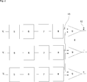
- Fig. 3 demonstrates phase shifting stage circuit blocks for brushless DC motor sensorless control scheme according to the present invention.
- the present invention proposes an electrical household appliance and particularly a refrigerator, a washing machine, a dishwasher, a drying machine or a combo drying and washing machine, which might contain an electric motor in the form of a brushless DC (BLDC) motor to fulfill various functions for instance in a washing machine, such as for instance driving a jet pump for spraying water jets into the rotary drum targeting at specific regions inside the same, at which the laundry may tend to adhere within the same, driving a discharge pump for discharging the water contained in the drum or driving a discharge pump as well as a circulation pump for circulating a refrigerant fluid.
- BLDC brushless DC
- the electrical household appliance comprises a power module in the form of a three-phase inverter driver circuit (4) driving a brushless DC motor (1) having three phases.
- High side power switches and low side power switches of the power module are typically provided with freewheeling diodes allowing reverse current to flow therethrough to be dissipated. Phase windings are thereby deenergized through respective freewheeling diodes and the stored magnetic energy in the respective phases is dissipated.
- the six step trapezoidal BLDC control method can be conventionally performed without making use of Hall sensors such that timing to commutate the drive voltages are determined by way of sensing the BEMF voltage on a not driven motor terminal. For each step (60 electrical degrees), two windings are energized and one winding is not energized. In a sensorless configuration, thanks to the back-EMF sensing principle, the commutation moments can be derived from the zero-crossings of the back-EMF. Timing to commutate the motor-drive voltages are determined by way of sensing the BEMF voltage on a not driven motor terminal.
- a microcontroller (3) conventionally detects phase voltage and bus voltage when they are equal to each other.
- the phase zero crossing can be detected at the moment when the phase voltage crosses the half DC-bus voltage.
- the respective commutation moment is then configured as being shifted in accordance with the speed of the motor.
- all terminal voltages of the motor being connected to respective input pins of the microprocessor (3), the voltage of the respective floating terminal is sampled at the end of the PWM off time. This information being compared with a minimal value, the commutation state of the motor is determined. Commutation will not be achieved at the zero-crossing point but this event is used as reference point to determine where the rotor is positioned.
- the respective commutation moment is configured as being shifted as will be delineated hereinafter.
- the brushless DC motor (1) is connected to a rotor position detecting and phase shifting circuit (2), which in turn comprises a voltage divider circuit (5) stage, a first level filter (6), a switched phase-shifting circuit (7) also acting as a second level filter, a third level filter (8) and a comparator (9).
- phase difference between current waveform of the motor at its actual speed and at the desired speed thereof is first determined and commutation is performed based on the waveform of the current at the desired speed.
- Commutation points are determined by shifting zero-crossing points back or forth by which motor speed is regulated. It is to be noted that it is possible to increase motor speed by bringing the zero-crossing points closer to one another and to decrease motor speed by taking the same apart from one another.
- phase voltages in the three phases of the motor are measured by the voltage divider circuit (5) through a reference resistor.
- the achieved voltage values are both connected to a capacitor (11) through a switching element (12) and to a waveform comparator (9) in order to perform a comparison with the previously determined zero-crossing point.
- a three-phase commutation signal (10) is thereby obtained.
- said capacitor (11) is charged so that motor speed is regulated in accordance with charging and discharging time of said capacitor (11). More precisely, phase waveform corrected in accordance with desired motor speed is obtained in accordance with charging and discharging time of said capacitor (11).
- time between zero-crossing points i.e. charging and discharging time of the capacitor (11) is increased and in the event that motor speed is desired to be increased, time between zero-crossing points (i.e. charging and discharging time) is decreased.
- the present invention proposes an electrical household appliance comprising at least one electric motor, a driver circuit capable of driving said at least one electric motor, said driver circuit comprising a converter that converts AC mains voltage to DC voltage, a driver circuit inverter stage that inverts the direct current, said driver circuit inverter stage comprising a inverter power module.
- Said electric motor is a brushless DC motor (1) and said power module comprises high side and low side power switches with freewheeling diodes.
- Said inverter power module is a six-switch three-phase inverter connected to a DC link.
- Said electrical household appliance is a refrigerator, washing machine, a dishwasher, a drying machine or a combo drying and washing machine.
- the third level filter (8) typically suppresses fluctuations occurring due to switching element (12).
- an electrical household appliance comprising at least one electric motor, a three-phase inverter driver circuit (4) capable of driving said at least one electric motor.
- Said three-phase inverter driver circuit (4) comprises a converter that converts AC mains voltage to DC voltage and a driver circuit inverter stage that inverts the direct current.
- said electric motor is a brushless DC motor (1) connected to a rotor position detecting and phase shifting circuit (2), the latter circuit comprising a switched phase-shifting circuit (7) and a comparator (9) such that phase difference between current waveform of the motor at its actual speed and at the desired speed thereof is determined and commutation is performed based on the waveform of the current at the desired speed.
- commutation points are determined by shifting zero-crossing points being determined by way of sensing back EMF voltage on a not driven motor terminal back or forth, by which motor speed is regulated.
- motor speed is increased by bringing said zero-crossing points closer to one another and decreased by taking said zero-crossing points apart from one another.
- back EMF voltage on a not driven motor terminal is sampled at the end of a PWM off time.
- said position detecting and phase shifting circuit (2) comprises a voltage divider circuit (5) stage measuring phase voltages in the three phases of the motor through a reference resistor.
- commutation moments are configured to be shifted in accordance with the speed of the motor to be adjusted in the manner that phase voltages in the three phases of the brushless DC motor (1) are connected to a capacitor (11) through a switching element (12).
- said switching element (12) controls charging and/or discharging amount of said capacitor (11).
- phase voltages in the three phases of the brushless DC motor (1) are connected to a waveform comparator (9) through said capacitor (11).
- said waveform comparator (9) compares waveforms obtained by phase-shifting.
- said capacitor (11) when said switching element (12) is in operation, said capacitor (11) is charged so that motor speed is regulated in accordance with charging and discharging time of said capacitor (11).
- charging and discharging time of the capacitor (11) is increased to decrease motor’s speed and charging and discharging time of the capacitor (11) is decreased to increase motor’s speed.
- said capacitor (11) is controlled by said switching element (12) whose base or gate is driven through PWM signals.
- said electrical household appliance is a refrigerator, a washing machine, a dishwasher, a drying machine or a combo drying and washing machine.
- a brushless DC motor (1) having a rotor position detecting and phase shifting circuit (2) is proposed
- the present invention ensures a control scheme according to which commutation points are determined by shifting zero-crossing points back or forth so that motor speed can be regulated. This is achieved thanks to a capacitor controlled by a switching element whose base or gate is driven through PWM signals so as to obtain variable speed control.
Abstract
The present invention relates to an electrical household appliance with a brushless DC motor sensorless control scheme. The present invention more particularly relates to an electrical household appliance comprising at least one electric motor, a three-phase inverter driver circuit (4) capable of driving said at least one electric motor, said three-phase inverter driver circuit (4) comprising a converter that converts AC mains voltage to DC voltage and a driver circuit inverter stage that inverts the direct current.
Description
The present invention relates to an electrical household appliance with a brushless DC motor sensorless control scheme.
It is well-known that a synchronous machine is an electrical machine with a rotating stator magnetic flux and a rotor flux locked therewith to rotate in the synchronous frequency. A brushless DC (BLDC) motor is a kind of synchronous motor that has trapezoidal back-EMF voltage shape.
It is also well-known that synchronous motors are widely used in rotary household appliances and especially in refrigerators, dishwashers and laundry treatment appliances. For instance, washing machines may have a jet pump for spraying water jets into the rotary drum targeting at specific regions inside it, at which the laundry may tend to adhere within the same, as well as a discharge pump for discharging the water contained in the drum. Likewise, a washing and/or drying machine may have a discharge pump as well as a circulation pump for circulating a refrigerant fluid.
A three-phase inverter driver circuit can typically be used to drive the BLDC motor. An inverter has six semiconductor switches with the inverter drivers collected in a single package in the form of an integrated power module (IPM). The semiconductors in the power module or inverter can be of different types such as; MOSFET, IGBT, etc.
One of the well-known six step trapezoidal BLDC control method involves positionment control of the rotor by a microcontroller. The BLDC motor is used in various applications due to its compact size and easy controllability. It is usually operated with one or more rotor-position sensors. However, the motor control can be performed without making use of Hall sensors in the manner that timing to commutate the motor-drive voltages are determined by way of sensing the BEMF voltage on a not driven motor terminal. In this case, for each step of 60 electrical degrees, two windings are energized and one winding is not energized.
Among others, one of the prior art disclosures in the technical field of the present invention can be referred to as WO2012053027, which discloses a boost DC-to-DC converter capable of changing a voltage ratio between an input voltage and an output voltage smoothly in a wide range. Two pairs of one reactor and one battery is connected by a parallel switch. The parallel switch and one pair of the reactor and the battery are short-circuited by the first parallel switch. The parallel switch and the other pair of the reactor and the battery are short-circuited by the second parallel switch. The switched reluctance motor has a transient period while a freewheeling current is flowing from a phase winding of the switched reluctance motor. In a first half of transient period, the boost DC-to-DC converter applies a boost voltage to the bridge converter.
The present invention, on the other hand, provides a control scheme according to which commutation times are determined by shifting zero-crossing points back or forth so that motor speed can be regulated. This is achieved thanks to a capacitor controlled by a switching element whose base or gate is driven through PWM signals so as to obtain variable speed control.
Primary object of the present invention is therefore to provide an electrical household appliance with a BLDC motor control scheme by which variable speed control can be performed in a sensorless control scheme.
The present invention proposes an electrical household appliance comprising an inverter power module driving a brushless DC motor, in the form of a six-switch three-phase inverter connected to a DC link. A rotor position detecting and phase shifting circuit has a switched phase-shifting circuit such that phase difference between current waveform of the motor at its actual speed and at the desired speed thereof is determined and commutation is performed based on the waveform of the current at the desired speed. Commutation points are determined by shifting zero-crossing points back and forth to control motor speed. A switching element controls charging and/or discharging amount of a capacitor such that motor speed is regulated in accordance with charging and discharging time of said capacitor. said capacitor is controlled by said switching element whose base or gate is driven through PWM signals.
Accompanying drawings are given solely for the purpose of exemplifying a household appliance having a BLDC motor and a control scheme whose advantages over prior art were outlined above and will be explained in brief hereinafter.
The drawings are not meant to delimit the scope of protection as identified in the claims nor should they be referred to alone in an effort to interpret the scope identified in said claims without recourse to the technical disclosure in the description of the present invention.
Fig. 1 demonstrates a general block diagram of the motor with control components according to the present invention. Motor phases are shown with phase voltages V1, V2 and V3.
Fig. 2 demonstrates circuit stages for brushless DC motor sensorless control scheme according to the present invention.
Fig. 3 demonstrates phase shifting stage circuit blocks for brushless DC motor sensorless control scheme according to the present invention.
The following numerals being referred to are used in the detailed description of the invention:
- Brushless DC motor
- Rotor position detecting and phase shifting circuit
- Microcontroller
- Three-phase inverter driver circuit
- Voltage divider circuit
- First filter
- Switched phase-shifting circuit
- Third level filter
- Waveform comparator
- Three-phase commutation signal
- Capacitor
- Switching element
- Trapezoidal/sinusoidal waveform
The present invention proposes an electrical household appliance and particularly a refrigerator, a washing machine, a dishwasher, a drying machine or a combo drying and washing machine, which might contain an electric motor in the form of a brushless DC (BLDC) motor to fulfill various functions for instance in a washing machine, such as for instance driving a jet pump for spraying water jets into the rotary drum targeting at specific regions inside the same, at which the laundry may tend to adhere within the same, driving a discharge pump for discharging the water contained in the drum or driving a discharge pump as well as a circulation pump for circulating a refrigerant fluid.
The electrical household appliance comprises a power module in the form of a three-phase inverter driver circuit (4) driving a brushless DC motor (1) having three phases. High side power switches and low side power switches of the power module are typically provided with freewheeling diodes allowing reverse current to flow therethrough to be dissipated. Phase windings are thereby deenergized through respective freewheeling diodes and the stored magnetic energy in the respective phases is dissipated.
The six step trapezoidal BLDC control method can be conventionally performed without making use of Hall sensors such that timing to commutate the drive voltages are determined by way of sensing the BEMF voltage on a not driven motor terminal. For each step (60 electrical degrees), two windings are energized and one winding is not energized. In a sensorless configuration, thanks to the back-EMF sensing principle, the commutation moments can be derived from the zero-crossings of the back-EMF. Timing to commutate the motor-drive voltages are determined by way of sensing the BEMF voltage on a not driven motor terminal. A microcontroller (3) conventionally detects phase voltage and bus voltage when they are equal to each other. The phase zero crossing can be detected at the moment when the phase voltage crosses the half DC-bus voltage. The respective commutation moment is then configured as being shifted in accordance with the speed of the motor. In practice, all terminal voltages of the motor being connected to respective input pins of the microprocessor (3), the voltage of the respective floating terminal is sampled at the end of the PWM off time. This information being compared with a minimal value, the commutation state of the motor is determined. Commutation will not be achieved at the zero-crossing point but this event is used as reference point to determine where the rotor is positioned.
In accordance with the present invention, the respective commutation moment is configured as being shifted as will be delineated hereinafter. To this end, the brushless DC motor (1) is connected to a rotor position detecting and phase shifting circuit (2), which in turn comprises a voltage divider circuit (5) stage, a first level filter (6), a switched phase-shifting circuit (7) also acting as a second level filter, a third level filter (8) and a comparator (9). According to the present invention, phase difference between current waveform of the motor at its actual speed and at the desired speed thereof is first determined and commutation is performed based on the waveform of the current at the desired speed. Commutation points are determined by shifting zero-crossing points back or forth by which motor speed is regulated. It is to be noted that it is possible to increase motor speed by bringing the zero-crossing points closer to one another and to decrease motor speed by taking the same apart from one another.
In accordance with the present invention, phase voltages in the three phases of the motor are measured by the voltage divider circuit (5) through a reference resistor. The achieved voltage values are both connected to a capacitor (11) through a switching element (12) and to a waveform comparator (9) in order to perform a comparison with the previously determined zero-crossing point. A three-phase commutation signal (10) is thereby obtained.
Accordingly, when said switching element (12) is in operation, said capacitor (11) is charged so that motor speed is regulated in accordance with charging and discharging time of said capacitor (11). More precisely, phase waveform corrected in accordance with desired motor speed is obtained in accordance with charging and discharging time of said capacitor (11). When it is aimed at decreasing motor’s speed, time between zero-crossing points, i.e. charging and discharging time of the capacitor (11) is increased and in the event that motor speed is desired to be increased, time between zero-crossing points (i.e. charging and discharging time) is decreased.
In a nutshell, the present invention proposes an electrical household appliance comprising at least one electric motor, a driver circuit capable of driving said at least one electric motor, said driver circuit comprising a converter that converts AC mains voltage to DC voltage, a driver circuit inverter stage that inverts the direct current, said driver circuit inverter stage comprising a inverter power module. Said electric motor is a brushless DC motor (1) and said power module comprises high side and low side power switches with freewheeling diodes. Said inverter power module is a six-switch three-phase inverter connected to a DC link. Said electrical household appliance is a refrigerator, washing machine, a dishwasher, a drying machine or a combo drying and washing machine. The third level filter (8) typically suppresses fluctuations occurring due to switching element (12).
In one embodiment of the present invention, an electrical household appliance comprising at least one electric motor, a three-phase inverter driver circuit (4) capable of driving said at least one electric motor is proposed. Said three-phase inverter driver circuit (4) comprises a converter that converts AC mains voltage to DC voltage and a driver circuit inverter stage that inverts the direct current.
In a further embodiment of the present invention, said electric motor is a brushless DC motor (1) connected to a rotor position detecting and phase shifting circuit (2), the latter circuit comprising a switched phase-shifting circuit (7) and a comparator (9) such that phase difference between current waveform of the motor at its actual speed and at the desired speed thereof is determined and commutation is performed based on the waveform of the current at the desired speed.
In a further embodiment of the present invention, commutation points are determined by shifting zero-crossing points being determined by way of sensing back EMF voltage on a not driven motor terminal back or forth, by which motor speed is regulated.
In a further embodiment of the present invention, motor speed is increased by bringing said zero-crossing points closer to one another and decreased by taking said zero-crossing points apart from one another.
In a further embodiment of the present invention, back EMF voltage on a not driven motor terminal is sampled at the end of a PWM off time.
In a further embodiment of the present invention, said position detecting and phase shifting circuit (2) comprises a voltage divider circuit (5) stage measuring phase voltages in the three phases of the motor through a reference resistor.
In a further embodiment of the present invention, commutation moments are configured to be shifted in accordance with the speed of the motor to be adjusted in the manner that phase voltages in the three phases of the brushless DC motor (1) are connected to a capacitor (11) through a switching element (12).
In a further embodiment of the present invention, said switching element (12) controls charging and/or discharging amount of said capacitor (11).
In a further embodiment of the present invention, phase voltages in the three phases of the brushless DC motor (1) are connected to a waveform comparator (9) through said capacitor (11).
In a further embodiment of the present invention, said waveform comparator (9) compares waveforms obtained by phase-shifting.
In a further embodiment of the present invention, when said switching element (12) is in operation, said capacitor (11) is charged so that motor speed is regulated in accordance with charging and discharging time of said capacitor (11).
In a further embodiment of the present invention, charging and discharging time of the capacitor (11) is increased to decrease motor’s speed and charging and discharging time of the capacitor (11) is decreased to increase motor’s speed.
In a further embodiment of the present invention, said capacitor (11) is controlled by said switching element (12) whose base or gate is driven through PWM signals.
In a further embodiment of the present invention, said electrical household appliance is a refrigerator, a washing machine, a dishwasher, a drying machine or a combo drying and washing machine.
In a further embodiment of the present invention, a brushless DC motor (1) having a rotor position detecting and phase shifting circuit (2) is proposed
Accordingly, the present invention ensures a control scheme according to which commutation points are determined by shifting zero-crossing points back or forth so that motor speed can be regulated. This is achieved thanks to a capacitor controlled by a switching element whose base or gate is driven through PWM signals so as to obtain variable speed control.
Claims (14)
- An electrical household appliance comprising at least one electric motor, a three-phase inverter driver circuit (4) capable of driving said at least one electric motor, said three-phase inverter driver circuit (4) comprising a converter that converts AC mains voltage to DC voltage and a driver circuit inverter stage that inverts the direct current, characterized in that;said electric motor is a brushless DC motor (1) connected to a rotor position detecting and phase shifting circuit (2), the latter circuit comprising a switched phase-shifting circuit (7) and a comparator (9) such that phase difference between current waveform of the motor at its actual speed and at the desired speed thereof is determined and commutation is performed based on the waveform of the current at the desired speed.
- An electrical household appliance as in Claim 1, characterized in that commutation points are determined by shifting zero-crossing points being determined by way of sensing back EMF voltage on a not driven motor terminal back or forth, by which motor speed is regulated.
- An electrical household appliance as in Claim 2, characterized in that motor speed is increased by bringing said zero-crossing points closer to one another and decreased by taking said zero-crossing points apart from one another.
- An electrical household appliance as in Claim 3, characterized in that back EMF voltage on a not driven motor terminal is sampled at the end of a PWM off time.
- An electrical household appliance as in Claim 3 or 4, characterized in that said position detecting and phase shifting circuit (2) comprises a voltage divider circuit (5) stage measuring phase voltages in the three phases of the motor through a reference resistor.
- An electrical household appliance as in Claim 3, 4 or 5, characterized in that commutation moments are configured to be shifted in accordance with the speed of the motor to be adjusted in the manner that phase voltages in the three phases of the brushless DC motor (1) are connected to a capacitor (11) through a switching element (12).
- An electrical household appliance as in Claim 6, characterized in that said switching element (12) controls charging and/or discharging amount of said capacitor (11).
- An electrical household appliance as in Claim 6 or 7, characterized in that phase voltages in the three phases of the brushless DC motor (1) are connected to a waveform comparator (9) through said capacitor (11).
- An electrical household appliance as in Claim 8, characterized in that said waveform comparator (9) compares waveforms obtained by phase-shifting.
- An electrical household appliance as in Claim 8 or 9, characterized in that when said switching element (12) is in operation, said capacitor (11) is charged so that motor speed is regulated in accordance with charging and discharging time of said capacitor (11).
- An electrical household appliance as in Claim 10, characterized in that charging and discharging time of the capacitor (11) is increased to decrease motor’s speed and charging and discharging time of the capacitor (11) is decreased to increase motor’s speed.
- An electrical household appliance as in Claim 7, characterized in that said capacitor (11) is controlled by said switching element (12) whose base or gate is driven through PWM signals.
- An electrical household appliance as in any preceding Claims, characterized in that said electrical household appliance is a refrigerator, a washing machine, a dishwasher, a drying machine or a combo drying and washing machine.
- A brushless DC motor (1) having a rotor position detecting and phase shifting circuit (2) as in Clam 1.
Priority Applications (2)
| Application Number | Priority Date | Filing Date | Title |
|---|---|---|---|
| PCT/EP2017/052312 WO2018141394A1 (en) | 2017-02-03 | 2017-02-03 | Household appliance with brushless dc motor sensorless control scheme |
| TR2018/01024A TR201801024A2 (en) | 2017-02-03 | 2018-01-24 | BRUSHLESS RIGHT CURRENT MOTOR HOUSEHOLD DEVICE WITH SENSORLESS CONTROL SCHEME |
Applications Claiming Priority (1)
| Application Number | Priority Date | Filing Date | Title |
|---|---|---|---|
| PCT/EP2017/052312 WO2018141394A1 (en) | 2017-02-03 | 2017-02-03 | Household appliance with brushless dc motor sensorless control scheme |
Publications (1)
| Publication Number | Publication Date |
|---|---|
| WO2018141394A1 true WO2018141394A1 (en) | 2018-08-09 |
Family
ID=58162505
Family Applications (1)
| Application Number | Title | Priority Date | Filing Date |
|---|---|---|---|
| PCT/EP2017/052312 WO2018141394A1 (en) | 2017-02-03 | 2017-02-03 | Household appliance with brushless dc motor sensorless control scheme |
Country Status (2)
| Country | Link |
|---|---|
| TR (1) | TR201801024A2 (en) |
| WO (1) | WO2018141394A1 (en) |
Cited By (1)
| Publication number | Priority date | Publication date | Assignee | Title |
|---|---|---|---|---|
| CN112737427A (en) * | 2021-01-15 | 2021-04-30 | 北京绿能芯创电子科技有限公司 | High-speed DC brushless motor driver |
Citations (5)
| Publication number | Priority date | Publication date | Assignee | Title |
|---|---|---|---|---|
| US20060132075A1 (en) * | 2004-12-17 | 2006-06-22 | Samsung Electronics Co., Ltd. | Startup control method of brushless DC motor |
| WO2012053027A1 (en) | 2010-10-18 | 2012-04-26 | Three Eye Co., Ltd. | Boost dc-to-dc converter and switched reluctance motor powered with the same |
| US20140167666A1 (en) * | 2012-12-18 | 2014-06-19 | William Boyd Alcorn | Systems and Methods for Reduction of Motor Jitter While Driving an Electric Motor |
| US20140176031A1 (en) * | 2012-12-21 | 2014-06-26 | Samsung Electro-Mechanics Co., Ltd. | Back electromotive force detection circuit and motor driving control apparatus using the same |
| US20140232311A1 (en) * | 2013-02-20 | 2014-08-21 | Microchip Technology Incorporated | Method and System for Determining the Position of a Synchronous Motor's Rotor |
-
2017
- 2017-02-03 WO PCT/EP2017/052312 patent/WO2018141394A1/en active Application Filing
-
2018
- 2018-01-24 TR TR2018/01024A patent/TR201801024A2/en unknown
Patent Citations (5)
| Publication number | Priority date | Publication date | Assignee | Title |
|---|---|---|---|---|
| US20060132075A1 (en) * | 2004-12-17 | 2006-06-22 | Samsung Electronics Co., Ltd. | Startup control method of brushless DC motor |
| WO2012053027A1 (en) | 2010-10-18 | 2012-04-26 | Three Eye Co., Ltd. | Boost dc-to-dc converter and switched reluctance motor powered with the same |
| US20140167666A1 (en) * | 2012-12-18 | 2014-06-19 | William Boyd Alcorn | Systems and Methods for Reduction of Motor Jitter While Driving an Electric Motor |
| US20140176031A1 (en) * | 2012-12-21 | 2014-06-26 | Samsung Electro-Mechanics Co., Ltd. | Back electromotive force detection circuit and motor driving control apparatus using the same |
| US20140232311A1 (en) * | 2013-02-20 | 2014-08-21 | Microchip Technology Incorporated | Method and System for Determining the Position of a Synchronous Motor's Rotor |
Cited By (1)
| Publication number | Priority date | Publication date | Assignee | Title |
|---|---|---|---|---|
| CN112737427A (en) * | 2021-01-15 | 2021-04-30 | 北京绿能芯创电子科技有限公司 | High-speed DC brushless motor driver |
Also Published As
| Publication number | Publication date |
|---|---|
| TR201801024A2 (en) | 2018-08-27 |
Similar Documents
| Publication | Publication Date | Title |
|---|---|---|
| Su et al. | Low-cost sensorless control of brushless DC motors with improved speed range | |
| KR100659423B1 (en) | Motor driving device | |
| WO2014135903A2 (en) | Drive circuit for a brushless motor | |
| JP2013179833A (en) | Electric compressor and household electrical appliance | |
| CN113162506A (en) | Power-off restarting method for permanent magnet synchronous motor | |
| AU2014279832A1 (en) | Method of controlling of a brushless permanent-magnet motor | |
| JP2012130111A (en) | Electric machine control apparatus | |
| US20160308476A1 (en) | Household appliance with multiple synchronous motors and control circuit thereof | |
| JP7267456B2 (en) | Sensorless motor control for power tools | |
| KR102362995B1 (en) | Motor drive device and system | |
| Lin et al. | Sensorless control for four-switch three-phase brushless DC motor drives | |
| CN102347719A (en) | Motor assembly and household appliance with same | |
| JP2012090464A (en) | Inverter control device and electric compressor and electrical equipment | |
| WO2018024571A1 (en) | Household appliance having a power module with continuous and discontinuous pwm control | |
| WO2018141394A1 (en) | Household appliance with brushless dc motor sensorless control scheme | |
| US20130307451A1 (en) | System and method for sensor-less hysteresis current control of permanent magnet synchronous generators without rotor position information | |
| CN112400274B (en) | Method for controlling brushless permanent magnet motor | |
| JP4736155B2 (en) | Inverter device | |
| JP2005057858A (en) | Motor driving device and motor driving device of dish washer | |
| GB2599669A (en) | A method of controlling a brushless permanent-magnet motor | |
| JP2010259184A (en) | Inverter controller, electric compressor, and household electrical appliance | |
| EP2965420A2 (en) | Ac/ac converter for a brushless motor | |
| WO2018001512A1 (en) | Household appliance with a power module having decreased freewheeling time duration | |
| KR101413180B1 (en) | Motor drive apparatus for washing machine and control method thereof | |
| WO2018024569A1 (en) | Household appliance having a power module with dynamically controlled switching frequency |
Legal Events
| Date | Code | Title | Description |
|---|---|---|---|
| 121 | Ep: the epo has been informed by wipo that ep was designated in this application |
Ref document number: 17707177 Country of ref document: EP Kind code of ref document: A1 |
|
| NENP | Non-entry into the national phase |
Ref country code: DE |
|
| 122 | Ep: pct application non-entry in european phase |
Ref document number: 17707177 Country of ref document: EP Kind code of ref document: A1 |