EP1542314A1 - Concept d' antenne monopole tridimensionnelle omnidirectionnelle pour des applications à bande ultra large - Google Patents
Concept d' antenne monopole tridimensionnelle omnidirectionnelle pour des applications à bande ultra large Download PDFInfo
- Publication number
- EP1542314A1 EP1542314A1 EP03028574A EP03028574A EP1542314A1 EP 1542314 A1 EP1542314 A1 EP 1542314A1 EP 03028574 A EP03028574 A EP 03028574A EP 03028574 A EP03028574 A EP 03028574A EP 1542314 A1 EP1542314 A1 EP 1542314A1
- Authority
- EP
- European Patent Office
- Prior art keywords
- monopole antenna
- radiation element
- anyone
- circular
- plane
- Prior art date
- Legal status (The legal status is an assumption and is not a legal conclusion. Google has not performed a legal analysis and makes no representation as to the accuracy of the status listed.)
- Withdrawn
Links
Images


Classifications
-
- H—ELECTRICITY
- H01—ELECTRIC ELEMENTS
- H01Q—ANTENNAS, i.e. RADIO AERIALS
- H01Q9/00—Electrically-short antennas having dimensions not more than twice the operating wavelength and consisting of conductive active radiating elements
- H01Q9/04—Resonant antennas
- H01Q9/30—Resonant antennas with feed to end of elongated active element, e.g. unipole
-
- H—ELECTRICITY
- H01—ELECTRIC ELEMENTS
- H01Q—ANTENNAS, i.e. RADIO AERIALS
- H01Q9/00—Electrically-short antennas having dimensions not more than twice the operating wavelength and consisting of conductive active radiating elements
- H01Q9/04—Resonant antennas
- H01Q9/16—Resonant antennas with feed intermediate between the extremities of the antenna, e.g. centre-fed dipole
- H01Q9/28—Conical, cylindrical, cage, strip, gauze, or like elements having an extended radiating surface; Elements comprising two conical surfaces having collinear axes and adjacent apices and fed by two-conductor transmission lines
-
- H—ELECTRICITY
- H01—ELECTRIC ELEMENTS
- H01Q—ANTENNAS, i.e. RADIO AERIALS
- H01Q23/00—Antennas with active circuits or circuit elements integrated within them or attached to them
-
- H—ELECTRICITY
- H01—ELECTRIC ELEMENTS
- H01Q—ANTENNAS, i.e. RADIO AERIALS
- H01Q9/00—Electrically-short antennas having dimensions not more than twice the operating wavelength and consisting of conductive active radiating elements
- H01Q9/04—Resonant antennas
- H01Q9/30—Resonant antennas with feed to end of elongated active element, e.g. unipole
- H01Q9/40—Element having extended radiating surface
Definitions
- the present invention generally relates to the field of microwave antennas, and more particularly, to three-dimensional designs for the radiation element of an ultra-wideband (UWB) monopole antenna with a symmetrical omni-directional radiation pattern for transmitting and/or receiving microwave signals.
- UWB ultra-wideband
- UWB generally covers a frequency range between 3.1 GHz and 10.6 GHz.
- IEEE 802.15 the disclosure of which is hereby incorporated by reference.
- the 802.15 WPANTM effort focuses on the development of Personal Area Networks or short distance wireless networks.
- These WPANs address wireless networking of portable and mobile computing devices such as PCs, Personal Digital Assistants (PDAs), peripherals, cell phones, pagers, and consumer electronics; allowing these devices to communicate and interoperate with one another.
- microwave antennas are specified according to a set of parameters including operating frequency, gain, voltage standing wave ratio (VSWR), antenna input impedance and bandwidth. If the VSWR is greater than 3, for instance, a matching network has to be placed between the transmitter and its antenna to minimize mismatch loss, although a low VSWR is not a design necessity as long as the antenna is an efficient radiator. Said design is costly and makes an automation of the matching function much slower than designs applying low-power and solid-state tuning elements.
- VSWR voltage standing wave ratio
- Ultra-wideband (UWB) technology which was originally developed for ground-penetrating radar (GPR) applications, came into use as a result of researchers' efforts for detecting and locating surface-laid and shallow-buried targets, e.g. anti-personal landmines.
- GPR ground-penetrating radar
- UWB system are e.g. used as a wireless RF interface between mobile terminals (cell phones, laptops, PDAs, wireless cameras or MP3 players) with much higher data rates than Bluetooth or IEEE 802.11.
- a UWB system can further be used as an integrated system for automotive in-car services, e.g. for downloading driving directions from a PDA or laptop for use by a GPS-based on-board navigation system, as an entertainment system or any location-based system, e.g. for downloading audio or video data for passenger entertainment.
- Ultra-wideband monopole antennas and modified monopoles are employed in a wide variety of applications today.
- mobile phones and wireless handsets are equipped with wideband and ultra-wideband monopole antennas.
- One of the most common ⁇ /4 monopole antennas is the so-called whip antenna, which can operate at a range of frequencies and is capable of dealing with most environmental conditions better than other monopole antennas.
- a monopole antenna also involves a number of drawbacks. Monopole antennas are relatively large in size and protrude from the handset case in an awkward way. The problem with a monopole antenna's obstructive and space-demanding structure complicates any efforts taken to equip a handset with several antennas to enable multi-band operation.
- IFA Inverted-F Antenna
- the IFA utilizes a modified inverted-L low profile structure, which has frequently been used for aerospace applications.
- the common IFA comprises a rectangular radiation element with an omni-directional radiation pattern and exhibits a reasonably high antenna gain.
- the bandwidth of the IFA is broad enough for mobile operation, and the antenna is also highly sensitive to both vertically and horizontally polarized radio waves, thus making the IFA ideally suited to mobile applications. Since there is an increasing demand for antennas that can be operated at multiple frequency bands, cellular phone systems nowadays operate at a number of frequency bands (e.g. 900 MHz, 1.8 GHz, and 2.0 GHz).
- An apparatus for establishing a signal coupling between a signal supply and an UWB antenna comprising a first and a second radiating element for being operated in a frequency band between 2 and 6 GHz is disclosed in WO 02/093690 A1.
- the signal supply thereby delivers a signal to the antenna at a connection locus including one edge of the first radiating element and one edge of the second radiating element.
- the apparatus further comprises a first and a second feed structure.
- Said first feed structure extends a feed distance from the signal supply to said edge of the second radiating element and divides the first radiating element into two regions in spaced relation with the first feed structure to establish a tapered separation distance between the first feed structure and the two regions.
- Said second feed structure couples the signal supply with the first radiating element. The aforementioned separation distance thereby establishes a signal transmission structure between the two regions and the first feed structure.
- the invention described in US 2002/0053994 A1 refers to a planar UWB antenna with an integrated electronic circuitry.
- the antenna comprises a first balance element which is connected to a terminal at one end.
- a second balance element is connected to another terminal at another end.
- said second balance element has a shape which mirrors the shape of the first balance element such that there is a symmetry plane where any point on the symmetry plane is equidistant to all mirror points on the first and second balance element.
- Each of the balance elements is made of an essentially conductive material.
- a triangular-shaped ground element is situated between the first balance element and the second balance element with an axis of symmetry on the symmetry plane and oriented such that the base of the triangle is towards the terminals.
- the ground element and each of the balance elements form two tapered gaps which widen and converge at the apex of the ground element as the taper extends outwardly from the terminals.
- sensitive UWB electronics can be housed within the perimeter of the ground element, thereby eliminating transmission line losses and dispersion.
- a resistive loop connected between the first and second balance element extends the low frequency response and improves the voltage standing wave ratio.
- a connection of a linear array of elements is disclosed that provides a low-frequency cutoff defined by the array size and limits its radiation pattern to one direction with a radiation angle of maximal 180 degrees in azimuth.
- an ultra-wideband antenna (frequency range between 3.1 GHz and 10.6 GHz) that fulfill the UWB standard specifications and meet the FCC requirements in terms of antenna gain, radiation pattern, polarization, frequency bandwidth, group delay, and small size.
- the present invention is basically dedicated to a number of three-dimensional designs for the radiation element of a monopole antenna with a symmetrical omni-directional radiation pattern for transmitting and/or receiving microwave signals within a predetermined bandwidth of operation, which is connectable e.g. to the analog front-end circuitry of a wireless RF transceiver.
- Said monopole antenna can be operated in the frequency range between 3.1 and 10.6 GHz. It comprises e.g.
- an air- and/or dielectric-filled cavity structure with a base plane and a radiator plane serving as a radiation element, which provides a symmetrical omni-directional radiation pattern, a metallic ground plane serving as a reflector with a relatively high surface impedance to electromagnetic waves within a limited frequency range, printed on a dielectric substrate, an antenna feeding circuitry used for electronically steering the symmetrical omni-directional radiation pattern, and a feeding line connecting the antenna feeding circuitry with the base plane of the radiation element.
- parts of the analog front-end circuitry can optionally be placed within the radiation element of the ultra-wideband monopole antenna.
- the proposed designs include a radiation element having the form of a truncated right circular cone, rotational-symmetric radiation elements with a convexly- or concavely-shaped 3D surface, respectively, a radiation element in the form of a truncated right regular pyramid with a square base plane, and radiation elements with a combined structure comprising a conical, pyramidal, convexly- or concavely-shaped first part as well as a closed cylindrical or cuboidal second part whose top plane is arranged above the congruent base plane of the first part.
- Further designs include radiation elements in the form of a radially notched cylinder or hemisphere and combined structures consisting of convexly-shaped or conical parts, respectively, stacked on top of each other.
- the monopole antenna has an overall size of less than 1 cm 3 , which makes it easy to be integrated in any wireless communication device.
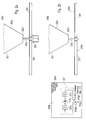
- Figs. 2a-c show the radiation element 202, which is made of copper, aluminum or any metallic components.
- the radiation element 202 can also be made of wood or plastic covered by a metallic print, its pedestal 202c, and the RF connector 206 of the ultra-wideband monopole antenna 100.
- Said pedestal 202c is attached to a dielectric substrate 205 onto which a metallic ground plane 204 is printed.
- the RF connector 206 is used for connecting the radiation element 202 with a baseband processing block 210 (in receive case) used for down-converting received microwave signals from the RF band to the baseband or with an antenna feeding circuitry 211 (in transmit case) used for electronically steering the symmetrical omni-directional radiation pattern.
- the feeding line 202b connecting the antenna feeding circuitry 211 with the base plane 202a' of the radiation element 202 is realized as a coaxial cable or as a microstrip line. Hence, any special mounting pins are not needed.
- the monopole antenna 100 has an unbalanced RF input port, e.g. as disclosed in US 2002/0053994 A1, which provides more flexibility in the implementation of consumer electronic equipment. Moreover, an unbalanced input port is more flexible when connecting the antenna to an RF module via coaxial cable. It further allows a direct connection of the metallic ground plane 204 to the ground of the antenna feeding circuitry 211 and can be used for measurement purposes in which a conventional network analyzer is sufficient, whereas in case of a balanced RF input port a differential-to-single-ended converter (a balun) is required.
- a balun differential-to-single-ended converter
- At least one part 207 of the analog front-end circuitry placed within the air-filled part of the radiation element 202 of the ultra-wideband monopole antenna 100 comprises band-select filtering means 207a for attenuating spurious out-of-band components contained in the RF signal spectrum of a received microwave signal, amplification means 207b for controlling the input power level of the wireless communication device and band-pass filtering means 207c for suppressing out-of-band frequencies in the received RF signal spectrum.
- the ultra-wideband monopole antenna is a part of an antenna terminal which is specially designed for being operated in the frequency range between 3.1 and 10.6 GHz.
- Said antenna provides a symmetrical omni-directional radiation pattern in azimuth plane with 90 degrees in elevation over the entire frequency range.
- [dB], which is defined over the magnitude of the complex-valued reflection coefficient ⁇ as the ratio (in dB) of the power incident on the antenna terminal to the power reflected from the antenna terminal, has a value of less than -10 dB in a frequency range between 3.1 GHz and 10.6 GHz, which corresponds to a voltage standing wave ratio VSWR 1 +
- a resistive load and/or additional impedance matching circuitries are used, a return loss even better than -10 dB can be achieved.
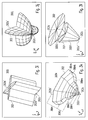
- Fig. 3a depicts a first 3D surface plot showing a first design for the radiation element 202 of the monopole antenna 100 according to a first embodiment 300a of the present invention, wherein the radiation element 202 has a rotational-symmetric form with a circular cross section and a conical structure.
- the second 3D surface plot depicted in Fig. 3b which shows a second design for the radiation element 202 of the monopole antenna 100 according to a second embodiment 300b of the present invention, comprises a first part 300b1 having a rotational-symmetric form with a circular cross section, a conical structure and a second part 300b2 having the form of a closed right circular cylinder with a circular top plane congruent to the circular base plane of the conical first part 300b1.
- the circular top plane of the cylindrical second part 300b2 is coaxially arranged above the circular base plane of the conical first part 300b1.
- 3c depicts a third 3D surface plot showing a third design for the radiation element 202 of the monopole antenna 100 according to a third embodiment 300c of the present invention, wherein the radiation element 202 has a rotational-symmetric form with a circular cross section, a conical structure and a concave 3D surface.
- the fourth 3D surface plot depicted in Fig. 3d which shows a fourth design for the radiation element 202 of the monopole antenna 100 according to a fourth embodiment 300d of the present invention, comprises a first part 300d1 having a rotational-symmetric form with a circular cross section, a conical structure, a concave 3D surface and a second part 300d2 having the form of a closed right circular cylinder with a circular top plane congruent to the circular base plane of the conical first part 300d1, wherein the circular top plane of the cylindrical second part 300d2 is coaxially arranged above the circular base plane of the concavely-shaped first part 300d1.
- Fig. 3e depicts a fifth 3D surface plot showing a fifth design for the radiation element 202 of the monopole antenna 100 according to a fifth embodiment 300e of the present invention, wherein the radiation element 202 has a rotational-symmetric form with a circular cross section, a conical structure and a convex 3D surface.
- the sixth 3D surface plot depicted in Fig. 3f which shows a sixth design for the radiation element 202 of the monopole antenna 100 according to a sixth embodiment 300f of the present invention, comprises a first part 300f1 having a rotational-symmetric form with a circular cross section, a conical structure, a convex 3D surface and a second part 300f2 having the form of a closed right circular cylinder with a circular top plane congruent to the circular base plane of the conical first part 300f1, wherein the top plane of the cylindrical second part 300f2 is coaxially arranged above the base plane of the convexly-shaped first part 300f1.
- Fig. 3g depicts a seventh 3D surface plot showing a seventh design for the radiation element 202 of the monopole antenna 100 according to a seventh embodiment 300g of the present invention, wherein the radiation element 202 has the form of a truncated right regular pyramid with a square base plane.
- the eighth 3D surface plot depicted in Fig. 3h which shows an eighth design for the radiation element 202 of the monopole antenna 100 according to an eighth embodiment 300h of the present invention, comprises a first part 300h1 in form of a truncated right square pyramid and a second part 300h2 having the form of a closed right rectangular parallelepiped (a cuboid) with a square top plane congruent to the square base plane of the pyramidal first part 300h1, wherein the square top plane of the cuboidal second part 300h2 is placed above the congruent square base plane of the pyramidal first part 300h1.
- a cuboid closed right rectangular parallelepiped
- Fig. 3i depicts a ninth 3D surface plot showing a ninth design for the radiation element 202 of the monopole antenna 100 according to a ninth embodiment 300i of the present invention, wherein the radiation element 202 has the form of a right circular cylinder with four V-shaped radial notches running in longitudinal direction, equally spaced in azimuthal direction around the circumference of the cylinder, which leads to a cross section in the form of two perpendicular elliptical stripes.
- Fig. 3j depicts a tenth 3D surface plot showing a tenth design for the radiation element 202 of the monopole antenna 100 according to a tenth embodiment 300j of the present invention, wherein the radiation element 202 has the form of a hemisphere with four V-shaped radial notches running in longitudinal direction, equally spaced in azimuth around the circumference of the hemisphere, which leads to a cross section in the form of two perpendicular elliptical stripes.
- the eleventh 3D surface plot depicted in Fig. 3k which shows an eleventh design for the radiation element 202 of the monopole antenna 100 according to an eleventh embodiment 300k of the present invention, comprises at least two parts of same or different height, each part having a rotational-symmetric form with a circular cross section, a conical structure as well as a convex 3D surface.
- Fig. 3k shows an example in which only four parts are used (300k1, 300k2, 300k3, 300k4), wherein each of the parts 300k2, 300k3, and 300k4 has a circular top plane which is congruent to the circular base plane of the parts 300k1, 300k2, and 300k3, respectively.
- Said parts 300k1, 300k2, 300k3, and 300k4 are stacked on top of each other in the order of the length of their radii.
- the circular top planes of the parts 300k2, 300k3, and 300k4 are coaxially arranged on top of the congruent circular base planes of the adjacent next smaller parts 300k1, 300k2, and 300k3, respectively.
- the twelfth 3D surface plot depicted in Fig. 31, which shows a twelfth design for the radiation element 202 of the monopole antenna 100 according to a twelfth embodiment 3001 of the present invention, comprises a first part 300l1 having the form of a truncated right circular cone and a second part having the form of a closed right circular cone with a smaller height and a bigger aperture angle, wherein the cone top of the second part 300l2 is coaxially arranged above the center of the circular base plane of the first part 300l1.
- the reactance X ( ⁇ ) can be hold to a minimum over a wide frequency range.
- the resistive part R ( ⁇ ) of the antenna input impedance Z ( ⁇ ) becomes less sensitive to changing angular frequency ⁇ or changes in the length.
- a still further embodiment of the present invention refers to an RF transceiver of a wireless communications device, wherein a monopole antenna 100 as described above is employed. Furthermore, a further monopole antenna 100' of the same type as described above can be symmetrically attached to the rear side of the metallic ground plane 204 with respect to the existing monopole antenna 100, thus forming a dipole antenna dimensioned for the Ultra-Wideband frequency range.
- the invention refers to an electronic device having a wireless interface which comprises an RF transceiver as described above.
- a wireless interface which comprises an RF transceiver as described above.
- the baseband processing block 210 of the ultra-wideband monopole Tx/Rx antenna 100 which is used for up-converting baseband signals to be transmitted from the baseband to an RF band and down-converting received microwave signals from the RF band to the baseband, re-spectively, and the antenna feeding circuitry 211 of the ultra-wideband monopole Tx/Rx antenna 100, which is used for electronically steering the radiation beam of the symmetrical omni-directional radiation pattern 202 radiation element of the ultra-wideband monopole Tx/Rx antenna 100 202a air- and/or dielectric-filled cavity resonator with a conductive surface, which serves as a radiation element 202 202a' base plane of the radiation element 202, made of a conducting material, which is connected with the baseband processing block 210 (in receive case) or the antenna feeding circuitry 211 (in transmit case), respectively 202b' radiator plane of the radiation element 202, made of a conducting material 202b feeding line connecting the antenna feeding circuitry 211 with
- Fig. 3a as well as a second part 300b2 having the form of a closed right circular cylinder with a circular top plane congruent to the circular base plane of the conical first part 300b1, wherein the circular top plane of the cylindrical second part 300b2 is coaxially arranged above the circular base plane of the conical first part 300b1 (approximated by a 3D surface plot showing a truncated right regular octagonal pyramid 300b1 with a right regular octagonal prism 300b2 whose top plane is arranged above the congruent base plane of the truncated right regular octagonal pyramid 300b1) 300b1 first part of the second 3D surface plot structure 300b, having a rotational-symmetric form with a circular cross section and a conical structure (cf.
- Fig. 3a 300b2 second part of the second 3D surface plot structure 300b with the form of a right circular cylinder, coaxially arranged above the congruent base plane of the first part 300b1 300c third 3D surface plot showing a third design of the monopole antenna 100 according to a third embodiment of the present invention, wherein the radiation element 202 has a rotational-symmetric form with a circular cross section, a conical structure and a concave surface (for simplification of the graphical representation sketched in form of three truncated right regular octagonal pyramids 300c1, 300c2, and 300c3) 300d fourth 3D surface plot showing a fourth design of the monopole antenna 100 according to a fourth embodiment of the present invention, wherein the radiation element 202 comprises a first part 300d1 having a rotational-symmetric form with a circular cross section, a conical structure and a concave surface (cf.
- a second part 300d2 having the form of a closed right circular cylinder with a circular top plane congruent to the circular base plane of the conical first part 300d1, wherein the circular top plane of the cylindrical second part 300d2 is coaxially arranged above the circular base plane of the concavely-shaped first part 300d1 (approximated by a 3D surface plot showing three truncated right regular octagonal pyramids 300d1a-c with a right regular octagonal prism 300d2 whose top plane is arranged above the congruent base plane of the biggest pyramid 300d1c) 300d1 first part of the fourth 3D surface plot structure 300d, having a rotational-symmetric form with a circular cross section, a conical structure and a concave surface (cf.
- Fig. 3c 300d2 second part of the fourth 3D surface plot structure 300d with a cylindrical form, coaxially arranged above the congruent base plane of the first part 300d1 300e fifth 3D surface plot showing a fifth design of the monopole antenna 100 according to a fifth embodiment of the present invention, wherein the radiation element 202 has a rotational-symmetric form with a circular cross section, a conical structure and a convex surface (for simplification of the graphical representation sketched in form of three truncated right regular octagonal pyramids 300e1, 300e2, and 300e3) 300f sixth 3D surface plot showing a sixth design of the monopole antenna 100 according to a sixth embodiment of the present invention, wherein the radiation element 202 comprises a first part 300f1 having a rotational-symmetric form with a circular cross section, a conical structure and a convex surface (cf.
- a second part 300f2 having the form of a closed right circular cylinder with a circular top plane congruent to the circular base plane of the conical first part 300f1, wherein the top plane of the cylindrical second part 300f2 is coaxially arranged above the base plane of the convexly-shaped first part 300f1 (approximated by a 3D surface plot showing three truncated right regular octagonal pyramids 300f1a-c with a right regular octagonal prism whose top plane is arranged above the congruent base plane of the biggest pyramid 300f1c) 300f1 first part of the sixth 3D surface plot structure 300f, having a rotational-symmetric form with a circular cross section, a conical structure and a convex surface (cf.
- Fig. 3e 300f2 second part of the sixth 3D surface plot structure 300f with a cylindrical form, coaxially arranged above the congruent base plane of the first part 300f1 300g seventh 3D surface plot showing a seventh design of the monopole antenna 100 according to a seventh embodiment of the present invention, wherein the radiation element 202 has the form of a truncated right regular pyramid with a square base plane 300h eighth 3D surface plot showing an eighth design of the monopole antenna 100 according to an eighth embodiment of the present invention, wherein the radiation element 202 comprises a first part 300h1 in form of a truncated right square pyramid (cf. Fig.
- a second part 300h2 having the form of a closed right rectangular parallelepiped (a cuboid) with a square top plane congruent to the square base plane of the pyramidal first part 300h1, wherein the square top plane of the cuboidal second part 300h2 is arranged above the congruent base plane of said first part 300h1 300h1 first part of the eighth 3D surface plot structure 300h, having the form of a truncated right square pyramid (cf. Fig.
- 300h2 second part of the eighth 3D surface plot structure 300h having the form of a right rectangular parallelepiped (cuboid) with a square base plane 202a' arranged above the congruent base plane of the first part 300h1 300i ninth 3D surface plot showing a ninth design of the monopole antenna 100 according to a ninth embodiment of the present invention, wherein the radiation element 202 has the form of a right circular cylinder with four V-shaped radial notches running in longitudinal direction, equally spaced in azimuth around the circumference of the cylinder, which leads to a cross section in the form of two perpendicularly crossing stripes, each stripe having a radially tapered thickness and rounded ends 300j tenth 3D surface plot showing a tenth design of the monopole antenna 100 according to a tenth embodiment of the present invention, wherein the radiation element 202 has the form of a hemisphere with four V-shaped radial notches running in longitudinal direction, equally spaced in azimuth around the
Landscapes
- Details Of Aerials (AREA)
- Variable-Direction Aerials And Aerial Arrays (AREA)
- Waveguide Aerials (AREA)
- Aerials With Secondary Devices (AREA)
Priority Applications (5)
| Application Number | Priority Date | Filing Date | Title |
|---|---|---|---|
| EP03028574A EP1542314A1 (fr) | 2003-12-11 | 2003-12-11 | Concept d' antenne monopole tridimensionnelle omnidirectionnelle pour des applications à bande ultra large |
| US11/007,949 US7286094B2 (en) | 2003-12-11 | 2004-12-09 | Three-dimensional omni-directional antenna designs for ultra-wideband applications |
| KR1020040104441A KR20050058229A (ko) | 2003-12-11 | 2004-12-10 | 초광대역 어플리케이션용 3차원 전방향성 안테나 설계 |
| JP2004360611A JP2005198270A (ja) | 2003-12-11 | 2004-12-13 | 超広帯域用の3次元無指向性アンテナ |
| CNB2004101007606A CN100477381C (zh) | 2003-12-11 | 2004-12-13 | 用于超宽频带应用的三维全向天线设计 |
Applications Claiming Priority (1)
| Application Number | Priority Date | Filing Date | Title |
|---|---|---|---|
| EP03028574A EP1542314A1 (fr) | 2003-12-11 | 2003-12-11 | Concept d' antenne monopole tridimensionnelle omnidirectionnelle pour des applications à bande ultra large |
Publications (1)
| Publication Number | Publication Date |
|---|---|
| EP1542314A1 true EP1542314A1 (fr) | 2005-06-15 |
Family
ID=34486192
Family Applications (1)
| Application Number | Title | Priority Date | Filing Date |
|---|---|---|---|
| EP03028574A Withdrawn EP1542314A1 (fr) | 2003-12-11 | 2003-12-11 | Concept d' antenne monopole tridimensionnelle omnidirectionnelle pour des applications à bande ultra large |
Country Status (5)
| Country | Link |
|---|---|
| US (1) | US7286094B2 (fr) |
| EP (1) | EP1542314A1 (fr) |
| JP (1) | JP2005198270A (fr) |
| KR (1) | KR20050058229A (fr) |
| CN (1) | CN100477381C (fr) |
Cited By (11)
| Publication number | Priority date | Publication date | Assignee | Title |
|---|---|---|---|---|
| WO2007048258A1 (fr) * | 2005-10-27 | 2007-05-03 | Huber+Suhner Ag | Configuration d’antenne avec antenne monopole large bande |
| WO2008118192A1 (fr) * | 2007-03-23 | 2008-10-02 | Qualcomm Incorporated | Antenne comportant des premiers et second éléments rayonnants ayant sensiblement les mêmes caractéristiques |
| WO2009029642A1 (fr) * | 2007-08-30 | 2009-03-05 | Harris Corporation | Antenne polyèdrique et procédés associés |
| WO2010070019A1 (fr) * | 2008-12-19 | 2010-06-24 | Thales | Antenne omnidirectionnelle tres large bande |
| WO2013051945A1 (fr) * | 2011-10-07 | 2013-04-11 | 3D-Radar As | Antenne de radar pénétrant |
| FR3002698A1 (fr) * | 2013-02-22 | 2014-08-29 | Onera (Off Nat Aerospatiale) | Procede et antenne monopole pour l'uniformisation du rayonnement de cette antenne disposee dans un radome. |
| DE202015001972U1 (de) | 2015-03-09 | 2016-03-10 | Sputnik24 Communication Systems GmbH | Multifunktions-Antennensystem mit RADAR-Reflektor |
| WO2017083347A1 (fr) * | 2015-11-09 | 2017-05-18 | Wiser Systems, Inc. | Antennes ultralarge bande (ulb) et enceintes associées pour lesdites antennes ulb |
| US9843101B2 (en) | 2014-01-30 | 2017-12-12 | 3D-Radar As | Antenna system for ground penetrating radar |
| CN109149079A (zh) * | 2017-06-15 | 2019-01-04 | 广州中海达定位技术有限公司 | 超宽带单极子天线 |
| US11605895B1 (en) | 2021-10-05 | 2023-03-14 | The Boeing Company | Active biconical antenna and receive array |
Families Citing this family (45)
| Publication number | Priority date | Publication date | Assignee | Title |
|---|---|---|---|---|
| JP2006186945A (ja) * | 2004-12-28 | 2006-07-13 | Toyota Motor Corp | アンテナ装置及びこれを用いた通信方法 |
| US7095374B2 (en) * | 2005-01-25 | 2006-08-22 | Lenova (Singapore) Pte. Ltd. | Low-profile embedded ultra-wideband antenna architectures for wireless devices |
| US20060176221A1 (en) * | 2005-02-04 | 2006-08-10 | Chen Zhi N | Low-profile embedded ultra-wideband antenna architectures for wireless devices |
| CA2552303A1 (fr) * | 2005-07-15 | 2007-01-15 | M/A-Com, Inc. | Dispositif d'antenne inclinable fixe |
| JP2007235395A (ja) * | 2006-02-28 | 2007-09-13 | Mitsumi Electric Co Ltd | 広帯域アンテナ装置 |
| US7443350B2 (en) * | 2006-07-07 | 2008-10-28 | International Business Machines Corporation | Embedded multi-mode antenna architectures for wireless devices |
| EP1939981B1 (fr) * | 2006-12-26 | 2016-08-03 | Samsung Electronics Co., Ltd. | Appareil d'antenne |
| US9031613B2 (en) * | 2007-12-21 | 2015-05-12 | University Of New Brunswick | Joint communication and electromagnetic optimization of a multiple-input multiple-output ultra wideband base station antenna |
| JP4281023B1 (ja) * | 2008-02-18 | 2009-06-17 | 日本電気株式会社 | ワイドバンドアンテナおよびそれを用いたウエア、持ち物 |
| JP4394732B1 (ja) * | 2008-10-17 | 2010-01-06 | 三菱電線工業株式会社 | 広帯域アンテナ |
| US8188925B2 (en) * | 2008-11-07 | 2012-05-29 | Microsoft Corporation | Bent monopole antenna with shared segments |
| CN101872887B (zh) * | 2009-04-24 | 2013-10-30 | 连展科技电子(昆山)有限公司 | 具连接装置之宽带天线 |
| US8896495B2 (en) * | 2009-07-01 | 2014-11-25 | Bae Systems Information And Electronic Systems Integration Inc. | Method for direct connection of MMIC amplifiers to balanced antenna aperture |
| CN101777704B (zh) * | 2010-02-21 | 2013-02-06 | 摩比天线技术(深圳)有限公司 | 一种室内全向天线 |
| US8345639B2 (en) | 2010-06-14 | 2013-01-01 | Raytheon Company | Broad propagation pattern antenna |
| US8674870B2 (en) * | 2011-01-19 | 2014-03-18 | Photonic Systems, Inc. | Methods and apparatus for active reflection |
| WO2012101979A1 (fr) * | 2011-01-24 | 2012-08-02 | 株式会社村田製作所 | Sonde de champ électrique |
| CN102110910B (zh) * | 2011-01-27 | 2014-10-29 | 广东通宇通讯股份有限公司 | 室内双极化全向天线 |
| WO2012144084A1 (fr) * | 2011-04-21 | 2012-10-26 | 新興産業株式會社 | Antenne composite |
| US9929462B2 (en) | 2011-06-10 | 2018-03-27 | Xizhong Long | Multiple layer dielectric panel directional antenna |
| CN103187619A (zh) * | 2013-04-01 | 2013-07-03 | 金明涛 | 椭圆振子超宽带天线 |
| CN103414015B (zh) * | 2013-08-08 | 2015-08-19 | 清华大学 | 宽带三维全向平面天线 |
| US9442034B2 (en) * | 2013-11-22 | 2016-09-13 | Ford Global Technologies, Llc | Engine knock signal transmissive element |
| US9553369B2 (en) * | 2014-02-07 | 2017-01-24 | Her Majesty The Queen In Right Of Canada, As Represented By The Minister Of National Defence | Ultra-wideband biconical antenna with excellent gain and impedance matching |
| EP3002826B1 (fr) | 2014-07-03 | 2024-04-17 | Swisscom AG | Appareil d'antenne |
| US9614273B1 (en) * | 2015-08-19 | 2017-04-04 | Sandia Corporation | Omnidirectional antenna having constant phase |
| NZ742895A (en) * | 2015-12-01 | 2019-11-29 | Isolynx Llc | Folded uwb monopole antenna for body mounted transmitter and manufacturing method |
| CN106450693B (zh) * | 2016-09-30 | 2024-02-20 | 广东通宇通讯股份有限公司 | 室内全向吸顶天线 |
| CN106654556B (zh) * | 2016-12-16 | 2019-05-14 | 电子科技大学 | 一种适用于5g通信的小型化宽频带天线 |
| CN107895840B (zh) * | 2017-11-03 | 2018-09-18 | 西安科技大学 | 一种边缘馈电的抛物面锥体超宽带天线 |
| CN107768834B (zh) * | 2017-11-06 | 2024-01-02 | 南京濠暻通讯科技有限公司 | 一种单极子标签天线 |
| CN108089158A (zh) * | 2018-01-08 | 2018-05-29 | 西安电子工程研究所 | 一种全向雷达角反射器阵列 |
| CN108254630B (zh) * | 2018-02-07 | 2023-09-12 | 西安星网天线技术有限公司 | 一种短波天线方向图和增益的测量系统及方法 |
| DE102018105837A1 (de) * | 2018-03-14 | 2019-09-19 | HELLA GmbH & Co. KGaA | Fahrzeug mit einer Einrichtung zur passiven Zugangskontrolle |
| CN108879093B (zh) * | 2018-06-27 | 2020-11-27 | 苏州浪潮智能科技有限公司 | 一种应用于存储系统上的无线仲裁微带天线 |
| US10833399B1 (en) * | 2018-08-30 | 2020-11-10 | Bae Systems Information And Electronic Systems Integration Inc. | Embedded wide band monocone antenna |
| CN112751169B (zh) * | 2019-10-31 | 2023-11-21 | 深圳富泰宏精密工业有限公司 | 天线结构及具有该天线结构的无线通信装置 |
| CN113708065B (zh) * | 2020-05-21 | 2023-03-10 | 华为技术有限公司 | 一种准全向天线及信号收发设备 |
| KR102211234B1 (ko) * | 2020-06-02 | 2021-02-03 | (주)브로드텍인터내셔널 | 무선 통신 기기용 안테나의 정재파비 측정 제어 장치 및 그 방법 |
| CN111987429B (zh) * | 2020-08-03 | 2022-10-21 | 中国舰船研究设计中心 | 一种超宽带全向辐射充气式天线 |
| US11342679B1 (en) * | 2020-09-30 | 2022-05-24 | Bae Systems Information And Electronic Systems Integration Inc. | Low profile monocone antenna |
| US11469519B1 (en) * | 2021-06-07 | 2022-10-11 | The Florida International University Board Of Trustees | Antenna arrays with three-dimensional radiating elements |
| CN114256607B (zh) * | 2021-12-22 | 2022-12-13 | 电子科技大学 | 一种高功率超宽带电磁辐射天线 |
| CN114050405B (zh) * | 2021-12-31 | 2022-04-26 | 陕西海积信息科技有限公司 | 线阵车载天线和设备 |
| WO2023211906A1 (fr) * | 2022-04-29 | 2023-11-02 | KYOCERA AVX Components (San Diego), Inc. | Ensemble antenne à bande ultra-large |
Citations (4)
| Publication number | Priority date | Publication date | Assignee | Title |
|---|---|---|---|---|
| US2454766A (en) * | 1943-04-24 | 1948-11-30 | Standard Telephones Cables Ltd | Broad band antenna |
| DE1466400A1 (de) * | 1965-12-23 | 1970-04-16 | Siemens Ag | Breitbandstrahler kleinen Schlankheitsgrades mit Hochpasscharakter |
| EP0766343A2 (fr) * | 1995-09-27 | 1997-04-02 | Ntt Mobile Communications Network Inc. | Antenne à large bande avec une source semi-circulaire |
| US20020053994A1 (en) * | 1999-05-03 | 2002-05-09 | Xtremespectrum, Inc | Planar ultra wide band antenna with integrated electronics |
Family Cites Families (6)
| Publication number | Priority date | Publication date | Assignee | Title |
|---|---|---|---|---|
| US3829863A (en) * | 1973-03-12 | 1974-08-13 | Gen Instrument Corp | Polarizing feed apparatus for biconical antennas |
| US4851859A (en) * | 1988-05-06 | 1989-07-25 | Purdue Research Foundation | Tunable discone antenna |
| US5929819A (en) * | 1996-12-17 | 1999-07-27 | Hughes Electronics Corporation | Flat antenna for satellite communication |
| US5990845A (en) * | 1997-07-02 | 1999-11-23 | Tci International | Broadband fan cone direction finding antenna and array |
| US6346920B2 (en) * | 1999-07-16 | 2002-02-12 | Eugene D. Sharp | Broadband fan cone direction finding antenna and array |
| US6646605B2 (en) * | 2000-10-12 | 2003-11-11 | E-Tenna Corporation | Tunable reduced weight artificial dielectric antennas |
-
2003
- 2003-12-11 EP EP03028574A patent/EP1542314A1/fr not_active Withdrawn
-
2004
- 2004-12-09 US US11/007,949 patent/US7286094B2/en not_active Expired - Fee Related
- 2004-12-10 KR KR1020040104441A patent/KR20050058229A/ko not_active Application Discontinuation
- 2004-12-13 JP JP2004360611A patent/JP2005198270A/ja active Pending
- 2004-12-13 CN CNB2004101007606A patent/CN100477381C/zh not_active Expired - Fee Related
Patent Citations (4)
| Publication number | Priority date | Publication date | Assignee | Title |
|---|---|---|---|---|
| US2454766A (en) * | 1943-04-24 | 1948-11-30 | Standard Telephones Cables Ltd | Broad band antenna |
| DE1466400A1 (de) * | 1965-12-23 | 1970-04-16 | Siemens Ag | Breitbandstrahler kleinen Schlankheitsgrades mit Hochpasscharakter |
| EP0766343A2 (fr) * | 1995-09-27 | 1997-04-02 | Ntt Mobile Communications Network Inc. | Antenne à large bande avec une source semi-circulaire |
| US20020053994A1 (en) * | 1999-05-03 | 2002-05-09 | Xtremespectrum, Inc | Planar ultra wide band antenna with integrated electronics |
Cited By (19)
| Publication number | Priority date | Publication date | Assignee | Title |
|---|---|---|---|---|
| WO2007048258A1 (fr) * | 2005-10-27 | 2007-05-03 | Huber+Suhner Ag | Configuration d’antenne avec antenne monopole large bande |
| WO2008118192A1 (fr) * | 2007-03-23 | 2008-10-02 | Qualcomm Incorporated | Antenne comportant des premiers et second éléments rayonnants ayant sensiblement les mêmes caractéristiques |
| WO2009029642A1 (fr) * | 2007-08-30 | 2009-03-05 | Harris Corporation | Antenne polyèdrique et procédés associés |
| US7808441B2 (en) | 2007-08-30 | 2010-10-05 | Harris Corporation | Polyhedral antenna and associated methods |
| WO2010070019A1 (fr) * | 2008-12-19 | 2010-06-24 | Thales | Antenne omnidirectionnelle tres large bande |
| FR2940531A1 (fr) * | 2008-12-19 | 2010-06-25 | Thales Sa | Antenne omnidirectionnelle tres large bande |
| WO2013051945A1 (fr) * | 2011-10-07 | 2013-04-11 | 3D-Radar As | Antenne de radar pénétrant |
| US9478872B2 (en) | 2011-10-07 | 2016-10-25 | 3D-Radar As | Ground penetrating radar antenna |
| US9281555B2 (en) | 2013-02-22 | 2016-03-08 | Airbus Operations (S.A.S.) | Method and monopole antenna for making uniform the radiation of said antenna, when disposed inside a radome |
| FR3002698A1 (fr) * | 2013-02-22 | 2014-08-29 | Onera (Off Nat Aerospatiale) | Procede et antenne monopole pour l'uniformisation du rayonnement de cette antenne disposee dans un radome. |
| US9843101B2 (en) | 2014-01-30 | 2017-12-12 | 3D-Radar As | Antenna system for ground penetrating radar |
| DE202015001972U1 (de) | 2015-03-09 | 2016-03-10 | Sputnik24 Communication Systems GmbH | Multifunktions-Antennensystem mit RADAR-Reflektor |
| WO2016141912A1 (fr) | 2015-03-09 | 2016-09-15 | Sputnik24 Communication Systems GmbH | Système d'antenne multifonction présentant un réflecteur pour radar |
| US10677911B2 (en) | 2015-03-09 | 2020-06-09 | Sputnik24 Communication Systems GmbH | Multi-function antenna system with radar reflector |
| WO2017083347A1 (fr) * | 2015-11-09 | 2017-05-18 | Wiser Systems, Inc. | Antennes ultralarge bande (ulb) et enceintes associées pour lesdites antennes ulb |
| US11233327B2 (en) | 2015-11-09 | 2022-01-25 | Wiser Systems, Inc. | Ultra-wideband (UWB) antennas and related enclosures for the UWB antennas |
| CN109149079A (zh) * | 2017-06-15 | 2019-01-04 | 广州中海达定位技术有限公司 | 超宽带单极子天线 |
| US11605895B1 (en) | 2021-10-05 | 2023-03-14 | The Boeing Company | Active biconical antenna and receive array |
| EP4164060A1 (fr) * | 2021-10-05 | 2023-04-12 | The Boeing Company | Antenne biconique active et réseau de réception |
Also Published As
| Publication number | Publication date |
|---|---|
| US20050156804A1 (en) | 2005-07-21 |
| US7286094B2 (en) | 2007-10-23 |
| JP2005198270A (ja) | 2005-07-21 |
| CN1627563A (zh) | 2005-06-15 |
| KR20050058229A (ko) | 2005-06-16 |
| CN100477381C (zh) | 2009-04-08 |
Similar Documents
| Publication | Publication Date | Title |
|---|---|---|
| US7286094B2 (en) | Three-dimensional omni-directional antenna designs for ultra-wideband applications | |
| US7545339B2 (en) | Planar antenna apparatus for ultra wide band applications | |
| US9024831B2 (en) | Miniaturized ultra-wideband multifunction antenna via multi-mode traveling-waves (TW) | |
| JP4677445B2 (ja) | 無線アプリケーション用低背型スマートアンテナおよびその関連方法 | |
| US8259014B2 (en) | Multi-loop antenna structure and hand-held electronic device using the same | |
| US7821470B2 (en) | Antenna arrangement | |
| CN110364824B (zh) | 双频天线模块 | |
| CN102110899A (zh) | 一种集成滤波器的超宽带天线 | |
| US6535166B1 (en) | Capacitively coupled plated antenna | |
| US20030103008A1 (en) | In-building low profile antenna | |
| US20240275072A1 (en) | Dual-frequency band dual-circularly polarized antenna and antenna system | |
| CN101800357A (zh) | 双频印刷式单极天线 | |
| US7541985B2 (en) | Multi-broad band antenna and electronic device thereof | |
| US7193580B2 (en) | Antenna device | |
| US10374311B2 (en) | Antenna for a portable communication device | |
| US9431710B2 (en) | Printed wide band monopole antenna module | |
| CN101246994B (zh) | 多频段宽频天线及应用其的手持式电子装置 | |
| CN110165395B (zh) | 一种小型化紧凑型三频带天线 | |
| CN110085982B (zh) | 超宽带双极化天线及其制作方法 | |
| US20110148735A1 (en) | Dual-band antenna | |
| US20130099978A1 (en) | Internal printed antenna | |
| Rao | Antenna configurations for software defined radio and cognitive radio communication architecture | |
| WO2023001031A1 (fr) | Unité d'antenne, émetteur-récepteur sans fil et dispositif électronique | |
| EP4432470A1 (fr) | Système d'antenne pour cycle d'ordinateur de bicyclette électronique intelligente | |
| US20240097347A1 (en) | Antenna structure |
Legal Events
| Date | Code | Title | Description |
|---|---|---|---|
| PUAI | Public reference made under article 153(3) epc to a published international application that has entered the european phase |
Free format text: ORIGINAL CODE: 0009012 |
|
| AK | Designated contracting states |
Kind code of ref document: A1 Designated state(s): AT BE BG CH CY CZ DE DK EE ES FI FR GB GR HU IE IT LI LU MC NL PT RO SE SI SK TR |
|
| AX | Request for extension of the european patent |
Extension state: AL LT LV MK |
|
| RAP1 | Party data changed (applicant data changed or rights of an application transferred) |
Owner name: SONY DEUTSCHLAND GMBH |
|
| 17P | Request for examination filed |
Effective date: 20051020 |
|
| RAP1 | Party data changed (applicant data changed or rights of an application transferred) |
Owner name: SONY DEUTSCHLAND GMBH |
|
| RAP1 | Party data changed (applicant data changed or rights of an application transferred) |
Owner name: SONY DEUTSCHLAND GMBH |
|
| AKX | Designation fees paid |
Designated state(s): AT BE BG CH CY CZ DE DK EE ES FI FR GB GR HU IE IT LI LU MC NL PT RO SE SI SK TR |
|
| 17Q | First examination report despatched |
Effective date: 20070531 |
|
| STAA | Information on the status of an ep patent application or granted ep patent |
Free format text: STATUS: THE APPLICATION IS DEEMED TO BE WITHDRAWN |
|
| 18D | Application deemed to be withdrawn |
Effective date: 20100701 |