EP1542305A1 - System und Verfahren zur Entfernung von Wasserstoff aus Brennstoffzellen-Abgasen - Google Patents
System und Verfahren zur Entfernung von Wasserstoff aus Brennstoffzellen-Abgasen Download PDFInfo
- Publication number
- EP1542305A1 EP1542305A1 EP04029073A EP04029073A EP1542305A1 EP 1542305 A1 EP1542305 A1 EP 1542305A1 EP 04029073 A EP04029073 A EP 04029073A EP 04029073 A EP04029073 A EP 04029073A EP 1542305 A1 EP1542305 A1 EP 1542305A1
- Authority
- EP
- European Patent Office
- Prior art keywords
- burner
- gas
- fuel cell
- catalytic
- temperature
- Prior art date
- Legal status (The legal status is an assumption and is not a legal conclusion. Google has not performed a legal analysis and makes no representation as to the accuracy of the status listed.)
- Granted
Links
- 239000001257 hydrogen Substances 0.000 title claims abstract description 129
- 229910052739 hydrogen Inorganic materials 0.000 title claims abstract description 129
- 239000000446 fuel Substances 0.000 title claims abstract description 118
- UFHFLCQGNIYNRP-UHFFFAOYSA-N Hydrogen Chemical compound [H][H] UFHFLCQGNIYNRP-UHFFFAOYSA-N 0.000 title claims abstract description 106
- 238000000034 method Methods 0.000 title claims description 24
- 239000002912 waste gas Substances 0.000 title abstract description 5
- 239000007789 gas Substances 0.000 claims abstract description 202
- 230000003197 catalytic effect Effects 0.000 claims abstract description 118
- XLYOFNOQVPJJNP-UHFFFAOYSA-N water Substances O XLYOFNOQVPJJNP-UHFFFAOYSA-N 0.000 claims abstract description 59
- 229910001868 water Inorganic materials 0.000 claims abstract description 59
- 238000006243 chemical reaction Methods 0.000 claims description 39
- 150000002431 hydrogen Chemical class 0.000 claims description 22
- QVGXLLKOCUKJST-UHFFFAOYSA-N atomic oxygen Chemical compound [O] QVGXLLKOCUKJST-UHFFFAOYSA-N 0.000 claims description 15
- 239000001301 oxygen Substances 0.000 claims description 15
- 229910052760 oxygen Inorganic materials 0.000 claims description 15
- 230000001276 controlling effect Effects 0.000 claims description 12
- 239000002737 fuel gas Substances 0.000 claims description 11
- 238000010926 purge Methods 0.000 claims description 10
- 230000001105 regulatory effect Effects 0.000 claims description 10
- 241001156002 Anthonomus pomorum Species 0.000 claims description 9
- OKKJLVBELUTLKV-UHFFFAOYSA-N Methanol Chemical compound OC OKKJLVBELUTLKV-UHFFFAOYSA-N 0.000 claims description 9
- 239000000463 material Substances 0.000 claims description 9
- 238000010438 heat treatment Methods 0.000 claims description 8
- VNWKTOKETHGBQD-UHFFFAOYSA-N methane Chemical compound C VNWKTOKETHGBQD-UHFFFAOYSA-N 0.000 claims description 8
- 238000007254 oxidation reaction Methods 0.000 claims description 8
- 239000011148 porous material Substances 0.000 claims description 8
- 230000003647 oxidation Effects 0.000 claims description 7
- ATUOYWHBWRKTHZ-UHFFFAOYSA-N Propane Chemical compound CCC ATUOYWHBWRKTHZ-UHFFFAOYSA-N 0.000 claims description 6
- 238000012544 monitoring process Methods 0.000 claims description 6
- 230000009467 reduction Effects 0.000 claims description 6
- 239000007787 solid Substances 0.000 claims description 6
- 230000001419 dependent effect Effects 0.000 claims description 4
- 239000007788 liquid Substances 0.000 claims description 4
- 239000001273 butane Substances 0.000 claims description 3
- 230000008859 change Effects 0.000 claims description 3
- IJDNQMDRQITEOD-UHFFFAOYSA-N n-butane Chemical compound CCCC IJDNQMDRQITEOD-UHFFFAOYSA-N 0.000 claims description 3
- OFBQJSOFQDEBGM-UHFFFAOYSA-N n-pentane Natural products CCCCC OFBQJSOFQDEBGM-UHFFFAOYSA-N 0.000 claims description 3
- 239000001294 propane Substances 0.000 claims description 3
- 239000000443 aerosol Substances 0.000 claims description 2
- 239000003502 gasoline Substances 0.000 claims description 2
- 239000004215 Carbon black (E152) Substances 0.000 claims 3
- 229930195733 hydrocarbon Natural products 0.000 claims 3
- 150000002430 hydrocarbons Chemical class 0.000 claims 3
- 230000000977 initiatory effect Effects 0.000 claims 2
- 238000000889 atomisation Methods 0.000 claims 1
- 238000002485 combustion reaction Methods 0.000 claims 1
- 238000001816 cooling Methods 0.000 description 15
- IJGRMHOSHXDMSA-UHFFFAOYSA-N Atomic nitrogen Chemical compound N#N IJGRMHOSHXDMSA-UHFFFAOYSA-N 0.000 description 6
- 239000003054 catalyst Substances 0.000 description 6
- 239000000203 mixture Substances 0.000 description 6
- BASFCYQUMIYNBI-UHFFFAOYSA-N platinum Chemical compound [Pt] BASFCYQUMIYNBI-UHFFFAOYSA-N 0.000 description 6
- 239000012528 membrane Substances 0.000 description 5
- 239000002360 explosive Substances 0.000 description 4
- 230000001590 oxidative effect Effects 0.000 description 4
- 239000005518 polymer electrolyte Substances 0.000 description 4
- 238000001704 evaporation Methods 0.000 description 3
- 230000008020 evaporation Effects 0.000 description 3
- 238000004880 explosion Methods 0.000 description 3
- 238000011010 flushing procedure Methods 0.000 description 3
- 239000011261 inert gas Substances 0.000 description 3
- 238000002156 mixing Methods 0.000 description 3
- 229910052757 nitrogen Inorganic materials 0.000 description 3
- 229910052697 platinum Inorganic materials 0.000 description 3
- 230000002123 temporal effect Effects 0.000 description 3
- XKRFYHLGVUSROY-UHFFFAOYSA-N Argon Chemical compound [Ar] XKRFYHLGVUSROY-UHFFFAOYSA-N 0.000 description 2
- CURLTUGMZLYLDI-UHFFFAOYSA-N Carbon dioxide Chemical compound O=C=O CURLTUGMZLYLDI-UHFFFAOYSA-N 0.000 description 2
- 239000000919 ceramic Substances 0.000 description 2
- 230000000694 effects Effects 0.000 description 2
- 238000009434 installation Methods 0.000 description 2
- 229910052751 metal Inorganic materials 0.000 description 2
- 239000002184 metal Substances 0.000 description 2
- 230000035484 reaction time Effects 0.000 description 2
- 239000000126 substance Substances 0.000 description 2
- 229910018072 Al 2 O 3 Inorganic materials 0.000 description 1
- UGFAIRIUMAVXCW-UHFFFAOYSA-N Carbon monoxide Chemical compound [O+]#[C-] UGFAIRIUMAVXCW-UHFFFAOYSA-N 0.000 description 1
- OTMSDBZUPAUEDD-UHFFFAOYSA-N Ethane Chemical compound CC OTMSDBZUPAUEDD-UHFFFAOYSA-N 0.000 description 1
- 230000004913 activation Effects 0.000 description 1
- 229910052786 argon Inorganic materials 0.000 description 1
- 230000015572 biosynthetic process Effects 0.000 description 1
- 230000000903 blocking effect Effects 0.000 description 1
- 239000001569 carbon dioxide Substances 0.000 description 1
- 229910002092 carbon dioxide Inorganic materials 0.000 description 1
- 239000012876 carrier material Substances 0.000 description 1
- 239000000567 combustion gas Substances 0.000 description 1
- 239000000498 cooling water Substances 0.000 description 1
- 229910052878 cordierite Inorganic materials 0.000 description 1
- 238000013461 design Methods 0.000 description 1
- 238000011161 development Methods 0.000 description 1
- 230000018109 developmental process Effects 0.000 description 1
- JSKIRARMQDRGJZ-UHFFFAOYSA-N dimagnesium dioxido-bis[(1-oxido-3-oxo-2,4,6,8,9-pentaoxa-1,3-disila-5,7-dialuminabicyclo[3.3.1]nonan-7-yl)oxy]silane Chemical compound [Mg++].[Mg++].[O-][Si]([O-])(O[Al]1O[Al]2O[Si](=O)O[Si]([O-])(O1)O2)O[Al]1O[Al]2O[Si](=O)O[Si]([O-])(O1)O2 JSKIRARMQDRGJZ-UHFFFAOYSA-N 0.000 description 1
- 238000007599 discharging Methods 0.000 description 1
- 238000006056 electrooxidation reaction Methods 0.000 description 1
- 238000002474 experimental method Methods 0.000 description 1
- 239000003546 flue gas Substances 0.000 description 1
- 239000006260 foam Substances 0.000 description 1
- 125000004435 hydrogen atom Chemical group [H]* 0.000 description 1
- 238000002347 injection Methods 0.000 description 1
- 239000007924 injection Substances 0.000 description 1
- VUZPPFZMUPKLLV-UHFFFAOYSA-N methane;hydrate Chemical compound C.O VUZPPFZMUPKLLV-UHFFFAOYSA-N 0.000 description 1
- 230000004048 modification Effects 0.000 description 1
- 238000012986 modification Methods 0.000 description 1
- 239000002105 nanoparticle Substances 0.000 description 1
- 239000003345 natural gas Substances 0.000 description 1
- 238000005457 optimization Methods 0.000 description 1
- 239000007800 oxidant agent Substances 0.000 description 1
- 230000008569 process Effects 0.000 description 1
- 238000000746 purification Methods 0.000 description 1
- 238000002407 reforming Methods 0.000 description 1
- 230000004044 response Effects 0.000 description 1
- 230000002441 reversible effect Effects 0.000 description 1
- 238000005507 spraying Methods 0.000 description 1
- 238000012360 testing method Methods 0.000 description 1
- 230000007306 turnover Effects 0.000 description 1
Images


Classifications
-
- H—ELECTRICITY
- H01—ELECTRIC ELEMENTS
- H01M—PROCESSES OR MEANS, e.g. BATTERIES, FOR THE DIRECT CONVERSION OF CHEMICAL ENERGY INTO ELECTRICAL ENERGY
- H01M8/00—Fuel cells; Manufacture thereof
- H01M8/06—Combination of fuel cells with means for production of reactants or for treatment of residues
- H01M8/0662—Treatment of gaseous reactants or gaseous residues, e.g. cleaning
-
- H—ELECTRICITY
- H01—ELECTRIC ELEMENTS
- H01M—PROCESSES OR MEANS, e.g. BATTERIES, FOR THE DIRECT CONVERSION OF CHEMICAL ENERGY INTO ELECTRICAL ENERGY
- H01M8/00—Fuel cells; Manufacture thereof
- H01M8/04—Auxiliary arrangements, e.g. for control of pressure or for circulation of fluids
- H01M8/04007—Auxiliary arrangements, e.g. for control of pressure or for circulation of fluids related to heat exchange
-
- H—ELECTRICITY
- H01—ELECTRIC ELEMENTS
- H01M—PROCESSES OR MEANS, e.g. BATTERIES, FOR THE DIRECT CONVERSION OF CHEMICAL ENERGY INTO ELECTRICAL ENERGY
- H01M8/00—Fuel cells; Manufacture thereof
- H01M8/06—Combination of fuel cells with means for production of reactants or for treatment of residues
- H01M8/0606—Combination of fuel cells with means for production of reactants or for treatment of residues with means for production of gaseous reactants
- H01M8/0612—Combination of fuel cells with means for production of reactants or for treatment of residues with means for production of gaseous reactants from carbon-containing material
-
- H—ELECTRICITY
- H01—ELECTRIC ELEMENTS
- H01M—PROCESSES OR MEANS, e.g. BATTERIES, FOR THE DIRECT CONVERSION OF CHEMICAL ENERGY INTO ELECTRICAL ENERGY
- H01M8/00—Fuel cells; Manufacture thereof
- H01M8/24—Grouping of fuel cells, e.g. stacking of fuel cells
- H01M8/2465—Details of groupings of fuel cells
- H01M8/247—Arrangements for tightening a stack, for accommodation of a stack in a tank or for assembling different tanks
- H01M8/2475—Enclosures, casings or containers of fuel cell stacks
-
- H—ELECTRICITY
- H01—ELECTRIC ELEMENTS
- H01M—PROCESSES OR MEANS, e.g. BATTERIES, FOR THE DIRECT CONVERSION OF CHEMICAL ENERGY INTO ELECTRICAL ENERGY
- H01M2250/00—Fuel cells for particular applications; Specific features of fuel cell system
- H01M2250/20—Fuel cells in motive systems, e.g. vehicle, ship, plane
-
- Y—GENERAL TAGGING OF NEW TECHNOLOGICAL DEVELOPMENTS; GENERAL TAGGING OF CROSS-SECTIONAL TECHNOLOGIES SPANNING OVER SEVERAL SECTIONS OF THE IPC; TECHNICAL SUBJECTS COVERED BY FORMER USPC CROSS-REFERENCE ART COLLECTIONS [XRACs] AND DIGESTS
- Y02—TECHNOLOGIES OR APPLICATIONS FOR MITIGATION OR ADAPTATION AGAINST CLIMATE CHANGE
- Y02E—REDUCTION OF GREENHOUSE GAS [GHG] EMISSIONS, RELATED TO ENERGY GENERATION, TRANSMISSION OR DISTRIBUTION
- Y02E60/00—Enabling technologies; Technologies with a potential or indirect contribution to GHG emissions mitigation
- Y02E60/30—Hydrogen technology
- Y02E60/50—Fuel cells
-
- Y—GENERAL TAGGING OF NEW TECHNOLOGICAL DEVELOPMENTS; GENERAL TAGGING OF CROSS-SECTIONAL TECHNOLOGIES SPANNING OVER SEVERAL SECTIONS OF THE IPC; TECHNICAL SUBJECTS COVERED BY FORMER USPC CROSS-REFERENCE ART COLLECTIONS [XRACs] AND DIGESTS
- Y02—TECHNOLOGIES OR APPLICATIONS FOR MITIGATION OR ADAPTATION AGAINST CLIMATE CHANGE
- Y02T—CLIMATE CHANGE MITIGATION TECHNOLOGIES RELATED TO TRANSPORTATION
- Y02T90/00—Enabling technologies or technologies with a potential or indirect contribution to GHG emissions mitigation
- Y02T90/40—Application of hydrogen technology to transportation, e.g. using fuel cells
Definitions
- the invention relates to a fuel cell system with catalytic burner for the treatment of combustion gas-containing exhaust gases and a method for operating the plant.
- Fuel cells provide electrical power through electrochemical oxidation.
- the oxidizing agent is usually oxygen, which is supplied in the form of air is hydrogen, and the actual fuel is hydrogen, either directly supplied or in the system e.g. obtained by splitting natural gas becomes. Due to the flammability and the explosion tendency of the Fuels, especially hydrogen, it is desirable to release them to avoid the environment.
- Fuels especially hydrogen, it is desirable to release them to avoid the environment.
- closed Rooms should be no exhaust air with a hydrogen concentration of more than 40% of the lower explosive limit (corresponding to 1.6% by volume of hydrogen) be delivered to the environment. Also for outdoor systems it is safer if no hydrogen emissions occur.
- Catalytic burners are known in the art. You are capable of hydrogen and other fuel gases such as e.g. Methane, ethane, propane, butane, methanol to convert inert materials. Hydrogen can with the help of atmospheric oxygen be oxidized to water. If a catalytic burner flue gas a fuel cell system and oxygen or an oxygen containing Gas supplied as air, the hydrogen contained in the exhaust gas should be too Water are oxidized and no longer pose a threat.
- fuel gases such as e.g. Methane, ethane, propane, butane, methanol
- Hydrogen can with the help of atmospheric oxygen be oxidized to water. If a catalytic burner flue gas a fuel cell system and oxygen or an oxygen containing Gas supplied as air, the hydrogen contained in the exhaust gas should be too Water are oxidized and no longer pose a threat.
- the system can be designed so that the complete conversion sets optimal temperature.
- the amount of hydrogen fed in varies greatly over time subjected, e.g. due to the interval rinsing of the anode compartments in dead-end operation, or by varying the fuel cell performance.
- a particular problem is the startup phase of the system. At startup In the plant, the catalytic burner is still cold, and there is little implementation instead of hydrogen, i. there is too much hydrogen in it the environment released.
- the temperature in the catalytic burner must not be too high either become. Too high a temperature can in the worst case for ignition and cause explosive reaction of the hydrogen / air mixture in the burner. In addition, very hot burner exhaust gases are generated, which is a potential Pose a risk to operating personnel.
- Object of the present invention is therefore a fuel cell system with a catalytic burner that provides reduced exhaust gas when operating Hydrogen content generated.
- the object of the present invention is, in particular, a fuel cell system to provide with catalytic burner suitable for operation in enclosed spaces is suitable.
- Object of the present invention is further, a fuel cell system with catalytic burner, in which the formation of temperature peaks is avoided in the catalytic burner.
- Object of the present invention is also a fuel cell system with catalytic burner to provide the temperature reduced Generated exhaust.
- the fuel cell system according to the invention is efficient and compact and very suitable for applications where weight and space requirements is one Play a role, in particular for use in motor vehicles.
- the attachment has a fuel cell system with at least one fuel cell, typically using polymer electrolyte membrane fuel cells become.
- the invention is also applicable to any other fuel cell type, operated with hydrogen or generated by reforming hydrogen becomes, suitable.
- the fuel cell system exists from a stack with a plurality of fuel cells or from several Stacking each with a plurality of fuel cells, preferably polymer electrolyte membrane fuel cells.
- the fuel cells are supplied with hydrogen and oxygen, for example in the form of gas streams, the anode regions and the cathode regions Supplying hydrogen or oxygen and unused hydrogen or remove oxygen again.
- This "open" system is usually at Cathode fuel gas, for which air is typically used, used.
- the anode fuel gas can be supplied in this way, preferably However, here the so-called “dead-end” operation is selected, i. e. Becomes hydrogen fed to the anodes of the fuel cell and consumed. Collect it In the anode area unwanted products such as water and fuel gas contained foreign gases or through the membrane into the Ariode Symposium diffusing gases. These must be removed regularly, which done by rinsing.
- the "dead end" is opened and for a short time a purge gas has passed through the anode compartments.
- the purge gas can be a separate be inert gas, such as nitrogen, but usually used directly Anodenbrenngas, ie hydrogen, for rinsing. Typical intervals are one Flushing of about 0.5 s duration after every 20 to 30 s dead-end operation. at The purging bursts fresh fuel leaving the fuel cells. With Reformergas powered fuel cells are not in dead-end operation operated because the hydrogen produced in the reformer to many other gases such Contains nitrogen, carbon dioxide and water.
- the hydrogen leaving the fuel cell system by means of a downstream of the fuel cell system catalytic Brenners removed at least to a non-critical amount.
- a non-critical amount is a hydrogen concentration of at most 40%, preferably not more than 20%, considered the lower explosion limit (LEL).
- the catalytic burner is any conventional catalytic burner, for example, with platinum as the catalyst metal on a ceramic carrier material.
- the burner can be a tubular reactor with monolithic, platinum-coated Catalyst support or a reactor with a catalyst bed be.
- the type of catalytic burner is not limited, and also other materials and shapes are usable.
- the anode exhaust gas from the fuel cell system is supplied via a feed path as a first burner feed gas is fed into the catalytic burner.
- Oxygen or an oxygen-containing gas usually air in practice, is fed into the burner as a second burner feed gas.
- a certain Temperature Is the temperature too low to be available in the Reaction time, i. the gas residence time in the burner, a complete implementation of the hydrogen or, in other words, is the residence time in the burner too low to a given at the burner temperature to allow complete conversion of the hydrogen, this contains the burner leaving exhaust still too much residual hydrogen.
- the burner temperature by means of temperature sensor determined and depending on the determined temperature the Gas residence time in the burner adjusted so that sufficient hydrogen conversion he follows.
- “Sufficient” in this context means that the Hydrogen concentration at most 40%, preferably at most 20%, especially preferably not more than 10%, which is LEL.
- the setting of the gas residence time is most appropriate by appropriate regulation of the Burner with air supplying blower. A reduction in air intake increases the gas residence time in the burner and reduces the cooling by the Air flow, so increases both the available for the reaction Time and, due to the increase in temperature, the reaction rate.
- the catalytic Burner cold; Depending on the location of the plant, for example, it can be at room temperature or have a much lower temperature.
- the reaction rate of the reaction of the hydrogen is corresponding low.
- exhaust gas must be available in quantities be oxidized, as they are also during operation with a hot burner attack.
- the burner temperature fast enough to a value that fits the particular system design and the respective operating conditions sufficient hydrogen oxidation guaranteed.
- the present invention Invention several variants ready, individually or in combination can be applied.
- the oxidation air flow is chosen so small that he can just oxidise the resulting hydrogen, but hardly with the air Heat is discharged from the burner.
- the setting of the airflow can, for example, a regulation of the air blower power depending take place from the determined burner temperature.
- the fuel cells become dead-end hydrogen operated, i. it change phases in which no anode exhaust gas enters the burner, with rinsing phases in which relatively large quantities Hydrogen must be implemented.
- the air flow can be interrupted or at least reduced, so that no heat is discharged from the burner.
- the interruption or Reduction of airflow can be achieved by blocking or Control in Zuliteweg for the second burner feed gas or by a Redirection of the air flow done.
- To divert the air flow is a fixed set or provided in its amount variable bypass, through the entire air flow or part of the air flow past the burner directly into the exhaust pipe of the system is introduced. The full or partial Diverting the air flow through the bypass brings with it the effect that due to the missing or reduced air flow in the burner, the heat emission is minimized from the burner.
- the exhaust diluted and thus the hydrogen concentration be degraded in it. This is via a switchable if necessary Line further additional air fed into the exhaust.
- the diversion of the second burner feed gas, i. of air or another Oxygen-containing gas through the bypass can alternatively only in the Phases of dead-end operation of fuel cells are used or also be used during the rinsing phases, the burner only the supply stoichiometrically required amount of air and the remaining air at Burner passing directly into the exhaust of the system.
- the "cold start" be improved by the burner is heated supportively. to supporting heating is before or during commissioning of the plant a small amount of another burner feed gas intermittently or continuously metered into the burner.
- the air flow for the Reaction required amount of oxygen preferably a stoichiometric Amount of oxygen, provided.
- the amount of this third burner feed gas should be such that they are at least almost even in the cold burner completely reacted and heated to the required temperature.
- additional burner feed gas is hydrogen in question, which has one of the fuel cell system is fed independent feeder, but also all other fuels exothermic in the catalytic burner with air react and form an inert product are suitable in principle. Examples are Methane, propane, butane, etc., as available in reformate systems, In addition, liquid fuels such as gasoline, methanol, etc.
- external pre or additional heaters for example be realized electrically or in the form of a burner, and in which the catalytic burner is heated directly or via an air preheating.
- external heating requires a higher apparatus Effort and are therefore less favored.
- the setting of the required burner temperature, especially in the Starting phase of the system is thus achieved according to the invention by monitoring and optimizing the temperature of the catalytic burner by temperature-dependent temporal and / or quantitative variation of the supply of second burner feed gas and / or third burner feed gas to the catalytic converter Burner, if necessary in combination with monitoring of the hydrogen content of the burner exhaust gas to be released into the environment and optimization the temperature of the catalytic burner when exceeding the permissible Hydrogen content.
- One way of feeding the media first burner feed gas, second Brennerspeisegas and third burner feed gas according to the requirements is to vary by means of temperature sensor in the catalytic burner and if necessary by means of hydrogen sensor in the burner exhaust gas in conjunction with facilities for controlling the supply amounts of the media in the supply paths and devices for the control thereof as a function of the determined burner temperature and optionally from the determined hydrogen content.
- the catalytic burner is present or when commissioning the system immediately on the for a sufficient hydrogen conversion required minimum temperature brought by temporal and / or quantitative variation of the delivery of second and / or third Burner feed gas as a function of the determined burner temperature, particularly preferably by varying the supply of second burner feed gas. If necessary, additional air is supplied to the burner exhaust gas, to dilute the exhaust gas.
- the burner temperature required for each system and optionally air admixing with the burner exhaust during the Start-up phase must be determined by preliminary tests. After reaching The minimum temperature of the burner will increase the temperature through time and / or quantitative variation of second and / or third burner feed gas further increased to the optimum value.
- a hydrogen sensor in the Burner exhaust path is only the protection to exceed the permissible hydrogen content in the burner exhaust gas shut off the system.
- a combined Regulation of the temporal and / or quantitative supply of second and / or third burner feed gas as a function of the burner temperature and the hydrogen content of the burner exhaust gas is usually the Regulator for the supply of second and third burner feed gas in dependence controlled by the determined burner temperature. Reached the However, hydrogen content in the exhaust gas has a certain value, e.g. 10% LEL, the regulators are switched by one with the hydrogen sensor in the burner exhaust path coupled control device driven to increase the burner temperature initiate.
- the above variants of the operation of the fuel cell plant in the Starting phase can each be by itself or in combinations of two or more the variants are used.
- Burner temperature While in the start-up phase of the system problems due to too low Burner temperature exist occurs during operation of the plant rather the reverse case, i.
- the temperature in the burner may be undesirable high levels may increase and, in particular, local overshoots the desired temperature come.
- a high burner temperature has in turn a high exhaust gas temperature, resulting in hazards can.
- the temperature of the burner is monitored and regulated.
- the flow of the oxidizing gas increases and thereby the heat removal can be accelerated.
- the disadvantage of this is that higher fan powers are required and large quantities of hot exhaust gases are produced. Therefore, the preferred is the scheme the burner temperature by supplying a controlled amount of water the catalytic burner.
- product water When operating fuel cells, there is always a certain amount of product water on, which is liquid and / or in the form of an aerosol.
- the bulk of the Product water is in the cathode exhaust gas, but also in the rest of the exhaust gas
- the fuel cell may contain water. It is desirable this Water evaporates to expel liquid water with the exhaust gas to avoid.
- product water For cooling the burner by means of product water be the product water-containing exhaust gases of the fuel cell, or at least the exhaust gases containing the main part of the product water
- Fuel cells introduced into the catalytic burner, and the water evaporated. Alternatively or additionally, water from a separate reservoir be metered into the burner.
- Efficient cooling is ensured by an even distribution of water favored over the cross-sectional area of the burner.
- This can be done by that the water is introduced into a gas feed and a porous one Body, such as a porous ceramic foam body or a Fill of a porous material, is installed in the gas supply.
- the water can also be injected through nozzles in the burner, where it is finely distributed. The big surface, passing through the passage accelerated by porous material or by spraying the evaporation and thereby improves the cooling.
- the water When used for cooling water from a separate reservoir is, the water is preferably introduced with the oxidizing gas in the burner.
- the porous body or nozzles for creating a large surface of the water are then in the oxidizing gas supply, preferably in close proximity to the Brenner.
- Product water can also be introduced on the way via the oxidizing gas supply or directly with the fuel cell exhaust stream. In this case are located the porous body or the nozzles in the feed of the fuel cell exhaust gas to the burner.
- the variants for cooling the catalytic burner can be used alone or in Combination can be applied. Also a combination with the invention quick heating of the burner is possible.
- the temperature of the burner exhaust gas is monitored and regulated.
- the cooling of hot burner exhaust gases takes place by means of supply and evaporation of water (product water and / or separate water) as above for cooling described the burner, the water but the burner exhaust gas stream is supplied.
- the feeder can for example by direct Injection takes place via nozzles or via an air supply such as the one before mentioned bypass or an additional way to air supply. In the Water supply via a Heilzu 1500weg this is preferred with a porous body equipped for better distribution of water.
- the cooling of the burner and the cooling of the burner exhaust gas can depend on be combined by the operating state of the burner. Prefers They are with the inventive rapid heating of the burner in the Start-up phase combined.
- the burner exhaust path is behind the burner a solid or a solid bed arranged to the increase thermal inertia of the system. Suitable for this are temperature-resistant Materials with high heat capacity. While flushing the Fuel cells, when the maximum exhaust gas temperature is reached flows the hot exhaust gas through the material, which heats up and the exhaust gas Deprives energy, so cool it. After rinsing, when the catalytic Burner and the material in the exhaust path are only traversed by air, Both burner and the material cool down again, the exhaust gas is now heated slightly. At the next rinse the cooled Material then absorb again enthalpy.
- the different variants can used alone or in combination of two or more.
- the temperature in the catalytic burner and / or in the To regulate burner exhaust gas consists in the installation of a heat exchanger in the Burner and / or in the exhaust path of the burner.
- a heat exchanger allows to cool the burner or the exhaust gas and / or usable To gain heat.
- the release of heat enthalpy over the entire Expansion of the burner by dividing the feed points of a burner feed gas, preferably the hydrogen can be varied. It is the catalytic burner as divided into several reaction zones, where only one of the burner feed gases, preferably the air, all the reaction zones successively while metering in the other burner feed gas, preferably the hydrogen, at different points of the burner he follows. This results in a better over the entire catalyst of the burner distributed reaction, while the released enthalpy at the respective reaction site is significantly lower due to the lower hydrogen concentration. A maximum of the reaction density at the entrance of the burner is avoided.
- the hydrogen-rich fuel cell exhaust gas at a single Place fed and passed through the entire burner while the reaction air is metered in stages in several reaction zones.
- this variant is less advantageous since most of the released Heat is discharged via the exhaust air and thus at the feed point Hydrogen-rich fuel cell exhaust gas, due to the low Gas flow rates, may not be sufficient cooling.
- the Control of the temperature distribution can be done alone or in combination carried out with one or more of the aforementioned modes.
- the exhaust gas from the anode area of the Fuel cell system in the catalytic burner it is sufficient only the exhaust gas from the anode area of the Fuel cell system in the catalytic burner to remove hydrogen to treat.
- all potentially hydrogen-containing are preferred Gas streams, particularly preferably gas streams, the other combustible Gases could contain, by reaction in the catalytic burner of hydrogen freed.
- gases are in addition to the anode exhaust gas in particular the Cathode exhaust, which in the case of a leak in a polymer electrolyte membrane Hydrogen may contain, as well as from a containment, which the Fuel cell stack or the entire system preferably from the environment encapsulates, extracted air, which in case of a leak in the piping system or the fuel cell stacks may be contaminated with hydrogen.
- Fig. 1 shows the result of an experiment in which a catalytic burner was subjected to increasing temperatures with air and hydrogen.
- the burner consisted of a cordierite burner monolith (an Al 2 O 3 modification) whose surface was occupied by platinum nanoparticles.
- the burner had 900 square channels per square inch, which corresponds to about 140 channels per cm 2 .
- the cylindrical monolith had a diameter of about 100 mm and a length of about 100 mm.
- the monolith was installed in a metal tube and was flowed through by a defined air flow, the hydrogen was metered in replica of the rinsing process in a fuel cell system for a short time.
- the air flow was constant 17 Nm 3 / h.
- Hydrogen was fed in at intervals every 20 seconds, corresponding to a fuel cell purge frequency of one purge per 20 seconds, and each in an amount of about 0.9 liters.
- the temperature of the exhaust gas and its hydrogen content were measured. Since the thermocouple used had a response time T 90 (time in which 90% of a sudden change in temperature is detected) of about 10 s, the measured temperatures can only be regarded as mean values. The temperature peaks occurring immediately after rinsing should be considerably higher.
- the hydrogen content of the exhaust gas of the catalytic burner is given as a percentage of the LEL (lower explosion limit). 100% LEL corresponding to 4% by volume hydrogen in air. The concentrations are maximum values as measured shortly after rinsing in the burner exhaust gas. Between the individual purging bursts, the hydrogen content in the burner exhaust gas drops to zero.
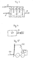
- Fig. 2 shows an exemplary embodiment of an inventive Fuel cell system 1.
- the system has a fuel cell system 2, consisting of a fuel cell stack with a plurality of polymer electrolyte membrane fuel cells, and a catalytic burner 3. Of the catalytic burner 3 is fed with anode exhaust gas from the fuel cell system 2 supplied to it via the feed path 4 and air supplied to it is supplied via the Zunaturalweg 5.
- a mixing chamber 3 'are the Gases premixed.
- the fuel cell system 2 is either in dead-end operation operated with hydrogen, it via the Zuliteweg 4 "from a Hydrogen supply (not shown) receives, or in the flow-through operation with hydrogen, which it receives from the reformer 25, and with air, through the fuel cell stack flows (not shown).
- the catalytic burner 3 can be fed via a Zunaturalweg 6 with a controller 12 additional hydrogen be and a Zunaturalweg 7 with a controller 13 Reformerspeisegas be supplied.
- the Heilzu Georgiaweg 5 has a controller 10 and is equipped with a bypass 17 with regulator 17 ', through which the air at Burner can be fed directly into the Brennerabgasweg 16.
- the Regulators regulate the flow of media in the respective feed paths or lock the inflow. Via a feed 11, the fuel cell system 2, if necessary, be purged with inert gas.
- the catalytic burner 3 When commissioning the system, the catalytic burner 3 is cold, for example in a vehicle parked outdoors in the winter. Oxidized in this state the catalytic burner hardly hydrogen and is almost useless.
- One Hydrogen sensor 26 in Brennerabgasweg 16 determines an impermissibly high Hydrogen concentration in the burner exhaust, and the system would be for safety reasons be switched off. To avoid this, according to the invention Measures taken, the temperature in the catalytic Burner 3 very quickly increase to a value of efficient oxidation of hydrogen allowed.
- the temperature in the catalytic burner is determined by means of a temperature sensor 9 monitored.
- the temperature sensor 9 is coupled to a control device, which falls below the minimum temperature of the catalytic Brenners the controller 12 or 13 controls to the burner additionally hydrogen or supply reformer feed gas and thereby heat him. Furthermore the air supply to the burner by controlling the controller 10th and / or reduced by bypassing the bypass 17.
- Fuel gas (hydrogen, reformer feed gas) and air must be sized that full implementation is guaranteed.
- the temperature sensor 9 monitors the temperature in the catalytic burner. Will she pass through the exothermic reaction is too high, water from a reservoir 18th or product water from the operation of the fuel cells for cooling in the Burners fed.
- the feed is done by controlling a controller 14 'in Wasserzu 1500weg 8 or by controlling a regulator 14 in the product water supply path 8 ".
- a porous Material 24 is provided, through which the water passes.
- a temperature sensor 15 for monitoring the temperature of the gas released to the environment. Achieve the Temperature of the exhaust gas is an impermissibly high value, is one with the Temperature sensor 15 coupled control device, the supply of water introduced into the burner exhaust gas.
- the burner exhaust path 16 has a separate Heilzu 1500weg 19, via the additional air may be fed into the burner exhaust path 16 as needed can. Additional air is fed in if the exhaust gas temperature is too high or if the hydrogen content of the exhaust gas is too high. Then the regulator 19 'of the coupled to the temperature sensor 15 control device or from the controller coupled to the hydrogen sensor 26 controlled and opened.
- the hydrogen sensor 26 is provided with means for introducing a Reduction of the hydrogen content of the burner exhaust by increasing coupled to the burner temperature. Exceeds the hydrogen content in Burner exhaust gas a predetermined value, this device controls the controller 12 or 13, and the burner is additionally hydrogen or reformer feed gas supplied and heated the burner thereby. In addition, the Air supply to the burner by controlling the controller 10 or by diverting reduced via the bypass 17.
- the quantities of heating gas (hydrogen, reformer feed gas) and air must be such that a complete Implementation is guaranteed.
- Fig. 3 shows how the temperature of the catalytic burner by varying the Supply point of the first burner feed gas can be influenced.
- the first Brennerspeisegas is anode exhaust, via a Zustockedweg 4 with branches 40, 41, 42, 43 and 44 distributed over the entire burner 3 supplied becomes.
- the second burner feed gas, air is supplied via a single feed path 5 fed into the catalytic burner and passed through the entire burner. This results in the burner reaction areas 30, 31, 32, 33 and 34, in which only a small amount of hydrogen is converted, but all the air is available for cooling. This causes a better one Temperature distribution in the catalytic burner.
- Fig. 4 shows a fuel cell system according to the invention, in which all Gases that may contain hydrogen or another combustible gas, are passed through the catalytic burner 3.
- the entire fuel cell system with all lines and ancillary equipment such as. Reformer surrounded by a container 27.
- a feed path 29 leads all the container 27 leaving the gases before their release in the environment through a catalytic burner 3.
- Fig. 5 shows a forklift 50 with inventive fuel cell system 1.
- the fuel cell system 1 serves both the drive of the forklift as well as the operation of its lifting device 51.
- the present invention allows the catalytic burner to be quickly reduced to a for a sufficient hydrogen conversion required minimum temperature To bring the temperature distribution in the burner to regulate an optimal To maintain burner temperature, the hydrogen content of the environment Discharging gas to a sufficiently low value to keep and the Temperature of the gas to be released into the environment also low hold.
- the corresponding embodiments of the present invention have each independently inventive character. To be favoured however, two or more of the embodiments according to the invention with each other combined, for example, the rapid heating of the burner in the Start-up phase of the system with one or more of the other embodiments.
Landscapes
- Life Sciences & Earth Sciences (AREA)
- Engineering & Computer Science (AREA)
- Manufacturing & Machinery (AREA)
- Sustainable Development (AREA)
- Sustainable Energy (AREA)
- Chemical & Material Sciences (AREA)
- Chemical Kinetics & Catalysis (AREA)
- Electrochemistry (AREA)
- General Chemical & Material Sciences (AREA)
- Fuel Cell (AREA)
Abstract
Description
Claims (40)
- Verfahren zur Behandlung von Abgas eines Brennstoffzellen-Systems (2), insbesondere eines Kraftfahrzeug-Brennstoffzellen-Systems, bei dem unumgesetzter Wasserstoff durch katalytische Oxidation aus dem Abgas entfernt wird, indemmindestens ein Teil des Abgases aus dem Brennstoffzellen-System als ein erstes Brennerspeisegas einem katalytischen Brenner (3)zugeführt wird,ein Sauerstoff enthaltendes Gas als ein zweites Brennerspeisegas dem katalytischen Brenner zugeführt wird,gewünschtenfalls ein Brenngas enthaltendes drittes Speisegas und/oder Wasser dem katalytischen Brenner zugeführt wird,in dem ersten Brennerspeisegas enthaltener Wasserstoff in dem katalytischen Brenner unter Erzeugung eines Brennerabgases katalytisch oxidiert wird,der Wasserstoffgehalt und/oder die Temperatur des Brennerabgases überwacht und bei Abweichung von einem vorgegebenen Wert gewünschtenfalls geregelt wird, und/oderdie Temperatur des katalytischen Brenners überwacht und dergestalt geregelt wird, dass ein gewünschter Temperaturbereich erzielt wird, wobeidie Regelung der Temperatur des katalytischen Brenners durch temperaturabhängige Variation der Zuführung mindestens eines der Medien erstes Brennerspeisegas, zweites Brennerspeisegas, drittes Brennerspeisegas und Wasser zu dem katalytischen Brenner erfolgt.
- Verfahren nach Anspruch 1, bei dem der Wasserstoffgehalt des Brennerabgases durch Änderung der Temperatur des katalytischen Brenners verringert wird.
- Verfahren nach Anspruch 1 oder 2, bei dem der Wasserstoffgehalt des Brennerabgases durch Einspeisen von zweitem Brennerspeisegas direkt in das Brennerabgas verringert wird.
- Verfahren nach einem der Ansprüche 1 bis 3, bei dem die Temperatur des in die Umgebung zu entlassenden Gases gesenkt wird, indem zweites Brennerspeisegas und/oder Wasser direkt in das Brennerabgas eingespeist wird.
- Verfahren nach einem der Ansprüche 1 bis 4, bei dem die Temperatur des in die Umgebung zu entlassenden Gases gesenkt wird, indem das Brennerabgas durch einen Festkörper oder eine Festkörperschüttung mit hoher Wärmekapazität geführt wird.
- Verfahren nach einem der Ansprüche 1 bis 5, bei dem dem katalytischen Brenner (3) als erstes Brennerspeisegas Anodenabgas und/oder als zweites Brennerspeisegas Luft zugeführt wird.
- Verfahren nach einem der Ansprüche 1 bis 6, bei dem die Regelung der Temperatur des katalytischen Brenners durch Variation der Zuführmenge und/oder der Zuführzeit und/oder der Zuführstelle des ersten Brennerspeisegases und/oder des zweiten Brennerspeisegases erfolgt.
- Verfahren nach einem der Ansprüche 1 bis 7, bei dem das Brennstoffzellen-System (2) intervallweise gespült wird, und bei dem die Regelung der Temperatur des katalytischen Brenners (3) und die Verringerung des Wasserstoffgehalts des Brennerabgases dadurch erfolgt, dass die Zuführung des zweiten Brennerspeisegases zu dem katalytischen Brenner zwischen den einzelnen Spülstößen verringert oder unterbrochen wird.
- Verfahren nach einem der Ansprüche 1 bis 8, bei dem die Regelung der Temperatur des katalytischen Brenners (3) dadurch erfolgt, dass bei zu tiefer Brennertemperatur mindestens ein Teil des zweiten Brennerspeisegases an dem Brenner vorbeigeführt und dem Brennerabgas zugeführt wird.
- Verfahren nach Anspruch 9, bei dem der Volumenstrom pro Zeiteinheit des an dem katalytischen Brenner (3) vorbeigeführten zweiten Brennerspeisegases geregelt werden kann.
- Verfahren nach einem der Ansprüche 1 bis 10, bei dem die Regelung der Temperatur des katalytischen Brenners (3) dadurch erfolgt, dass dem Brenner bis zum Erreichen der gewünschten Temperatur ein Brenngas enthaltendes drittes Speisegas zugeführt wird.
- Verfahren nach einem der Ansprüche 1 bis 11, bei dem die Regelung der Temperatur des katalytischen Brenners (3) zum raschen Aufheizen des katalytischen Brenners vor und/oder während der Startphase des Systems durchgeführt wird, insbesondere um den Wassserstoffgehalt des Brennerabgases zu verringern.
- Verfahren nach einem der Ansprüche 1 bis 12, bei dem das dritte Brennerspeisegas Wasserstoff, Methan, Propan, Butan, Benzin oder Methanol ist.
- Verfahren nach einem der Ansprüche 1 bis 13, bei dem die Menge an Brenngas im dritten Brennerspeisegas so bemessen wird, dass im katalytischen Brenner eine vollständige Verbrennung erfolgt.
- Verfahren nach einem der Ansprüche 1 bis 14, bei dem die Regelung der Temperatur des katalytischen Brenners (3) dadurch erfolgt, dass bei zu hoher Brennertemperatur dem katalytischen Brenner Produktwasser aus dem Brennstoffzellen-System (2) und/oder externes Wasser zugeführt wird.
- Verfahren nach einem der Ansprüche 1 bis 15, bei dem das Wasser als Flüssigkeit oder als Aerosol zugeführt wird.
- Verfahren nach einem der Ansprüche 1 bis 15, bei dem die Zuführung des Wassers über eine Gaszuführung und einen porösen Körper oder eine Schüttung aus porösem Material in der Gaszuführung oder durch Zerstäuben erfolgt.
- Verfahren nach einem der Ansprüche 1 bis 17, bei dem zur Erzielung einer gleichmäßigen Temperaturverteilung im katalytischen Brenner das erste Brennerspeisegas über die Ausdehnung des Brenners verteilt in verschiedenen Reaktionszonen (30, 31, 32, 33, 34) zugeführt wird und das zweite Brennerspeisegas durch den gesamten Brenner geführt wird.
- Verfahren nach einem der Ansprüche 1 bis 18, bei dem alle Gase, die im Zusammenhang mit dem Brennstoffzellen-System anfallen, vor ihrer Entlassung in die Umwelt in dem katalytischen Brenner von eventuell vorhandenem Brenngas gereinigt werden.
- Brennstoffzellen-Anlage (1), insbesondere für ein Kraftfahrzeug, aufweisendein Brennstoffzellen-System (2) mit mindesten einer Brennstoffzelle,einen katalytischen Brenner (3),einen Zuführweg (4) für ein erstes Brennerspeisegas in Form von Brennstoffzellen-Abgas zu dem katalytischen Brenner,einen Zuführweg (5) für ein Sauerstoff enthaltendes zweites Brennerspeisegas zu dem katalytischen Brenner,gewünschtenfalls einen Zuführweg (6, 7) für ein Brenngas enthaltendes drittes Brennerspeisegas zu dem katalytischen Brenner,gewünschtenfalls einen Zuführweg (8, 8') für Wasser zu dem katalytischen Brenner,einen Sensor (9) zum Überwachen der Temperatur des katalytischen Brenners, und/odereinen Sensor zum Überwachen des Wasserstoffgehalts (26) und/oder der Temperatur (15) des Brennerabgases,eine Steuereinrichtung zum Einleiten einer Änderung des Wasserstoffgehalts und/oder der Temperatur des Brennerabgases, undeine Regel-Einrichtung (10, 12, 13, 14, 14') zum Variieren der Zuführung mindestens eines der Medien erstes Brennerspeisegas, zweites Brennerspeisegas, drittes Brennerspeisegas und Wasser zu dem katalytischen Brenner in Abhängigkeit von der Temperatur des katalytischen Brenners.
- Brennstoffzellen-Anlage (1) nach Anspruch 20, aufweisendeine Steuer/Regel-Einrichtung (10) zum Freigeben der Zuführung von zweitem Brennerspeisegas zu dem katalytischen Brenner, wenn das Brennstoffzellen-System mit Wasserstoff oder einem anderen Spülgas gespült wird, und zum Verringern oder Unterbrechen der Zuführung des zweiten Brennerspeisegases zu dem katalytischen Brenner, wenn ein Spülvorgang beendet ist.
- Brennstoffzellen-Anlage (1) nach Anspruch 20 oder 21,bei der die Steuereinrichtung zum Einleiten einer Verringerung des Wasserstoffgehalts des Brennerabgases eine Einrichtung zum Ansteuern der Regel-Einrichtung (10, 12, 13) zum Variieren der Zuführung des zweiten Brennerspeisegases und/oder des dritten Brennerspeisegases ist.
- Brennstoffzellen-Anlage (1) nach einem der Ansprüche 20 bis 22, aufweisendeinen Bypass-Weg (17) zum Zuführen von zweitem Brennerspeisegas unter Umgehung des katalytischen Brenners (3) direkt in einen Brennerabgasweg (16), undeine Regel-Einrichtung (17') zum Regeln der dem Brennerabgasweg (16) zugeführten Menge an zweitem Brennerspeisegas in Abhängigkeit vom Wasserstoffgehalt des Brennerabgases.
- Brennstoffzellen-Anlage (1) nach einem der Ansprüche 20 bis 23, aufweisendeinen Zuführweg (19) zum Einspeisen von Luft in den Brennerabgasweg (16),eine Regel-Einrichtung (19') zum Regeln der über den Zuführweg (19) in den Brennerabgasweg (16) eingespeisten Luftmenge in Abhängigkeit vom Wasserstoffgehalt des Brennerabgases.
- Brennstoffzellen-Anlage (1) nach einem der Ansprüche 20 bis 24, aufweisendeinen Zuführweg (8') für Wasser in den Brennerabgasweg (16), undeine Regel-Einrichtung (28') zum Regeln der dem Brennerabgasweg (16) zugeführten Menge Wasser in Abhängigkeit von der Temperatur des Brennerabgases.
- Brennstoffzellen-Anlage (1) nach einem der Ansprüche 20 bis 25, aufweisendeinen Zuführweg (8"') für Produktwasser aus dem Brennstoffzellensystem (2) in den Brennerabgasweg (16), undeine Regel-Einrichtung (28"') zum Regeln der dem Brennerabgasweg (16) zugeführten Menge an Produktwasser in Abhängigkeit von der Temperatur des Brennerabgases.
- Brennstoffzellen-Anlage (1) nach einem der Ansprüche 20 bis 26, aufweisendeinen Zuführweg (19) zum Einspeisen von Luft in den Brennerabgasweg (16),eine Regel-Einrichtung (19') zum Regeln der über den Zuführweg (19) in den Brennerabgasweg (16) eingespeisten Luftmenge in Abhängigkeit von der Temperatur des Brennerabgases.
- Brennstoffzellen-Anlage (1) nach einem der Ansprüche 20 bis 27, bei der die Steuereinrichtung zum Einleiten einer Verringerung der Temperatur des Brennerabgases eine Einrichtung zum Ansteuern der Regel-Einrichtung (19', 28', 28"') zum Regeln der in den Brennerabgasweg (16) eingespeisten Luftmenge und/oder Wassermenge und/oder Produktwassermenge ist.
- Brennstoffzellen-Anlage (1) nach einem der Ansprüche 20 bis 28, aufweisend
einen Festkörper (23) oder eine Festkörperschüttung mit hoher Wärmekapazität oder einen Wärmetauscher im Brennerabgasweg (16). - Brennstoffzellen-Anlage (1) nach einem der Ansprüche 20 bis 29, aufweisendeinen Zuführweg (6) zum Zuführen von Wasserstoff zu dem katalytischen Brenner, undeine Regel-Einrichtung (12) zum Regeln der dem katalytischen Brenner zugeführten Menge Wasserstoff in Abhängigkeit von der Temperatur des katalytischen Brenners und/oder dem Wasserstoffgehalt des Brennerabgases.
- Brennstoffzellen-Anlage (1) nach einem der Ansprüche 20 bis 30, aufweisendeinen Reformer (25) zum Erzeugen von Wasserstoff aus Kohlenwasserstoff-Brennstoffen,einen Zuführweg (7) zum Zuführen von Kohlenwasserstoff-Brennstoffen zu dem katalytischen Brenner (3), undeine Regel-Einrichtung (13) zum Regeln der dem katalytischen Brenner zugeführten Menge an Kohlenwasserstoff-Brennstoffen in Abhängigkeit von der Temperatur des katalytischen Brenners und/oder dem Wasserstoffgehalt des Brennerabgases.
- Brennstoffzellen-Anlage (1) nach einem der Ansprüche 20 bis 31, aufweisendeinen Zuführweg (8) für Wasser zu dem katalytischen Brenner (3), undeine Regel-Einrichtung (14') zum Regeln der dem katalytischen Brenner zugeführten Menge Wasser in Abhängigkeit von der Brennertemperatur.
- Brennstoffzellen-Anlage (1) nach einem der Ansprüche 20 bis 32, aufweisendeinen Zuführweg (8") für Produktwasser aus dem Brennstoffzellen-System (2) zu dem katalytischen Brenner (3), undeine Regel-Einrichtung (14) zum Regeln der dem katalytischen Brenner zugeführten Menge Produktwasser in Abhängigkeit von der Brennertemperatur.
- Brennstoffzellen-Anlage (1) nach einem der Ansprüche 20 bis 33, aufweisendeinen porösen Körper oder eine Schüttung aus porösem Material (24) in einem Gaszuführweg zu dem katalytischen Brenner (3), durch den oder durch die eingespeistes Wasser vor dem Eintritt in den katalytischen Brenner (3) hindurch tritt.
- Brennstoffzellen-Anlage (1) nach einem der Ansprüche 20 bis 34, aufweisendeinen porösen Körper oder eine Schüttung aus porösem Material (22) in einem Gaszuführweg zu dem Brennerabgasweg (16), durch den oder durch die eingespeistes Wasser vor dem Eintritt in den Brennerabgasweg (16) hindurch tritt, oder einen porösen Körper oder eine Schüttung aus porösem Material in dem Brennerabgasweg (16).
- Brennstoffzellen-Anlage (1) nach einem der Ansprüche 20 bis 35, aufweisendeinen katalytischen Brenner (3), der in zwei oder mehr Reaktionszonen (30, 31, 32, 33, 34) unterteilt ist, undeinen Zuführweg (4) für ein erstes Brennerspeisegas mit Abzweigungen (40, 41, 42, 43, 44), die zu den Reaktionszonen (30, 31, 32, 33 bzw. 34) führen.
- Brennstoffzellen-Anlage (1) nach einem der Ansprüche 20 bis 36, bei der der Zuführweg (4) für das erste Brennerspeisegas der Anodenabgasweg des Brennstoffzellen-Systems ist.
- Brennstoffzellen-Anlage (1) nach einem der Ansprüche 20 bis 37, bei der der Zuführweg (4) für das erste Brennerspeisegas ein Sammelweg für alle Abgase des Brennstoffzellen-Systems (2), die Wasserstoff enthalten können, ist.
- Brennstoffzellen-Anlage (1) nach einem der Ansprüche 20 bis 38, aufweisendein Containment (27), das alle Bestandteile, aus denen brennbare Gase entweichen könnten, umschließt, undeinen Zuführweg (29) für sämtliche das Containment verlassende Gase zu dem katalytischen Brenner (3).
- Kraftfahrzeug (50), aufweisend eine Brennstoffzellenanlage (1) nach einem der Ansprüche 20 bis 39.
Applications Claiming Priority (2)
| Application Number | Priority Date | Filing Date | Title |
|---|---|---|---|
| DE10357198A DE10357198A1 (de) | 2003-12-08 | 2003-12-08 | System und Verfahren zur Entfernung von Wasserstoff aus Brennstoffzellen-Abgasen |
| DE10357198 | 2003-12-08 |
Publications (2)
| Publication Number | Publication Date |
|---|---|
| EP1542305A1 true EP1542305A1 (de) | 2005-06-15 |
| EP1542305B1 EP1542305B1 (de) | 2010-10-13 |
Family
ID=34485256
Family Applications (1)
| Application Number | Title | Priority Date | Filing Date |
|---|---|---|---|
| EP04029073A Expired - Lifetime EP1542305B1 (de) | 2003-12-08 | 2004-12-08 | System und Verfahren zur Entfernung von Wasserstoff aus Brennstoffzellen-Abgasen |
Country Status (2)
| Country | Link |
|---|---|
| EP (1) | EP1542305B1 (de) |
| DE (2) | DE10357198A1 (de) |
Cited By (3)
| Publication number | Priority date | Publication date | Assignee | Title |
|---|---|---|---|---|
| FR2954466A1 (fr) * | 2009-12-18 | 2011-06-24 | Snecma | Echangeur thermique pour pile a combustible chaude |
| WO2013020647A1 (de) * | 2011-08-05 | 2013-02-14 | Daimler Ag | Brennstoffzellensystem mit wasserabscheider |
| CN113578010A (zh) * | 2021-08-04 | 2021-11-02 | 北京市金业新电子技术有限责任公司 | 能动式氢复合器及消氢系统 |
Families Citing this family (5)
| Publication number | Priority date | Publication date | Assignee | Title |
|---|---|---|---|---|
| JP4844838B2 (ja) * | 2007-04-16 | 2011-12-28 | トヨタ自動車株式会社 | 燃料電池システム |
| FR2975173B1 (fr) * | 2011-05-12 | 2013-05-31 | Snecma | Installation de production d'energie thermique |
| DE102011089530A1 (de) | 2011-12-22 | 2013-06-27 | Robert Bosch Gmbh | Brennstoffzellensystem mit verbesserter Abgassteuerung und Verfahren zum Betreiben eines Brennstoffzellensystems |
| DE102013218958A1 (de) * | 2013-09-20 | 2015-03-26 | Bayerische Motoren Werke Aktiengesellschaft | Abgasanlage und Kraftfahrzeug mit Abgasanlage |
| DE102023114076A1 (de) | 2023-05-30 | 2024-12-05 | Purem GmbH | Brennstoffzellensystem und Verfahren zum Betreiben eines Brennstoffzellensystems |
Citations (6)
| Publication number | Priority date | Publication date | Assignee | Title |
|---|---|---|---|---|
| DE19743075A1 (de) | 1997-09-30 | 1998-12-24 | Mtu Friedrichshafen Gmbh | Brennstoffzellenanordnung mit interner Kathodengaszirkulation |
| EP1104039A2 (de) | 1999-11-24 | 2001-05-30 | XCELLSIS GmbH | Anordnung mit Brennstoffzellen und Gasversorgungssystem sowie Verfahren zum Betreiben der Anordnung |
| DE10007764A1 (de) * | 2000-02-20 | 2001-08-23 | Gen Motors Corp | Brennerelement |
| EP1156545A2 (de) | 2000-05-19 | 2001-11-21 | XCELLSIS GmbH | Brennstoffzellensystem sowie Verfahren zum Betreiben des Brennstoffzellensystems |
| EP1205991A2 (de) * | 2000-11-04 | 2002-05-15 | XCELLSIS GmbH | Verfahren zur elektrischen Inbetriebnahme einer Brennstoffzelle |
| DE10114166A1 (de) * | 2001-03-22 | 2002-09-26 | Buderus Heiztechnik Gmbh | Brennstoffzellensystem |
-
2003
- 2003-12-08 DE DE10357198A patent/DE10357198A1/de not_active Ceased
-
2004
- 2004-12-08 DE DE502004011770T patent/DE502004011770D1/de not_active Expired - Lifetime
- 2004-12-08 EP EP04029073A patent/EP1542305B1/de not_active Expired - Lifetime
Patent Citations (6)
| Publication number | Priority date | Publication date | Assignee | Title |
|---|---|---|---|---|
| DE19743075A1 (de) | 1997-09-30 | 1998-12-24 | Mtu Friedrichshafen Gmbh | Brennstoffzellenanordnung mit interner Kathodengaszirkulation |
| EP1104039A2 (de) | 1999-11-24 | 2001-05-30 | XCELLSIS GmbH | Anordnung mit Brennstoffzellen und Gasversorgungssystem sowie Verfahren zum Betreiben der Anordnung |
| DE10007764A1 (de) * | 2000-02-20 | 2001-08-23 | Gen Motors Corp | Brennerelement |
| EP1156545A2 (de) | 2000-05-19 | 2001-11-21 | XCELLSIS GmbH | Brennstoffzellensystem sowie Verfahren zum Betreiben des Brennstoffzellensystems |
| EP1205991A2 (de) * | 2000-11-04 | 2002-05-15 | XCELLSIS GmbH | Verfahren zur elektrischen Inbetriebnahme einer Brennstoffzelle |
| DE10114166A1 (de) * | 2001-03-22 | 2002-09-26 | Buderus Heiztechnik Gmbh | Brennstoffzellensystem |
Cited By (6)
| Publication number | Priority date | Publication date | Assignee | Title |
|---|---|---|---|---|
| FR2954466A1 (fr) * | 2009-12-18 | 2011-06-24 | Snecma | Echangeur thermique pour pile a combustible chaude |
| WO2011073553A3 (fr) * | 2009-12-18 | 2011-09-09 | Snecma | Echangeur thermique pour pile a combustible chaude |
| US8906569B2 (en) | 2009-12-18 | 2014-12-09 | Snecma | Heat exchanger for a hot fuel cell |
| WO2013020647A1 (de) * | 2011-08-05 | 2013-02-14 | Daimler Ag | Brennstoffzellensystem mit wasserabscheider |
| US9252438B2 (en) | 2011-08-05 | 2016-02-02 | Daimler Ag | Fuel cell system comprising a water separator |
| CN113578010A (zh) * | 2021-08-04 | 2021-11-02 | 北京市金业新电子技术有限责任公司 | 能动式氢复合器及消氢系统 |
Also Published As
| Publication number | Publication date |
|---|---|
| DE502004011770D1 (de) | 2010-11-25 |
| DE10357198A1 (de) | 2005-07-07 |
| EP1542305B1 (de) | 2010-10-13 |
Similar Documents
| Publication | Publication Date | Title |
|---|---|---|
| DE69924682T2 (de) | Vorrichtung zur Herstellung von Wasserstoff | |
| EP0924161B1 (de) | Verfahren zum Betrieb einer Wasserdampfreformierungsanlage, damit betreibbare Reformierungsanlage und Brennstoffzellensystembetriebsverfahren | |
| DE69816636T2 (de) | Wasserstoffreinigung | |
| EP0924163B1 (de) | Verfahren zur Wasserdampfreformierung eines Kohlenwasserstoffs oder Kohlenwasserstoffderivats, damit betreibbare Reformierungsanlage und Brennstoffzellen-Betriebsverfahren | |
| DE19734051C2 (de) | Brennstoffzellen-Stromerzeugungssystem und zugehöriges Betriebsverfahren | |
| DE60025124T2 (de) | Methode und Vorrichtung zur Wasserstoffherstellung mittels Reformierung | |
| DE10059578B4 (de) | Verfahren zum Starten und Anhalten einer Methanolreformiervorrichtung | |
| DE19823499A1 (de) | Wasserstofferzeugungsvorrichtung und Verfahren, das ohne Dampfversorgung arbeitet und für Brennstoffzellensysteme geeignet ist | |
| DE102021203883B4 (de) | Verfahren zum Bereitstellen von Wasserstoffgas | |
| EP1542305B1 (de) | System und Verfahren zur Entfernung von Wasserstoff aus Brennstoffzellen-Abgasen | |
| DE19847211C1 (de) | Verfahren zum Betreiben einer Reformer/CO-Oxidationseinheit | |
| DE102008045147B4 (de) | Effizientes Brennstoffzellensystem mit integrierter Gaserzeugung und zugehöriges Verfahren zur Regelung und Steuerung des Betriebes | |
| DE102023200245B3 (de) | Verfahren und Vorrichtung zur Erzeugung von Wärme | |
| EP1246287A1 (de) | Kombinierte Kraft- Wärmeanlage mit Gaserzeugungssystem und Brennstoffzellen sowie Verfahren zu ihrem Betrieb | |
| DE2034907C3 (de) | Verfahren und Vorrichtung zur Herstellung von Reduktionsgasen | |
| WO2001056105A1 (de) | System zur vorsorgung von wenigstens zwei komponenten eines gaserzeugungssystems | |
| DE19918997A1 (de) | Verfahren zum Betrieb einer Anlage zur Wasserdampfreformierung von Kohlenwasserstoffen, insbesondere Methanol, sowie entsprechende Anlage | |
| DE102007033150B4 (de) | Betriebsverfahren für ein Brennstoffzellensystem | |
| WO2024170366A1 (de) | Verfahren und vorrichtung zum bereitstellen von elektrischem strom | |
| DE10237744A1 (de) | Reaktorsystem zur Wasserstofferzeugung | |
| DE19958404C2 (de) | Vorrichtung zur selektiven katalytischen Oxidation von Kohlenmonoxid | |
| EP1693916B1 (de) | Vorwärmer für eine Brennstoffzelle | |
| EP1284235A1 (de) | Verfahren zum Reformieren von Brennstoffen, insbesondere Heizöl | |
| DE19958830B4 (de) | Brennstoffzellensystem sowie dessen Verwendung | |
| EP4445072A1 (de) | Eigensicherer katalytischer rekombinator und hausenergiezentrale und verfahren zu deren betrieb |
Legal Events
| Date | Code | Title | Description |
|---|---|---|---|
| PUAI | Public reference made under article 153(3) epc to a published international application that has entered the european phase |
Free format text: ORIGINAL CODE: 0009012 |
|
| AK | Designated contracting states |
Kind code of ref document: A1 Designated state(s): AT BE BG CH CY CZ DE DK EE ES FI FR GB GR HU IE IS IT LI LT LU MC NL PL PT RO SE SI SK TR |
|
| AX | Request for extension of the european patent |
Extension state: AL BA HR LV MK YU |
|
| AKX | Designation fees paid | ||
| 17P | Request for examination filed |
Effective date: 20060303 |
|
| RBV | Designated contracting states (corrected) |
Designated state(s): AT BE BG CH LI |
|
| RBV | Designated contracting states (corrected) |
Designated state(s): DE FR GB IT |
|
| REG | Reference to a national code |
Ref country code: DE Ref legal event code: 8566 |
|
| 17Q | First examination report despatched |
Effective date: 20070119 |
|
| GRAP | Despatch of communication of intention to grant a patent |
Free format text: ORIGINAL CODE: EPIDOSNIGR1 |
|
| GRAS | Grant fee paid |
Free format text: ORIGINAL CODE: EPIDOSNIGR3 |
|
| GRAA | (expected) grant |
Free format text: ORIGINAL CODE: 0009210 |
|
| AK | Designated contracting states |
Kind code of ref document: B1 Designated state(s): DE FR GB IT |
|
| REG | Reference to a national code |
Ref country code: GB Ref legal event code: FG4D Free format text: NOT ENGLISH |
|
| REF | Corresponds to: |
Ref document number: 502004011770 Country of ref document: DE Date of ref document: 20101125 Kind code of ref document: P |
|
| PGFP | Annual fee paid to national office [announced via postgrant information from national office to epo] |
Ref country code: GB Payment date: 20101221 Year of fee payment: 7 |
|
| PLBE | No opposition filed within time limit |
Free format text: ORIGINAL CODE: 0009261 |
|
| STAA | Information on the status of an ep patent application or granted ep patent |
Free format text: STATUS: NO OPPOSITION FILED WITHIN TIME LIMIT |
|
| 26N | No opposition filed |
Effective date: 20110714 |
|
| REG | Reference to a national code |
Ref country code: DE Ref legal event code: R097 Ref document number: 502004011770 Country of ref document: DE Effective date: 20110714 |
|
| PGFP | Annual fee paid to national office [announced via postgrant information from national office to epo] |
Ref country code: FR Payment date: 20120110 Year of fee payment: 8 |
|
| PGFP | Annual fee paid to national office [announced via postgrant information from national office to epo] |
Ref country code: DE Payment date: 20120228 Year of fee payment: 8 |
|
| PGFP | Annual fee paid to national office [announced via postgrant information from national office to epo] |
Ref country code: IT Payment date: 20111228 Year of fee payment: 8 |
|
| GBPC | Gb: european patent ceased through non-payment of renewal fee |
Effective date: 20121208 |
|
| REG | Reference to a national code |
Ref country code: FR Ref legal event code: ST Effective date: 20130830 |
|
| REG | Reference to a national code |
Ref country code: DE Ref legal event code: R119 Ref document number: 502004011770 Country of ref document: DE Effective date: 20130702 |
|
| PG25 | Lapsed in a contracting state [announced via postgrant information from national office to epo] |
Ref country code: DE Free format text: LAPSE BECAUSE OF NON-PAYMENT OF DUE FEES Effective date: 20130702 |
|
| PG25 | Lapsed in a contracting state [announced via postgrant information from national office to epo] |
Ref country code: FR Free format text: LAPSE BECAUSE OF NON-PAYMENT OF DUE FEES Effective date: 20130102 Ref country code: GB Free format text: LAPSE BECAUSE OF NON-PAYMENT OF DUE FEES Effective date: 20121208 |
|
| PG25 | Lapsed in a contracting state [announced via postgrant information from national office to epo] |
Ref country code: IT Free format text: LAPSE BECAUSE OF NON-PAYMENT OF DUE FEES Effective date: 20121208 |