EP1542253A1 - Anzeigeeinrichtung einer Auslöseeinrichtung eines elektrischen Schutzgeräts - Google Patents
Anzeigeeinrichtung einer Auslöseeinrichtung eines elektrischen Schutzgeräts Download PDFInfo
- Publication number
- EP1542253A1 EP1542253A1 EP04354033A EP04354033A EP1542253A1 EP 1542253 A1 EP1542253 A1 EP 1542253A1 EP 04354033 A EP04354033 A EP 04354033A EP 04354033 A EP04354033 A EP 04354033A EP 1542253 A1 EP1542253 A1 EP 1542253A1
- Authority
- EP
- European Patent Office
- Prior art keywords
- aforementioned
- signaling
- opening
- handle
- contacts
- Prior art date
- Legal status (The legal status is an assumption and is not a legal conclusion. Google has not performed a legal analysis and makes no representation as to the accuracy of the status listed.)
- Granted
Links
- 230000011664 signaling Effects 0.000 title claims abstract description 35
- 230000007246 mechanism Effects 0.000 claims description 16
- 230000005540 biological transmission Effects 0.000 claims description 7
- 238000000926 separation method Methods 0.000 claims description 3
- 230000001960 triggered effect Effects 0.000 claims description 3
- 230000005855 radiation Effects 0.000 claims description 2
- 239000011324 bead Substances 0.000 claims 3
- 230000006870 function Effects 0.000 description 4
- 230000007547 defect Effects 0.000 description 2
- BASFCYQUMIYNBI-UHFFFAOYSA-N platinum Chemical compound [Pt] BASFCYQUMIYNBI-UHFFFAOYSA-N 0.000 description 2
- 230000009131 signaling function Effects 0.000 description 2
- 240000008042 Zea mays Species 0.000 description 1
- 230000003111 delayed effect Effects 0.000 description 1
- 229910052697 platinum Inorganic materials 0.000 description 1
- 230000001681 protective effect Effects 0.000 description 1
- 230000007727 signaling mechanism Effects 0.000 description 1
Images


Classifications
-
- H—ELECTRICITY
- H01—ELECTRIC ELEMENTS
- H01H—ELECTRIC SWITCHES; RELAYS; SELECTORS; EMERGENCY PROTECTIVE DEVICES
- H01H71/00—Details of the protective switches or relays covered by groups H01H73/00 - H01H83/00
- H01H71/10—Operating or release mechanisms
- H01H71/50—Manual reset mechanisms which may be also used for manual release
- H01H71/52—Manual reset mechanisms which may be also used for manual release actuated by lever
- H01H71/526—Manual reset mechanisms which may be also used for manual release actuated by lever the lever forming a toggle linkage with a second lever, the free end of which is directly and releasably engageable with a contact structure
-
- H—ELECTRICITY
- H01—ELECTRIC ELEMENTS
- H01H—ELECTRIC SWITCHES; RELAYS; SELECTORS; EMERGENCY PROTECTIVE DEVICES
- H01H71/00—Details of the protective switches or relays covered by groups H01H73/00 - H01H83/00
- H01H71/04—Means for indicating condition of the switching device
-
- H—ELECTRICITY
- H01—ELECTRIC ELEMENTS
- H01H—ELECTRIC SWITCHES; RELAYS; SELECTORS; EMERGENCY PROTECTIVE DEVICES
- H01H71/00—Details of the protective switches or relays covered by groups H01H73/00 - H01H83/00
- H01H71/04—Means for indicating condition of the switching device
- H01H2071/042—Means for indicating condition of the switching device with different indications for different conditions, e.g. contact position, overload, short circuit or earth leakage
Definitions
- the present invention relates to a device for signaling the triggering of a electrical protection device such as a circuit breaker housed in an insulating housing enclosing a pair of fixed and movable contacts, said movable contact being operable either manually by a lever mechanically connected to a contact support device said lever being pivotally mounted between a closed position and a open position of the contacts, and recalled in the open position by a spring of joystick, or automatically via a mechanism with a crew mobile device comprising the support device of the aforementioned movable contact mounted to rotate between the two aforementioned positions and connected to the handle by a transmission means so as to forming between the device and the handle a breakable mechanical connection, a means of triggered by a trigger to cause, in the event of an electrical fault, the breaking of the aforementioned mechanical connection causing the automatic triggering of the mechanism and separation of the contacts, regardless of the joystick, and a means of signaling of the tripped state of the circuit breaker.
- a electrical protection device such as
- the present invention solves these disadvantages and proposes a signaling device of a defect for an electrical apparatus, said device being of simple design and reducing the bulk of the assembly, without requiring an intermediate position for the controller.
- the subject of the present invention is a device for signaling the triggering an electrical protection device of the kind mentioned above, this device being characterized in that the aforementioned mobile unit has a profile different depending on the speed of opening of the contacts, this speed being different depending on whether it is a manual opening, or an opening due to an electrical fault, this profile being such that said crew actuates a signaling means only when opening of the contacts due to a fault.
- the aforementioned mobile equipment comprises a transmission rod articulated by one of its ends on the handle, and connected to articulated manner by its other end, on a hook, said hook being articulated on the device for supporting the movable contact, cooperating with the triggering means and comprising means for actuating the signaling means during an opening of contacts following a fault.
- the handle and the support device of the movable contact being each recalled in the open position by a spring, the inertia of lever, hook and support device, and spring return force respectively of the handle and the support device of the movable contact, are determined so that the speed of rotation of the hook during a fault opening is much higher than the speed of rotation of the joystick.
- the configuration of the hook and the connecting rod of aforementioned transmission are such that the hook does not act on the signaling means during a manual opening.
- the support device comprises a plate, said platen comprising means for recalling the signaling means in a position in which this means indicates a closed state of the contacts after a closure manual.
- the signaling means comprises a mechanical indicator or electric.
- the signaling means comprises a cooperating shutter with an opening provided in the housing so as to indicate the state of the device.
- the aforementioned flap is mounted in translation on the face the upper part of the apparatus, said component being able to assume two stable positions by means of friction or elastic feet.
- the aforementioned hook comprises a hooking tab adapted to operate the aforementioned pane.
- the aforementioned plate comprises a heel adapted to cooperate with part of the flap to recall said flap in a position in which it indicates a Untriggered state of the mechanism after manual closing of the device.
- the aforementioned signaling means comprises a detector to light or infra-red radiation allowing a common signaling for several devices arranged side by side.
- the present invention further relates to an electrical protection apparatus comprising a device comprising the preceding features taken alone or in combination.
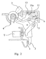
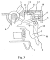
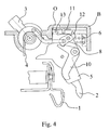
- a device for opening the fixed contacts 1 and mobile 2 of a circuit-breaker D (shown partially) housed in an insulating housing B.
- This moving contact 2 can be manually operated by a handle 3 pivotally mounted between a position closure and an open position of the contacts 1,2, said lever 3 being recalled in opening position by a handle spring 4 and being connected to a support device 5 mobile contact 2, or platinum, said platen 5 being biased to the open position of the contact 2 by a spring 6.
- This movable contact 2 can also be actuated automatically via a mechanism M comprising the support device 5 of the movable contact 2, which is rotatably mounted between the two aforementioned positions and being connected to the handle 3 by a moving element E so as to form between the device 5 and the lever 3 a breakable mechanical connection.
- This mechanical connection comprises a transmission rod 7 articulated by one of its ends on the handle 3, and by its other end, on a hook 8 articulated on the plate 5 and cooperating with a means of trigger 9.
- This triggering means 9 comprises a trigger lever 10 controlled by a trigger T to cause, in the event of an electrical fault, the rupture of the mechanical connection that triggers the automatic triggering of the mechanism M and the separation of the contacts 1,2, independently of the joystick 3.
- a means for recalling the triggering means 9 to an armed position allows automatic reset of the mechanism when the handle 3 is in the open position.
- the apparatus also comprises a signaling means S of the triggered state of circuit breaker D.
- This signaling means S comprises a shutter 11 slidably mounted in translation into the upper wall of the housing B of the circuit breaker D and cooperating with a O opening provided in the housing B.
- This flap 11 is intended to cooperate with a leg 12 secured to the aforementioned hook 8 and with a heel 13 belonging to the plate 5 in a manner which will be described in the following.
- the apparatus D is in the open position, the fixed and movable contacts 1 and 2 being separated by manual opening.
- the rotation of the joystick 3 has led the rotation of the plate 5 in the counterclockwise direction.
- the hook 8 practically does not no change of position with respect to the plate 5.
- the configuration of the hook 8 and the bar 10, or lever, are such that no contact has been established between the tab 12 of the hook 8 and the flap 11, which remains in a so-called high position indicating that no triggering following a fault has occurred.
- the profile of the mobile equipment E in this position is shown in Figure 5.
- an automatic opening by unlocking has taken place following the appearance an electrical fault.
- the trigger T causes in rotation the trigger bar 10, which releases the hook 8 from its engagement with the trigger bar 10.
- the hook 8 thus released, the plate 5 can be driven in rotation in the direction of the opening of the contacts 1,2, being recalled in this position by the return spring 6.
- the speed of each element is a function of its inertia and the spring force of this element.
- the inertia of the hook 8 is less than that of the handle and the restoring force of the return spring 6 of the plate 5 is set to be greater than the return force of the spring 4 of the joystick 3.
- the speed the rotation of the hook 8 is greater than the speed of rotation of the handle 3.
- the release of the rotating plate 5 causes the hook 8 in a rapid movement of rotation.
- the tab 12 of the hook 8 drives the shutter 11 in translation to a position illustrated in Figure 3, in which the flap 11 is next to the opening O of the housing B, position of the flap 11 indicating an opening by unlocking of the mechanism M.
- the profile of the moving element E in this position is represented on the Figure 6.
- the handle 3 delayed by its high inertia and the low force of recall of its return spring 4 remained virtually immobile.
- the handle 3 is recalled slowly in the open position shown in Figure 4.
- the hook 8 is rotated in the direction of clockwise and the flap 11 remains in the down position as shown in Figure 4, to signal a default opening of the mechanism.
- the heel 13 of the plate 5 will result in again the flap 11 in the high position as illustrated in Figure 2.
- a device for signaling the opening of a device for example a circuit-breaker, only if this opening is caused by the unlocking its mechanism M during a fault of the overload, short-circuit type, or when the order of a suitable auxiliary is sent, this signaling device being built into the product. It is no longer necessary to use an accessory additional information and the taking of information is carried out at the level of a single element, the a simplification of the design of the apparatus comprising this function of signaling.
- the mechanism state signaling system according to the invention is related to its sequence of operation.
- the identification of the sequence of operation is carried out thanks to differential speeds of the elements, said speeds being determined by the inertia of said elements and the return forces of their spring.
- sequence memory can be erased either automatically by closing the handle or by another body separate.
- the LED can also be provide the classic open / closed signaling function by adding a third intermediate position to the indicator 11 and a second heel facing the 13 on the plate 5.
- the invention applies to any device such as a circuit breaker or a differential switch and generally to any device which provides a trigger by any means other than manual opening.
- the invention includes all the technical equivalents of the means thus described. that their combinations if they are carried out according to his spirit.
Landscapes
- Switch Cases, Indication, And Locking (AREA)
- Breakers (AREA)
Applications Claiming Priority (2)
| Application Number | Priority Date | Filing Date | Title |
|---|---|---|---|
| FR0314339A FR2863403B1 (fr) | 2003-12-08 | 2003-12-08 | Dispositif de signalisation du declenchement d'un appareil de protection electrique et appareil de protection electrique le comportant |
| FR0314339 | 2003-12-08 |
Publications (2)
| Publication Number | Publication Date |
|---|---|
| EP1542253A1 true EP1542253A1 (de) | 2005-06-15 |
| EP1542253B1 EP1542253B1 (de) | 2006-11-22 |
Family
ID=34508609
Family Applications (1)
| Application Number | Title | Priority Date | Filing Date |
|---|---|---|---|
| EP20040354033 Active EP1542253B1 (de) | 2003-12-08 | 2004-09-10 | Anzeigeeinrichtung einer Auslöseeinrichtung eines elektrischen Schutzgeräts |
Country Status (4)
| Country | Link |
|---|---|
| EP (1) | EP1542253B1 (de) |
| DE (1) | DE602004003328T2 (de) |
| ES (1) | ES2275196T3 (de) |
| FR (1) | FR2863403B1 (de) |
Cited By (10)
| Publication number | Priority date | Publication date | Assignee | Title |
|---|---|---|---|---|
| EP2083434A1 (de) * | 2008-01-28 | 2009-07-29 | Hager-Electro SAS | Warnsystem zur Signalisierung eines elektrischen Defekts in einem Unterbrechungsapparat |
| FR2931998A1 (fr) * | 2008-06-03 | 2009-12-04 | Schneider Electric Ind Sas | Dispositif de commande d'un appareil de coupure electrique comportant un dispositif de signalisation de la soudure des contacts, et appareil de coupure electrique comportant un tel dispositif |
| CN101042961B (zh) * | 2006-03-21 | 2010-10-13 | 陈庆荣 | 具有特殊触头结构的电器元件 |
| EP2242078A1 (de) * | 2009-04-15 | 2010-10-20 | Eaton Corporation | Mechanismus oder rückstellbarer Auslöseanzeigemechanismus für einen Schutzschalter und Schutzschalter damit |
| CN103337428A (zh) * | 2013-05-31 | 2013-10-02 | 浙江天正电气股份有限公司 | 带故障指示装置的小型断路器 |
| CN103346047A (zh) * | 2013-05-30 | 2013-10-09 | 浙江天正电气股份有限公司 | 一种带故障脱扣指示装置的小型断路器 |
| CN104505307A (zh) * | 2014-12-29 | 2015-04-08 | 德力西电气有限公司 | 一种脱扣指示机构以及具有其的脱扣器 |
| EP2975628A1 (de) | 2014-07-17 | 2016-01-20 | Schneider Electric Industries SAS | Vorrichtung zur signalisierung einer elektrischen störung in einem elektrischen schutzgerät, und gerät, das eine solche vorrichtung umfasst |
| CN106158523A (zh) * | 2015-03-30 | 2016-11-23 | 上海良信电器股份有限公司 | 一种断路器故障脱扣指示机构 |
| CN106158525A (zh) * | 2016-08-31 | 2016-11-23 | 厦门宏发开关设备有限公司 | 一种断路器 |
Families Citing this family (7)
| Publication number | Priority date | Publication date | Assignee | Title |
|---|---|---|---|---|
| CN102064054B (zh) * | 2009-11-12 | 2014-02-26 | 施耐德电器工业公司 | 热电磁式脱扣器及其跳扣机构 |
| DE102015207802A1 (de) * | 2015-04-28 | 2016-11-03 | DEHN + SÖHNE GmbH + Co. KG. | Auslösung eines Störlichtbogenschutzsystems |
| DE102015110406B4 (de) | 2015-06-29 | 2020-01-09 | Abb Ag | Elektrisches Installationsschaltgerät mit einer Schaltstellungsanzeige |
| DE102016123957A1 (de) * | 2016-12-09 | 2018-06-14 | Eaton Industries (Austria) Gmbh | Schutzschalter |
| FR3123142A1 (fr) | 2021-05-20 | 2022-11-25 | Schneider Electric Industries Sas | Appareils et systèmes de protection électrique comportant un module de coupure intégré |
| FR3123141A1 (fr) | 2021-05-20 | 2022-11-25 | Schneider Electric Industries Sas | Appareils et systèmes de protection électrique |
| FR3134226A1 (fr) | 2022-04-04 | 2023-10-06 | Schneider Electric Industries Sas | Appareil de protection électrique modulaire avec modules de commande et de puissance |
Citations (2)
| Publication number | Priority date | Publication date | Assignee | Title |
|---|---|---|---|---|
| FR2616583A1 (fr) * | 1987-06-09 | 1988-12-16 | Merlin Gerin | Mecanisme de commande d'un disjoncteur electrique miniature |
| EP0408466A2 (de) * | 1989-07-11 | 1991-01-16 | Merlin Gerin | Betätigungsmechanismus für elektrischen Schalter |
-
2003
- 2003-12-08 FR FR0314339A patent/FR2863403B1/fr not_active Expired - Lifetime
-
2004
- 2004-09-10 DE DE200460003328 patent/DE602004003328T2/de active Active
- 2004-09-10 EP EP20040354033 patent/EP1542253B1/de active Active
- 2004-09-10 ES ES04354033T patent/ES2275196T3/es active Active
Patent Citations (2)
| Publication number | Priority date | Publication date | Assignee | Title |
|---|---|---|---|---|
| FR2616583A1 (fr) * | 1987-06-09 | 1988-12-16 | Merlin Gerin | Mecanisme de commande d'un disjoncteur electrique miniature |
| EP0408466A2 (de) * | 1989-07-11 | 1991-01-16 | Merlin Gerin | Betätigungsmechanismus für elektrischen Schalter |
Cited By (20)
| Publication number | Priority date | Publication date | Assignee | Title |
|---|---|---|---|---|
| CN101042961B (zh) * | 2006-03-21 | 2010-10-13 | 陈庆荣 | 具有特殊触头结构的电器元件 |
| EP2083434A1 (de) * | 2008-01-28 | 2009-07-29 | Hager-Electro SAS | Warnsystem zur Signalisierung eines elektrischen Defekts in einem Unterbrechungsapparat |
| FR2926923A1 (fr) * | 2008-01-28 | 2009-07-31 | Hager Electro S A S Soc Par Ac | Systeme de signalisation d'un defaut electrique dans un appareil de coupure |
| WO2009095614A2 (fr) * | 2008-01-28 | 2009-08-06 | Hager-Electro Sas | Systeme de signalisation d'un defaut electrique dans un appareil de coupure |
| WO2009095614A3 (fr) * | 2008-01-28 | 2009-11-05 | Hager-Electro Sas | Systeme de signalisation d'un defaut electrique dans un appareil de coupure |
| CN101933110A (zh) * | 2008-01-28 | 2010-12-29 | 黑格电子股份有限公司 | 断路装置中的电故障信号系统 |
| CN104409290A (zh) * | 2008-01-28 | 2015-03-11 | 黑格电子股份有限公司 | 断路装置中的电故障信号系统 |
| FR2931998A1 (fr) * | 2008-06-03 | 2009-12-04 | Schneider Electric Ind Sas | Dispositif de commande d'un appareil de coupure electrique comportant un dispositif de signalisation de la soudure des contacts, et appareil de coupure electrique comportant un tel dispositif |
| EP2131378A1 (de) * | 2008-06-03 | 2009-12-09 | Schneider Electric Industries SAS | Steuervorrichtung für ein elektrisches Unterbrechungsgerät, das mit einer Signalisierungsvorrichtung für die Verschweißung der Kontakte ausgestattet ist, und mit dieser Vorrichtung ausgestattetes elektrisches Unterbrechungsgerät |
| EP2242078A1 (de) * | 2009-04-15 | 2010-10-20 | Eaton Corporation | Mechanismus oder rückstellbarer Auslöseanzeigemechanismus für einen Schutzschalter und Schutzschalter damit |
| CN103346047A (zh) * | 2013-05-30 | 2013-10-09 | 浙江天正电气股份有限公司 | 一种带故障脱扣指示装置的小型断路器 |
| CN103337428A (zh) * | 2013-05-31 | 2013-10-02 | 浙江天正电气股份有限公司 | 带故障指示装置的小型断路器 |
| CN103337428B (zh) * | 2013-05-31 | 2015-11-18 | 浙江天正电气股份有限公司 | 带故障指示装置的小型断路器 |
| EP2975628A1 (de) | 2014-07-17 | 2016-01-20 | Schneider Electric Industries SAS | Vorrichtung zur signalisierung einer elektrischen störung in einem elektrischen schutzgerät, und gerät, das eine solche vorrichtung umfasst |
| CN104505307A (zh) * | 2014-12-29 | 2015-04-08 | 德力西电气有限公司 | 一种脱扣指示机构以及具有其的脱扣器 |
| CN104505307B (zh) * | 2014-12-29 | 2017-04-19 | 德力西电气有限公司 | 一种脱扣指示机构和具有其的脱扣器 |
| CN106158523A (zh) * | 2015-03-30 | 2016-11-23 | 上海良信电器股份有限公司 | 一种断路器故障脱扣指示机构 |
| CN106158523B (zh) * | 2015-03-30 | 2019-02-05 | 上海良信电器股份有限公司 | 一种断路器故障脱扣指示机构 |
| CN106158525A (zh) * | 2016-08-31 | 2016-11-23 | 厦门宏发开关设备有限公司 | 一种断路器 |
| CN106158525B (zh) * | 2016-08-31 | 2019-02-26 | 厦门宏发开关设备有限公司 | 一种断路器 |
Also Published As
| Publication number | Publication date |
|---|---|
| FR2863403B1 (fr) | 2006-01-20 |
| FR2863403A1 (fr) | 2005-06-10 |
| ES2275196T3 (es) | 2007-06-01 |
| EP1542253B1 (de) | 2006-11-22 |
| DE602004003328D1 (de) | 2007-01-04 |
| DE602004003328T2 (de) | 2007-04-26 |
Similar Documents
| Publication | Publication Date | Title |
|---|---|---|
| EP1542253B1 (de) | Anzeigeeinrichtung einer Auslöseeinrichtung eines elektrischen Schutzgeräts | |
| EP0394144B1 (de) | Hilfsschalter mit manueller Überprüfung für einen modularen Schutzschalter | |
| EP2975628B1 (de) | Vorrichtung zur signalisierung einer elektrischen störung in einem elektrischen schutzgerät, und gerät, das eine solche vorrichtung umfasst | |
| EP0935272B1 (de) | Auslösevorrichtung für Schutzschalter mit Signalisierung von Elektrische fehlern | |
| FR2914485A1 (fr) | Dispositif de commande d'un appareil de protection electrique et appareil de protection electrique la comportant | |
| CA2186772A1 (fr) | Dispositif de commande et de signalisation pour appareil interrupteur de protection | |
| EP2131378A1 (de) | Steuervorrichtung für ein elektrisches Unterbrechungsgerät, das mit einer Signalisierungsvorrichtung für die Verschweißung der Kontakte ausgestattet ist, und mit dieser Vorrichtung ausgestattetes elektrisches Unterbrechungsgerät | |
| EP0161946B1 (de) | An einen Schutzschalter ankuppelbare Zusatzeinheit | |
| EP1065691B1 (de) | Hilfsmodul zur Signalisierung für elektrisches Gerät mit Auslöser | |
| EP0657909B1 (de) | Elektrischer Schalter mit Fehlerauslösung | |
| EP2717284B1 (de) | Bedienungsvorrichtung eines elektrischen Schutzschaltgeräts, und diese umfassendes elektrisches Schutzschaltgerät | |
| EP2518752B1 (de) | Anzeiger der Störungsauslösung durch die Position des Handsteuerhebels | |
| FR3051593B1 (fr) | Dispositif de signalisation d'un defaut electrique dans un appareil de protection electrique, et appareil de protection electrique comportant un tel dispositif. | |
| CH686853A5 (fr) | Appareil interrupteur de protection accouplable à un module de commande et/ou à un module de signalisation. | |
| FR2701595A1 (fr) | Disjoncteur à bloc de télécommande adaptable. | |
| FR2684231A1 (fr) | Appareils auxiliaires de disjoncteurs electriques. | |
| EP1274109A1 (de) | Betätigungsmechanismus für einen Lastschalter | |
| EP0461027B1 (de) | Differential Auslösevorrichtung | |
| EP2642502B1 (de) | Auslöseblock für elektrisches Sicherungsgerät, und mit einem solchen Block ausgestattetes elektrisches Sicherungsgerät | |
| EP0200581B1 (de) | Fehlerstromschutzschaltermechanismen die ihre Kupplung in oder an Selbstausschaltern erlauben | |
| EP0079817B1 (de) | Kniehebelmechanismus mit Freiauslösung für Differentialschutzschalter und dergleichen und Differentialschutzschalter mit derartigem Mechanismus | |
| EP0248702B1 (de) | Verfahren und Einrichtung zum Regeln des thermischen Stromes eines thermischen Bimetallauslösers für Schutzschalter | |
| EP0327460A1 (de) | Elektrischer Schalter mit automatischer Ausschaltung, insbesondere Differentialschutz | |
| FR2553572A1 (fr) | Interrupteur differentiel perfectionne a encombrement reduit | |
| FR2766292A1 (fr) | Dispositif de commande d'un appareil de protection electrique tel un disjoncteur comprenant un moyen de signalisation du declenchement, et disjoncteur equipe d'un tel dispositif |
Legal Events
| Date | Code | Title | Description |
|---|---|---|---|
| PUAI | Public reference made under article 153(3) epc to a published international application that has entered the european phase |
Free format text: ORIGINAL CODE: 0009012 |
|
| AK | Designated contracting states |
Kind code of ref document: A1 Designated state(s): AT BE BG CH CY CZ DE DK EE ES FI FR GB GR HU IE IT LI LU MC NL PL PT RO SE SI SK TR |
|
| AX | Request for extension of the european patent |
Extension state: AL HR LT LV MK |
|
| 17P | Request for examination filed |
Effective date: 20050916 |
|
| AKX | Designation fees paid |
Designated state(s): DE ES GB IT |
|
| GRAP | Despatch of communication of intention to grant a patent |
Free format text: ORIGINAL CODE: EPIDOSNIGR1 |
|
| GRAS | Grant fee paid |
Free format text: ORIGINAL CODE: EPIDOSNIGR3 |
|
| GRAA | (expected) grant |
Free format text: ORIGINAL CODE: 0009210 |
|
| AK | Designated contracting states |
Kind code of ref document: B1 Designated state(s): DE ES GB IT |
|
| REG | Reference to a national code |
Ref country code: GB Ref legal event code: FG4D Free format text: NOT ENGLISH |
|
| REF | Corresponds to: |
Ref document number: 602004003328 Country of ref document: DE Date of ref document: 20070104 Kind code of ref document: P |
|
| GBT | Gb: translation of ep patent filed (gb section 77(6)(a)/1977) |
Effective date: 20070104 |
|
| REG | Reference to a national code |
Ref country code: ES Ref legal event code: FG2A Ref document number: 2275196 Country of ref document: ES Kind code of ref document: T3 |
|
| PLBE | No opposition filed within time limit |
Free format text: ORIGINAL CODE: 0009261 |
|
| STAA | Information on the status of an ep patent application or granted ep patent |
Free format text: STATUS: NO OPPOSITION FILED WITHIN TIME LIMIT |
|
| 26N | No opposition filed |
Effective date: 20070823 |
|
| PGFP | Annual fee paid to national office [announced via postgrant information from national office to epo] |
Ref country code: IT Payment date: 20230920 Year of fee payment: 20 Ref country code: GB Payment date: 20230926 Year of fee payment: 20 |
|
| PGFP | Annual fee paid to national office [announced via postgrant information from national office to epo] |
Ref country code: DE Payment date: 20230928 Year of fee payment: 20 |
|
| PGFP | Annual fee paid to national office [announced via postgrant information from national office to epo] |
Ref country code: ES Payment date: 20231017 Year of fee payment: 20 |