EP1541973B1 - Débitmètre magnéto-inductif et procédé de mesure pour un débitmètre magnéto-inductif - Google Patents
Débitmètre magnéto-inductif et procédé de mesure pour un débitmètre magnéto-inductif Download PDFInfo
- Publication number
- EP1541973B1 EP1541973B1 EP04021992A EP04021992A EP1541973B1 EP 1541973 B1 EP1541973 B1 EP 1541973B1 EP 04021992 A EP04021992 A EP 04021992A EP 04021992 A EP04021992 A EP 04021992A EP 1541973 B1 EP1541973 B1 EP 1541973B1
- Authority
- EP
- European Patent Office
- Prior art keywords
- measuring
- preamplifier
- electrode
- reference electrode
- differential amplifier
- Prior art date
- Legal status (The legal status is an assumption and is not a legal conclusion. Google has not performed a legal analysis and makes no representation as to the accuracy of the status listed.)
- Not-in-force
Links
Images

Classifications
-
- G—PHYSICS
- G01—MEASURING; TESTING
- G01F—MEASURING VOLUME, VOLUME FLOW, MASS FLOW OR LIQUID LEVEL; METERING BY VOLUME
- G01F1/00—Measuring the volume flow or mass flow of fluid or fluent solid material wherein the fluid passes through a meter in a continuous flow
- G01F1/56—Measuring the volume flow or mass flow of fluid or fluent solid material wherein the fluid passes through a meter in a continuous flow by using electric or magnetic effects
- G01F1/58—Measuring the volume flow or mass flow of fluid or fluent solid material wherein the fluid passes through a meter in a continuous flow by using electric or magnetic effects by electromagnetic flowmeters
- G01F1/60—Circuits therefor
Definitions
- the invention relates to a magnetic-inductive flowmeter for measuring the volume flow of a medium flowing through a measuring tube, with a magnet for generating a magnetic field passing through the measuring tube with a perpendicular to the flow direction magnetic field component, a first measuring electrode and a second measuring electrode for tapping a in the Medium induced voltage, a reference electrode and a preamplifier, on which the tapped off at the two measuring electrodes potentials are performed.
- the invention also relates to a measuring method for a magnetic-inductive flowmeter for measuring the volume flow of a medium flowing through a measuring tube, wherein the magnetic-inductive flowmeter comprises a magnet for generating a magnetic field passing through the measuring tube with a perpendicular to the flow direction magnetic field component, a first measuring electrode and a second measuring electrode for picking up a voltage induced in the medium, a reference electrode and a preamplifier to which the tapped off at the two measuring electrodes potentials are performed.
- the terms “voltage” and “potential” are used to refer to a “voltage” when a concrete potential difference between two points is meant. From “potential” is then spoken when the electrical potential of a certain point in a predetermined potential system, ie z. B. to ground or earth, to be called.
- Magnetic-inductive flowmeters and measuring methods for magnetic-inductive flow devices of the type mentioned are well known for a long time and are used in a variety of different applications.
- the basic principle of a magnetic-inductive flowmeter for measuring the volume flow of a flowing through a measuring tube medium already goes back to Faraday, which proposed in 1832 to apply the principle of electrodynamic induction for flow velocity measurement.
- the measuring electrodes are designed in the known magnetic-inductive flow measuring devices such that they are coupled either galvanically or capacitively with the flowing medium.
- a special feature of the magnetic-inductive flow measuring devices is also the proportionality between the measuring voltage on the one hand and the averaged over the cross section of the measuring tube flow rate of the medium on the other hand, that is between the measuring voltage and flow.
- the magnetic field is generally alternated over time in a magneto-inductive flowmeter.
- Different approaches are known from the prior art.
- a magnetic-inductive flow measurement is z. B. possible with an alternating field, typically the magnetic coils of the magnet are fed directly from the mains with a sinusoidal 50 Hz AC voltage.
- the voltage generated between the measuring electrodes due to the flow is easily disturbed by transformer interference voltages and mains interference voltages.
- magneto-inductive flowmeters have generally operated with a switched dc field.
- a switched DC field is obtained by the magnet coils of the magnet, a current is supplied with temporally substantially rectangular course, which changes its polarity in time alternately.
- a pulsating DC field which is obtained in that the magnet coils of the magnet are supplied only periodically with a temporally rectangular, always having the same polarity current.
- a method in which the field current is reversed periodically, that is to say a periodically alternating magnetic field is generated is preferable since disturbances such as electrochemical disturbances are suppressed by the change in the polarity of the magnetic field.
- the proportional to the flow voltage between the measuring electrodes is generally very small, namely in the microvolt range. This voltage must be measured with high resolution (about 100 nV); and the measuring frequency is in the known magnetic-inductive flowmeters, which operate on the principle of the switched DC field, in the range of 1 to 100 Hz.
- the tapped off at the measuring electrodes voltage is generally supplied to the preamplifier in the known magnetic-inductive flowmeters before the pre-amplified, proportional to the flow voltage signal is further processed.
- a preamplifier differential amplifiers are often used, which are typically operated with a supply voltage of ⁇ 15V.
- the modulation range, ie the maximum output voltage of the preamplifier is thus 15 V, namely + 15 V for positive signals and - 15 V for negative signals.
- the reference electrode of the magnetic inductive flowmeter is generally kept at a potential of 0 V, that is at ground potential.
- preamplifier for magnetic-inductive flow meters with lower supply voltages eg. B. with a supply voltage of 5 V (0 V, + 5 V) to operate.
- a control range of 0 V to 5 V would basically be possible.
- Corresponding analog components for the supply voltage range of 0 V to 5 V have become available in the meantime, highly accurate Sigma-delta converters operate with these low input voltages, and in particular, power dissipation is reduced.
- the previously derived and indicated object is achieved in that a control circuit for influencing the common mode input voltage of the preamplifier and / or the potential range of the Ausbeck Schemes of the preamplifier is provided that the common mode input voltage of the preamplifier of half the maximum output voltage of the preamplifier, wherein the control circuit is connected to the reference electrode and is provided for controlling the potential of the reference electrode.
- the invention provides that the common mode input voltage of the preamplifier is approximated to half the maximum output voltage of the preamplifier means that the difference between the common mode input voltage and the half maximum output voltage should be made as small as possible. In general, however, no complete and, in particular, no instantaneous approximation will be achieved.
- the influence of the potential range of the Aus Kunststoff Anlagens of the preamplifier means in particular that the control range, z. B. 0 V bis 5 V at a usable supply voltage of 5 V remains constant, but is moved in terms of potential, ie z. B. from 1 V to 6 V.
- the common mode input voltage of the preamplifier may be manipulated to approximate the common mode input voltage of the preamplifier to half the maximum output voltage of the preamplifier.
- control circuit with the first measuring electrode and the second measuring electrode is connected to control the potential of the reference electrode in dependence on the potentials of the measuring electrodes.
- the control circuit has an inverting differential amplifier circuit with a differential amplifier whose inverting input is connected via a first resistor to the first measuring electrode and via a second resistor to the second measuring electrode. It can be provided in particular that the non-inverting input of the differential amplifier is maintained at about half the maximum output voltage of the preamplifier. Specifically, for a preamplifier supplied with 0 V and 5 V, this would mean that the noninverting input of the differential amplifier is kept at about 2.5 volts.
- a connection with the reference electrode via the output of the control circuit takes place.
- the inverting input of the differential amplifier is connected via a negative feedback resistor to the output of the differential amplifier, wherein in particular a capacitor may be connected in parallel thereto.
- a capacitor serves the band limitation and thus the stability of the controller.
- the above-derived and indicated object is achieved in that the common mode input voltage of the amplifier and / or the potential range of the drive range of the preamplifier are influenced such that the common mode input voltage of the preamplifier of half maximum output voltage of the preamplifier is approached and the potential of the reference electrode is controlled in dependence on the potentials of the measuring electrodes.
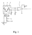
- Fig. 1 schematically shows a magnetic-inductive flowmeter for measuring the volume flow of a flowing through a measuring tube 4 medium according to a preferred embodiment of the invention.
- a measuring tube 4 is perpendicular to the flow direction enforcing magnetic field generated.
- a voltage is generated when flowing through the measuring tube 4 with an electrically conductive medium.
- This can be tapped via a first measuring electrode 2 and a second measuring electrode 3, which are in galvanic contact with the flowing medium.
- a reference electrode 1 which is in galvanic contact with the medium is provided.
- the tapped at the measuring electrodes 2, 3 voltage signal is fed to a formed as a differential amplifier preamplifier 5. This is operated with a supply voltage of 0 V / 5 V.
- FIG. 2 A concrete realization of a control circuit with which the aforementioned control method according to the preferred embodiment of the invention can be performed is Fig. 2 schematically removable.
- the control circuit is connected to the reference electrode 1, the first measuring electrode 2 and the second measuring electrode 3 in order to control the potential of the reference electrode 1 as a function of the potentials of the measuring electrodes 2, 3.
- the control circuit has an inverting differential amplifier circuit 6 with a differential amplifier 7, whose inverting input is connected via a first resistor 8 to the first measuring electrode 2 and via a second resistor 9 to the second measuring electrode 3.
- the non-inverting input of the differential amplifier 7 is maintained at about half the maximum output voltage of the preamplifier 5, in the present case at about 2.5 V, since the preamplifier 5 is supplied with 0 V / 5 V. Finally, the output of the differential amplifier 7 is guided to the reference electrode 1.
Claims (10)
- Débitmètre magnéto-inductif pour mesurer le débit volumique d'un fluide qui circule à travers un tube de mesure (4), comprenant un aimant pour générer un champ magnétique qui charge le tube de mesure (4) avec une composante de champ magnétique s'étendant perpendiculairement au sens de l'écoulement, une première électrode de mesure (2) et une deuxième électrode de mesure (3) pour prélever une tension induite dans le fluide, une électrode de référence (1) et un préamplificateur (5) auquel sont acheminés les potentiels prélevés sur les deux électrodes de mesure (2, 3), caractérisé en ce qu'il est prévu un circuit de commande pour influencer la tension d'entrée en mode commun du préamplificateur (5) et/ou la plage de potentiels de la plage d'excitation du préamplificateur (5) de telle sorte que la tension d'entrée en mode commun du préamplificateur (5) s'approche de la moitié de la tension de sortie maximale du préamplificateur (5), le circuit de commande étant relié avec l'électrode de référence (1) et étant prévu pour commander le potentiel de l'électrode de référence (1).
- Débitmètre magnéto-inductif selon la revendication 1, caractérisé en ce que le circuit de commande est relié avec la première électrode de mesure (2) et la deuxième électrode de mesure (3) pour commander le potentiel de l'électrode de référence (1) en fonction des potentiels des électrodes de mesure (2, 3) .
- Débitmètre magnéto-inductif selon la revendication 2, caractérisé en ce que le circuit de commande présente un circuit amplificateur différentiel inverseur (6) avec un amplificateur différentiel (7) dont l'entrée inverseuse est reliée avec la première électrode de mesure (2) par le biais d'une première résistance (8) et avec la deuxième électrode de mesure (3) par le biais d'une deuxième résistance (9).
- Débitmètre magnéto-inductif selon la revendication 3, caractérisé en ce que l'entrée non inverseuse de l'amplificateur différentiel (7) est maintenue à environ la moitié de la tension de sortie maximale du préamplificateur (5).
- Débitmètre magnéto-inductif selon la revendication 3 ou 4, caractérisé en ce que la sortie de l'amplificateur différentiel (7) est acheminée à l'électrode de référence (1).
- Débitmètre magnéto-inductif selon l'une des revendications 3 à 5, caractérisé en ce qu'il est prévu une résistance de contre-réaction (10) qui relie l'entrée inverseuse de l' amplificateur différentiel (7) avec la sortie de l'amplificateur différentiel (7) et un condensateur (11) est de préférence branché en parallèle avec la résistance de contre-réaction (10).
- Débitmètre magnéto-inductif selon l'une des revendications 1 à 6, caractérisé en ce qu'un amplificateur différentiel est prévu en tant que préamplificateur (5).
- Procédé de mesure pour un débitmètre magnéto-inductif pour mesurer le débit volumique d'un fluide qui circule à travers un tube de mesure (4), le débitmètre magnéto-inductif présentant un aimant pour générer un champ magnétique qui charge le tube de mesure (4) avec une composante de champ magnétique s'étendant perpendiculairement au sens de l'écoulement, une première électrode de mesure (2) et une deuxième électrode de mesure (3) pour prélever une tension induite dans le fluide, une électrode de référence (1) et un préamplificateur (5) auquel sont acheminés les potentiels prélevés sur les deux électrodes de mesure (2, 3), caractérisé en ce que la tension d'entrée en mode commun du préamplificateur et/ou la plage de potentiels de la plage d'excitation du préamplificateur (5) sont influencées de telle sorte que la tension d'entrée en mode commun du préamplificateur (5) s'approche de la moitié de la tension de sortie maximale du préamplificateur (5) et le potentiel de l'électrode de référence (1) est commandé en fonction des potentiels des électrodes de mesure (2, 3).
- Procédé de mesure selon la revendication 8,
caractérisé en ce que pour commander le potentiel de l'électrode de référence (1) en fonction des potentiels des électrodes de mesure (2, 3) on utilise un circuit amplificateur différentiel (6) avec un amplificateur différentiel (7) dont l'entrée inverseuse est reliée avec la première électrode de mesure (2) par le biais d'une première résistance (8) et avec la deuxième électrode de mesure (3) par le biais d'une deuxième résistance (9), dont l'entrée non inverseuse est maintenue à environ la moitié de la tension de sortie maximale du préamplificateur (5), dont l'entrée inverseuse est reliée à sa sortie par le biais d'une résistance de contre-réaction (10) et dont la sortie est acheminée à l'électrode de référence (1). - Procédé de mesure selon la revendication 9, caractérisé en ce qu'un condensateur (11) branché en parallèle avec la résistance de contre-réaction (10) est utilisé pour la limitation de la bande.
Applications Claiming Priority (2)
| Application Number | Priority Date | Filing Date | Title |
|---|---|---|---|
| DE10357514A DE10357514B3 (de) | 2003-12-08 | 2003-12-08 | Magnetisch-induktives Durchflußmeßgerät und Meßverfahren für ein magnetisch-induktives Durchflußmeßgerät |
| DE10357514 | 2003-12-08 |
Publications (2)
| Publication Number | Publication Date |
|---|---|
| EP1541973A1 EP1541973A1 (fr) | 2005-06-15 |
| EP1541973B1 true EP1541973B1 (fr) | 2008-11-12 |
Family
ID=34306438
Family Applications (1)
| Application Number | Title | Priority Date | Filing Date |
|---|---|---|---|
| EP04021992A Not-in-force EP1541973B1 (fr) | 2003-12-08 | 2004-09-16 | Débitmètre magnéto-inductif et procédé de mesure pour un débitmètre magnéto-inductif |
Country Status (6)
| Country | Link |
|---|---|
| US (1) | US7174256B2 (fr) |
| EP (1) | EP1541973B1 (fr) |
| JP (1) | JP4063817B2 (fr) |
| AT (1) | ATE414260T1 (fr) |
| DE (2) | DE10357514B3 (fr) |
| DK (1) | DK1541973T3 (fr) |
Cited By (1)
| Publication number | Priority date | Publication date | Assignee | Title |
|---|---|---|---|---|
| CN109141551A (zh) * | 2018-09-27 | 2019-01-04 | 麦克传感器股份有限公司 | 陶瓷衬里电磁流量计传感器高压电极封装结构 |
Families Citing this family (8)
| Publication number | Priority date | Publication date | Assignee | Title |
|---|---|---|---|---|
| DE102005018179A1 (de) * | 2005-04-19 | 2006-10-26 | Krohne Messtechnik Gmbh & Co. Kg | Verfahren zum Betrieb eines Meßgeräts |
| DE102012106926A1 (de) | 2012-07-30 | 2014-05-15 | Endress + Hauser Flowtec Ag | Meßelektronik sowie damit gebildetes Meßsystem |
| DE102013105832B4 (de) * | 2013-06-06 | 2015-03-12 | Zylum Beteiligungsgesellschaft Mbh & Co. Patente Ii Kg | Vorrichtung und Verfahren zur magnetisch-induktiven Durchflussmessung |
| CN103335678A (zh) * | 2013-07-24 | 2013-10-02 | 中环天仪股份有限公司 | 一种电磁流量计量程自动切换的控制方法 |
| JP2015105929A (ja) * | 2013-12-02 | 2015-06-08 | 株式会社東芝 | 電磁流量計 |
| US10024707B2 (en) * | 2016-02-17 | 2018-07-17 | Schneider Electric Systems Usa, Inc. | Electromagnetic flowmeter calibration verification |
| DE102019107904B3 (de) * | 2019-03-27 | 2020-08-13 | Krohne Messtechnik Gmbh | Magnetisch-induktives Durchflussmessgerät mit Leitfähigkeitsmesseinrichtung und Verfahren zum Betreiben eines magnetisch-induktiven Durchflussmessgerätes mit Leitfähigkeitsmesseinrichtung |
| US11131571B2 (en) * | 2019-07-22 | 2021-09-28 | Georg Fischer Signett LLC | Magnetic flowmeter assembly with glitch removing capability |
Citations (1)
| Publication number | Priority date | Publication date | Assignee | Title |
|---|---|---|---|---|
| DE19716151C1 (de) * | 1997-04-01 | 1998-08-20 | Krohne Messtechnik Kg | Magnetisch-induktives Durchflußmeßgerät für strömende Medien |
Family Cites Families (8)
| Publication number | Priority date | Publication date | Assignee | Title |
|---|---|---|---|---|
| DE2410407C3 (de) * | 1974-03-05 | 1981-05-21 | Fa. Ludwig Krohne, 4100 Duisburg | Verfahren zur Kompensation der elektrochemischen Störgleichspannung bei der induktiven Durchflußmessung mit periodisch zwischen zwei Induktionswerten hin- und hergeschaltetem Gleichfeld |
| GB2186373B (en) * | 1986-02-06 | 1990-06-06 | Danfoss As | Electromagnetic flowmeters and flowmetering methods |
| ES2078995T3 (es) * | 1991-06-08 | 1996-01-01 | Flowtec Ag | Medidor de caudal magnetico-inductivo. |
| EP0869336B1 (fr) * | 1997-04-01 | 2008-08-13 | Krohne Messtechnik Gmbh & Co. Kg | Débitmètre électromagnétique pour milieux en écoulement |
| GB2324606B (en) * | 1997-04-25 | 2002-01-16 | Kent Meters Ltd | Electromagnetic flowmeter |
| US6973840B2 (en) * | 1999-10-06 | 2005-12-13 | Cushing Vincent J | Comprehensive electromagnetic flowmeter |
| JP2001324361A (ja) | 2000-05-12 | 2001-11-22 | Aichi Tokei Denki Co Ltd | 電磁流量計 |
| WO2004070323A1 (fr) * | 2003-02-10 | 2004-08-19 | Gambro Lundia Ab | Capteur de flux et procede pour mesurer une composante de vitesse d'ecoulement d'un fluide contenant des elements charges electriquement |
-
2003
- 2003-12-08 DE DE10357514A patent/DE10357514B3/de not_active Expired - Fee Related
-
2004
- 2004-09-16 DK DK04021992T patent/DK1541973T3/da active
- 2004-09-16 EP EP04021992A patent/EP1541973B1/fr not_active Not-in-force
- 2004-09-16 AT AT04021992T patent/ATE414260T1/de not_active IP Right Cessation
- 2004-09-16 DE DE502004008443T patent/DE502004008443D1/de active Active
- 2004-11-01 US US10/978,496 patent/US7174256B2/en not_active Expired - Fee Related
- 2004-12-07 JP JP2004354341A patent/JP4063817B2/ja not_active Expired - Fee Related
Patent Citations (1)
| Publication number | Priority date | Publication date | Assignee | Title |
|---|---|---|---|---|
| DE19716151C1 (de) * | 1997-04-01 | 1998-08-20 | Krohne Messtechnik Kg | Magnetisch-induktives Durchflußmeßgerät für strömende Medien |
Cited By (1)
| Publication number | Priority date | Publication date | Assignee | Title |
|---|---|---|---|---|
| CN109141551A (zh) * | 2018-09-27 | 2019-01-04 | 麦克传感器股份有限公司 | 陶瓷衬里电磁流量计传感器高压电极封装结构 |
Also Published As
| Publication number | Publication date |
|---|---|
| EP1541973A1 (fr) | 2005-06-15 |
| US20050125168A1 (en) | 2005-06-09 |
| DE10357514B3 (de) | 2005-04-14 |
| JP2005172826A (ja) | 2005-06-30 |
| US7174256B2 (en) | 2007-02-06 |
| JP4063817B2 (ja) | 2008-03-19 |
| DE502004008443D1 (de) | 2008-12-24 |
| DK1541973T3 (da) | 2009-03-16 |
| ATE414260T1 (de) | 2008-11-15 |
Similar Documents
| Publication | Publication Date | Title |
|---|---|---|
| EP1584902B1 (fr) | Débitmètre électromagnétique et procédé de fontionnement d'un débitmètre électromagnétique | |
| DE2744845C3 (de) | Verfahren zur Kompensation der elektrochemischen Störgleichspannung bei der magnetisch-induktiven Durchflußmessung mit periodisch umgepoltem magnetischem Gleichfeld | |
| EP3150974B1 (fr) | Procede de reglage de l'intensite constante d'un champ magnetique sur un debitmetre inductif magnetique et debitmetre inductif magnetique correspondant | |
| EP1536211B1 (fr) | Procédé pour faire fonctionner un débitmètre magnéto-inductif | |
| EP1792144A1 (fr) | Procede de controle d'un debitmetre magneto-inductif | |
| EP1541973B1 (fr) | Débitmètre magnéto-inductif et procédé de mesure pour un débitmètre magnéto-inductif | |
| EP1249687A2 (fr) | Débitmètre magnéto-inductif et procédé de mesure de débit magnéto-inductif | |
| DE10118002B4 (de) | Magnetisch-induktives Durchflußmeßverfahren und magnetisch-induktives Durchflußmeßgerät | |
| DE2118092C2 (de) | Vorverstärker für einen magnetischen Durchflußmesser | |
| EP0917644A1 (fr) | Appareil magneto-inductif de mesure du debit de milieux en ecoulement | |
| DE19938160C2 (de) | Magnetisch-induktives Durchflußmeßverfahren und Durchflußmeßgerät | |
| EP0869336B1 (fr) | Débitmètre électromagnétique pour milieux en écoulement | |
| EP1536210A2 (fr) | Procédé de fonctionnement d'un appareil de mesure | |
| EP1431716A1 (fr) | Débitmètre électromagnétique | |
| EP1363108B1 (fr) | Méthode pour déterminer l'incertitude d'un débitmètre magnéto-inductif | |
| DE102017107417A1 (de) | Verfahren zum Regeln eines in einer Spulenanordnung fließenden Spulenstroms und eine Schaltungsanordnung | |
| EP3376176B1 (fr) | Procédé de détermination de profilé d'écoulement, transducteur, débitmètre à induction magnétique et utilisation d'un débitmètre à induction magnétique | |
| DE19716151C1 (de) | Magnetisch-induktives Durchflußmeßgerät für strömende Medien | |
| DE102004056384A1 (de) | Verfahren zur Offseteliminierung aus Signalen magnetoresistiver Sensoren | |
| EP0137896B1 (fr) | Circuit pour compenser les variations du facteur de transfert d'une sonde linéaire de champ magnétique | |
| EP1348936B1 (fr) | Procédé de mesure de débit magnéto-inductif | |
| DE10356009B4 (de) | Magnetisch-induktives Durchflußmeßgerät und Verfahren zum Betreiben eines magnetisch-induktiven Durchflußmeßgeräts | |
| EP2906912A1 (fr) | Procédé d'utilisation d'un débitmètre magnéto-inductif | |
| EP1273891A1 (fr) | Procédé d'alimentation d'un débitmètre électromagnétique | |
| EP1273892A1 (fr) | Procédé pour activer un débitmètre électromagnétique |
Legal Events
| Date | Code | Title | Description |
|---|---|---|---|
| PUAI | Public reference made under article 153(3) epc to a published international application that has entered the european phase |
Free format text: ORIGINAL CODE: 0009012 |
|
| AK | Designated contracting states |
Kind code of ref document: A1 Designated state(s): AT BE BG CH CY CZ DE DK EE ES FI FR GB GR HU IE IT LI LU MC NL PL PT RO SE SI SK TR |
|
| AX | Request for extension of the european patent |
Extension state: AL HR LT LV MK |
|
| 17P | Request for examination filed |
Effective date: 20051107 |
|
| AKX | Designation fees paid |
Designated state(s): AT BE BG CH CY CZ DE DK EE ES FI FR GB GR HU IE IT LI LU MC NL PL PT RO SE SI SK TR |
|
| 17Q | First examination report despatched |
Effective date: 20061123 |
|
| GRAP | Despatch of communication of intention to grant a patent |
Free format text: ORIGINAL CODE: EPIDOSNIGR1 |
|
| GRAS | Grant fee paid |
Free format text: ORIGINAL CODE: EPIDOSNIGR3 |
|
| GRAA | (expected) grant |
Free format text: ORIGINAL CODE: 0009210 |
|
| AK | Designated contracting states |
Kind code of ref document: B1 Designated state(s): AT BE BG CH CY CZ DE DK EE ES FI FR GB GR HU IE IT LI LU MC NL PL PT RO SE SI SK TR |
|
| REG | Reference to a national code |
Ref country code: GB Ref legal event code: FG4D Free format text: NOT ENGLISH |
|
| REG | Reference to a national code |
Ref country code: CH Ref legal event code: EP |
|
| REG | Reference to a national code |
Ref country code: IE Ref legal event code: FG4D Free format text: LANGUAGE OF EP DOCUMENT: GERMAN |
|
| REF | Corresponds to: |
Ref document number: 502004008443 Country of ref document: DE Date of ref document: 20081224 Kind code of ref document: P |
|
| REG | Reference to a national code |
Ref country code: DK Ref legal event code: T3 |
|
| PG25 | Lapsed in a contracting state [announced via postgrant information from national office to epo] |
Ref country code: ES Free format text: LAPSE BECAUSE OF FAILURE TO SUBMIT A TRANSLATION OF THE DESCRIPTION OR TO PAY THE FEE WITHIN THE PRESCRIBED TIME-LIMIT Effective date: 20090223 |
|
| PG25 | Lapsed in a contracting state [announced via postgrant information from national office to epo] |
Ref country code: FI Free format text: LAPSE BECAUSE OF FAILURE TO SUBMIT A TRANSLATION OF THE DESCRIPTION OR TO PAY THE FEE WITHIN THE PRESCRIBED TIME-LIMIT Effective date: 20081112 Ref country code: SI Free format text: LAPSE BECAUSE OF FAILURE TO SUBMIT A TRANSLATION OF THE DESCRIPTION OR TO PAY THE FEE WITHIN THE PRESCRIBED TIME-LIMIT Effective date: 20081112 Ref country code: PL Free format text: LAPSE BECAUSE OF FAILURE TO SUBMIT A TRANSLATION OF THE DESCRIPTION OR TO PAY THE FEE WITHIN THE PRESCRIBED TIME-LIMIT Effective date: 20081112 |
|
| REG | Reference to a national code |
Ref country code: IE Ref legal event code: FD4D |
|
| PG25 | Lapsed in a contracting state [announced via postgrant information from national office to epo] |
Ref country code: EE Free format text: LAPSE BECAUSE OF FAILURE TO SUBMIT A TRANSLATION OF THE DESCRIPTION OR TO PAY THE FEE WITHIN THE PRESCRIBED TIME-LIMIT Effective date: 20081112 Ref country code: BG Free format text: LAPSE BECAUSE OF FAILURE TO SUBMIT A TRANSLATION OF THE DESCRIPTION OR TO PAY THE FEE WITHIN THE PRESCRIBED TIME-LIMIT Effective date: 20090212 Ref country code: IE Free format text: LAPSE BECAUSE OF FAILURE TO SUBMIT A TRANSLATION OF THE DESCRIPTION OR TO PAY THE FEE WITHIN THE PRESCRIBED TIME-LIMIT Effective date: 20081112 Ref country code: RO Free format text: LAPSE BECAUSE OF FAILURE TO SUBMIT A TRANSLATION OF THE DESCRIPTION OR TO PAY THE FEE WITHIN THE PRESCRIBED TIME-LIMIT Effective date: 20081112 |
|
| PG25 | Lapsed in a contracting state [announced via postgrant information from national office to epo] |
Ref country code: SE Free format text: LAPSE BECAUSE OF FAILURE TO SUBMIT A TRANSLATION OF THE DESCRIPTION OR TO PAY THE FEE WITHIN THE PRESCRIBED TIME-LIMIT Effective date: 20090212 Ref country code: CZ Free format text: LAPSE BECAUSE OF FAILURE TO SUBMIT A TRANSLATION OF THE DESCRIPTION OR TO PAY THE FEE WITHIN THE PRESCRIBED TIME-LIMIT Effective date: 20081112 Ref country code: PT Free format text: LAPSE BECAUSE OF FAILURE TO SUBMIT A TRANSLATION OF THE DESCRIPTION OR TO PAY THE FEE WITHIN THE PRESCRIBED TIME-LIMIT Effective date: 20090413 |
|
| PLBE | No opposition filed within time limit |
Free format text: ORIGINAL CODE: 0009261 |
|
| STAA | Information on the status of an ep patent application or granted ep patent |
Free format text: STATUS: NO OPPOSITION FILED WITHIN TIME LIMIT |
|
| PG25 | Lapsed in a contracting state [announced via postgrant information from national office to epo] |
Ref country code: SK Free format text: LAPSE BECAUSE OF FAILURE TO SUBMIT A TRANSLATION OF THE DESCRIPTION OR TO PAY THE FEE WITHIN THE PRESCRIBED TIME-LIMIT Effective date: 20081112 |
|
| 26N | No opposition filed |
Effective date: 20090813 |
|
| PGFP | Annual fee paid to national office [announced via postgrant information from national office to epo] |
Ref country code: NL Payment date: 20090915 Year of fee payment: 6 |
|
| BERE | Be: lapsed |
Owner name: KROHNE MESSTECHNIK G.M.B.H. & CO. KG Effective date: 20090930 |
|
| PG25 | Lapsed in a contracting state [announced via postgrant information from national office to epo] |
Ref country code: MC Free format text: LAPSE BECAUSE OF NON-PAYMENT OF DUE FEES Effective date: 20090930 |
|
| PG25 | Lapsed in a contracting state [announced via postgrant information from national office to epo] |
Ref country code: BE Free format text: LAPSE BECAUSE OF NON-PAYMENT OF DUE FEES Effective date: 20090930 |
|
| PG25 | Lapsed in a contracting state [announced via postgrant information from national office to epo] |
Ref country code: GR Free format text: LAPSE BECAUSE OF FAILURE TO SUBMIT A TRANSLATION OF THE DESCRIPTION OR TO PAY THE FEE WITHIN THE PRESCRIBED TIME-LIMIT Effective date: 20090213 |
|
| PG25 | Lapsed in a contracting state [announced via postgrant information from national office to epo] |
Ref country code: AT Free format text: LAPSE BECAUSE OF NON-PAYMENT OF DUE FEES Effective date: 20090916 |
|
| PG25 | Lapsed in a contracting state [announced via postgrant information from national office to epo] |
Ref country code: IT Free format text: LAPSE BECAUSE OF FAILURE TO SUBMIT A TRANSLATION OF THE DESCRIPTION OR TO PAY THE FEE WITHIN THE PRESCRIBED TIME-LIMIT Effective date: 20081112 |
|
| REG | Reference to a national code |
Ref country code: NL Ref legal event code: V1 Effective date: 20110401 |
|
| PG25 | Lapsed in a contracting state [announced via postgrant information from national office to epo] |
Ref country code: LU Free format text: LAPSE BECAUSE OF NON-PAYMENT OF DUE FEES Effective date: 20090916 |
|
| PG25 | Lapsed in a contracting state [announced via postgrant information from national office to epo] |
Ref country code: HU Free format text: LAPSE BECAUSE OF FAILURE TO SUBMIT A TRANSLATION OF THE DESCRIPTION OR TO PAY THE FEE WITHIN THE PRESCRIBED TIME-LIMIT Effective date: 20090513 |
|
| PG25 | Lapsed in a contracting state [announced via postgrant information from national office to epo] |
Ref country code: TR Free format text: LAPSE BECAUSE OF FAILURE TO SUBMIT A TRANSLATION OF THE DESCRIPTION OR TO PAY THE FEE WITHIN THE PRESCRIBED TIME-LIMIT Effective date: 20081112 Ref country code: NL Free format text: LAPSE BECAUSE OF NON-PAYMENT OF DUE FEES Effective date: 20110401 |
|
| PG25 | Lapsed in a contracting state [announced via postgrant information from national office to epo] |
Ref country code: CY Free format text: LAPSE BECAUSE OF FAILURE TO SUBMIT A TRANSLATION OF THE DESCRIPTION OR TO PAY THE FEE WITHIN THE PRESCRIBED TIME-LIMIT Effective date: 20081112 |
|
| REG | Reference to a national code |
Ref country code: FR Ref legal event code: PLFP Year of fee payment: 13 |
|
| REG | Reference to a national code |
Ref country code: FR Ref legal event code: PLFP Year of fee payment: 14 |
|
| PGFP | Annual fee paid to national office [announced via postgrant information from national office to epo] |
Ref country code: GB Payment date: 20170921 Year of fee payment: 14 Ref country code: FR Payment date: 20170928 Year of fee payment: 14 Ref country code: CH Payment date: 20170921 Year of fee payment: 14 |
|
| PGFP | Annual fee paid to national office [announced via postgrant information from national office to epo] |
Ref country code: DK Payment date: 20170921 Year of fee payment: 14 |
|
| PGFP | Annual fee paid to national office [announced via postgrant information from national office to epo] |
Ref country code: DE Payment date: 20171128 Year of fee payment: 14 |
|
| REG | Reference to a national code |
Ref country code: DE Ref legal event code: R119 Ref document number: 502004008443 Country of ref document: DE |
|
| REG | Reference to a national code |
Ref country code: CH Ref legal event code: PL |
|
| REG | Reference to a national code |
Ref country code: DK Ref legal event code: EBP Effective date: 20180930 |
|
| GBPC | Gb: european patent ceased through non-payment of renewal fee |
Effective date: 20180916 |
|
| PG25 | Lapsed in a contracting state [announced via postgrant information from national office to epo] |
Ref country code: DE Free format text: LAPSE BECAUSE OF NON-PAYMENT OF DUE FEES Effective date: 20190402 |
|
| PG25 | Lapsed in a contracting state [announced via postgrant information from national office to epo] |
Ref country code: CH Free format text: LAPSE BECAUSE OF NON-PAYMENT OF DUE FEES Effective date: 20180930 Ref country code: LI Free format text: LAPSE BECAUSE OF NON-PAYMENT OF DUE FEES Effective date: 20180930 Ref country code: FR Free format text: LAPSE BECAUSE OF NON-PAYMENT OF DUE FEES Effective date: 20180930 |
|
| PG25 | Lapsed in a contracting state [announced via postgrant information from national office to epo] |
Ref country code: GB Free format text: LAPSE BECAUSE OF NON-PAYMENT OF DUE FEES Effective date: 20180916 Ref country code: DK Free format text: LAPSE BECAUSE OF NON-PAYMENT OF DUE FEES Effective date: 20180930 |