EP1541509A1 - Entnahmesystem mit Saugluft - Google Patents
Entnahmesystem mit Saugluft Download PDFInfo
- Publication number
- EP1541509A1 EP1541509A1 EP04256797A EP04256797A EP1541509A1 EP 1541509 A1 EP1541509 A1 EP 1541509A1 EP 04256797 A EP04256797 A EP 04256797A EP 04256797 A EP04256797 A EP 04256797A EP 1541509 A1 EP1541509 A1 EP 1541509A1
- Authority
- EP
- European Patent Office
- Prior art keywords
- pump
- pickline
- pick
- media
- drive
- Prior art date
- Legal status (The legal status is an assumption and is not a legal conclusion. Google has not performed a legal analysis and makes no representation as to the accuracy of the status listed.)
- Withdrawn
Links
- 230000007246 mechanism Effects 0.000 claims abstract description 59
- 230000001360 synchronised effect Effects 0.000 claims description 4
- 230000009471 action Effects 0.000 description 6
- 238000000034 method Methods 0.000 description 2
- 230000008878 coupling Effects 0.000 description 1
- 238000010168 coupling process Methods 0.000 description 1
- 238000005859 coupling reaction Methods 0.000 description 1
- 239000012530 fluid Substances 0.000 description 1
- 239000000463 material Substances 0.000 description 1
- 238000012986 modification Methods 0.000 description 1
- 230000004048 modification Effects 0.000 description 1
- 230000008569 process Effects 0.000 description 1
- 230000007723 transport mechanism Effects 0.000 description 1
Images




Classifications
-
- B—PERFORMING OPERATIONS; TRANSPORTING
- B65—CONVEYING; PACKING; STORING; HANDLING THIN OR FILAMENTARY MATERIAL
- B65H—HANDLING THIN OR FILAMENTARY MATERIAL, e.g. SHEETS, WEBS, CABLES
- B65H3/00—Separating articles from piles
- B65H3/08—Separating articles from piles using pneumatic force
-
- G—PHYSICS
- G07—CHECKING-DEVICES
- G07D—HANDLING OF COINS OR VALUABLE PAPERS, e.g. TESTING, SORTING BY DENOMINATIONS, COUNTING, DISPENSING, CHANGING OR DEPOSITING
- G07D11/00—Devices accepting coins; Devices accepting, dispensing, sorting or counting valuable papers
- G07D11/10—Mechanical details
- G07D11/16—Handling of valuable papers
- G07D11/165—Picking
-
- B—PERFORMING OPERATIONS; TRANSPORTING
- B65—CONVEYING; PACKING; STORING; HANDLING THIN OR FILAMENTARY MATERIAL
- B65H—HANDLING THIN OR FILAMENTARY MATERIAL, e.g. SHEETS, WEBS, CABLES
- B65H2403/00—Power transmission; Driving means
- B65H2403/50—Driving mechanisms
- B65H2403/51—Cam mechanisms
- B65H2403/514—Cam mechanisms involving eccentric
-
- B—PERFORMING OPERATIONS; TRANSPORTING
- B65—CONVEYING; PACKING; STORING; HANDLING THIN OR FILAMENTARY MATERIAL
- B65H—HANDLING THIN OR FILAMENTARY MATERIAL, e.g. SHEETS, WEBS, CABLES
- B65H2406/00—Means using fluid
- B65H2406/30—Suction means
- B65H2406/36—Means for producing, distributing or controlling suction
- B65H2406/366—Means for producing, distributing or controlling suction producing vacuum
-
- B—PERFORMING OPERATIONS; TRANSPORTING
- B65—CONVEYING; PACKING; STORING; HANDLING THIN OR FILAMENTARY MATERIAL
- B65H—HANDLING THIN OR FILAMENTARY MATERIAL, e.g. SHEETS, WEBS, CABLES
- B65H2406/00—Means using fluid
- B65H2406/30—Suction means
- B65H2406/36—Means for producing, distributing or controlling suction
- B65H2406/366—Means for producing, distributing or controlling suction producing vacuum
- B65H2406/3663—Pumps
-
- B—PERFORMING OPERATIONS; TRANSPORTING
- B65—CONVEYING; PACKING; STORING; HANDLING THIN OR FILAMENTARY MATERIAL
- B65H—HANDLING THIN OR FILAMENTARY MATERIAL, e.g. SHEETS, WEBS, CABLES
- B65H2555/00—Actuating means
- B65H2555/20—Actuating means angular
- B65H2555/26—Stepper motors
-
- B—PERFORMING OPERATIONS; TRANSPORTING
- B65—CONVEYING; PACKING; STORING; HANDLING THIN OR FILAMENTARY MATERIAL
- B65H—HANDLING THIN OR FILAMENTARY MATERIAL, e.g. SHEETS, WEBS, CABLES
- B65H2701/00—Handled material; Storage means
- B65H2701/10—Handled articles or webs
- B65H2701/19—Specific article or web
- B65H2701/1912—Banknotes, bills and cheques or the like
Definitions
- the present invention relates to a vacuum picking system for picking up and moving sheet media, such as banknotes, and in particular a valveless vacuum picking system.
- the present invention also relates to a self-service terminal such as an automated teller machine that includes such a system.
- Vacuum picking systems are used in automated teller machines for dispensing cash. Most of these include some form of pump mechanism for sucking air through a tube, which tube has a suction pad on its end. When the suction pad is moved into contact with a banknote the suction created by the pump causes the banknote to stick to the pad. This effectively closes the end of the pad, and the tube. Continued action of the pump causes the pressure in the tube to lower, so that the banknote can be securely held in place. Once so secured, the banknote can be moved as and when desired.
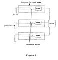
- FIG. 1 shows one known vacuum-based system, in which each pickline is connected to an individual pump, and each of the pumps is connected to a single AC motor. Associated with each pickline is a solenoid valve for opening or closing the line so that air can be selectively evacuated thereform. Also associated with each line is gearing or other mechanical means (not shown) for moving the end of the pickline into contact with the banknote, and then towards a dispensing location. This gearing is powered by the AC motor.
- FIG. 2 shows another known arrangement.
- a single pump driven by a single motor is used to create a pressure difference in a selected one of the pick-up lines and drive a gearing mechanism for moving the pickline between pick-up and release positions.
- Each of the picklines is provided as a separate branch of a single line that is connected directly to the pump.
- a solenoid valve Provided in each pickline is a solenoid valve. By selectively opening and closing the solenoid valves as appropriate, a selected one of the picklines can be exposed to the pump and so used for a pick and place action.
- the motor is switched on to power the pump. Because the motor also powers the gearing, this means that all of the gearing is caused to move.
- the pump is running, one of the valves is opened so that air is drawn through the associated pickline and the suction cap on the line is moved towards the banknote until it is moved into contact therewith, and removed as described previously.
- An object of the present invention is to provide an improved mechanism for dispensing banknotes from a self-service terminal.
- a self-service machine such as an automated teller machine, that includes a plurality of valveless vacuum pick mechanisms for picking media, such as banknotes, each valveless vacuum pick mechanism including a pump, a pickline connected the pump, a drive mechanism for moving at least a portion of the pickline between a media pick position and a media release position, and a motor for driving both the pump and the drive mechanism.
- each of the plurality of vacuum pick mechanisms By providing each of the plurality of vacuum pick mechanisms with an individual pump and a separate motor, the need for valves can be avoided, and wear on the drive system can be reduced.
- the pump may be a single stroke pump, preferably a synchronous stroke pump.
- the drive mechanism may be operable to move the pickline and a piston of the stroke pump.
- the drive mechanism may be operable to move the pickline between a media pick position and a media release position and back again in a single pump stroke cycle.
- the motor may be a stepper motor.
- a valveless vacuum pick mechanism for picking media such as banknotes, including a pump, a valveless pickline connected to the pump, a drive mechanism for moving the pickline between a media pick position and a media release position, and a motor for driving both the pump and the drive mechanism.
- the pump may be a single stroke pump, preferably a synchronous stroke pump.
- the drive mechanism may operable to move the pickline and a piston of the stroke pump.
- the drive mechanism may be operable to move the pickline between the media pick and release positions and back again in a single pump stroke cycle.
- the motor may be a stepper motor.
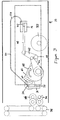
- FIGS 3 to 6 show a vacuum pick mechanism 10 for picking a banknote 12 individually from a bundle 14 of such notes in a dispensing cassette 16 and forwarding that note 12 to another part of the dispenser.
- a vacuum pick mechanism 10 for picking a banknote 12 individually from a bundle 14 of such notes in a dispensing cassette 16 and forwarding that note 12 to another part of the dispenser.
- a single mechanism 10 is shown. However, it will be appreciated that in, for example, an ATM environment, a plurality of these would be stacked on top of each other.
- the vacuum pick mechanism 10 of Figures 3 to 6 is carried on a support or housing of a cash dispensing cassette 16. It includes a single stroke pump 18, the output of which is connected directly to a pickline 20 that has a flexible tube portion 22 and a rotatable, rigid tube 24 that carries two downwardly extending pick-up members 26 (only one shown) at the ends of which are provided suction cups 28. Formed through the rigid tube 24 and each of the pick up members 26 are channels that open into the suction cups 28, so that a clear, valveless fluid flow path is provided between the pump 18 and the suction cups 28. As can be seen most clearly in Figure 4, the rigid tube 24 is positioned substantially parallel to the dispensing end of the cassette 16, so that in use both the suction cups 28 can be moved into contact with a front one of the notes in the cassette 16.
- a gear 30 of a drive mechanism To move the suction cups 28 between a pick position and a release position, connected to one end of the rigid tube 24 is a gear 30 of a drive mechanism.
- This drive mechanism is also connected to the piston 32 of the single stroke pump 18 and is powered by a stepper motor 33.
- the drive mechanism is operable to move the piston 32 of the pump 18 and at the same time cause the rigid tube 24 to move the suction cups 28 close to or into engagement with a banknote in the dispensing cassette 16. Stroking of the piston 32 creates enough of a pressure difference to cause the banknote 12 to stick to the cups 28.
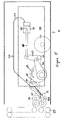
- continued action of the drive causes movement of the suction cups 28 and the note 12 away from the pick position towards a release position, in which the note 12 can be caught in take-away pinch rollers 34, 36 of a dispensing mechanism.
- the pinch rollers 34,36 of the dispensing mechanism are driven by the stepper motor 33, so that they can be moved between a rest position and a gripping position in an appropriate sequence timed to correspond with the movement of the suction caps 28 between the pick up and release positions.
- one of the pinch rollers 34 has a D-shaped cross section and the other 36 has a circular cross-section.
- the motor 33 is switched on initially, the D-shaped roller 34 is located half a turn away from a gripping position in which it co-operates with the other roller 36 to grip the banknote. Rotation of the semi-circular roller 34 by substantially half a turn is timed to correspond with movement of the banknote 12 into the area between the rollers 34 and 36, so that it can be gripped therebetween, as shown in Figure 6.
- the timing of the drive mechanism is such that when the banknote 12 is gripped by the rollers 34 and 36, the return stroke of the piston 32 starts. This allows the pressure difference between the pickline 20 and ambient to be gradually reduced, which in turn reduces the hold on the note 12. This allows the note 12 to be removed from the cups 28 by the rollers 34 and 36.
- Continued movement of the drive rotates the semi-circular roller 34 by another half turn thereby to pass the note 12 onto the next stage of the dispensing mechanism, typically a vertical transport system 38, and return the D-shaped roller 34 to its starting position. At the same time, this continued movement of the drive returns the suction cups 28 and the pump piston 32 to their starting positions. In this way, with each cycle of the piston 32, a single note 12 can be picked from the cassette 16, and moved to the transport mechanism 38, and the drive, piston 32 and dispensing gear 34 and 36 can be returned to positions ready for re-use.
- This includes a pickline drive segment 40 for moving the rigid pickline tube 24, and so the suction cups 28, a pump rod arrangement 42, 44 and 46 for driving the piston 32 of the pump 18 and a cluster cam 48 for driving each of the pickline drive segment 40 and the pump rod arrangement 42, 44 and 46.
- Figures 7 and 8 shows various views of the cluster cam 48.
- This includes a pickline cam 50, a circular drive gear 52 and a pump drive cam 54.
- Typically all parts of the cluster cam 48 are integrally formed.
- Defined through the centre of the cluster 48 and concentric with the drive gear 52 is a hole 56 for receiving a shaft, about which the cluster cam 48 can be driven by engagement of the drive gear 52 with a corresponding gear mechanism (not shown) driven by the stepper motor 33.
- a corresponding gear mechanism not shown
- any other suitable arrangement for coupling to the motor 33 could be used.
- Figures 7(a) and 8(a) show the pickline cam 50.
- This has a smooth edged triangular shape defined by an external ridge 58, and is positioned so that one of its smooth corners protrudes beyond the edge of the circular drive gear 52.
- Formed inwardly of the external ridge 58 is a correspondingly shaped internal ridge 60, the internal and external ridges defining a cam track 62 between them.
- the cam track 62 is shaped and sized to receive a roller 64 that projects from a surface of the pickline drive arm 40, as shown in Figure 9.
- This arm 40 is pivoted co-axially with one end of the pump crank arm 42 that is connected at its other end by a rod 44 to one end of the piston 32 of the pump 18.
- a gear 66 for meshing with the gear 30 carried on the rigid tube 24 of the pickline 20.
- One cycle of rotation of the cluster cam 48 by the motor 33 causes movement of the arm gear 40 into engagement with the gear 30 on the rigid tube 24 and so rotation of the suction caps 28 away from the pick up position and towards the release position. Continued rotation of the cam 48 causes the suction pads 28 to be rotated back to their starting position.
- FIGS 7(b) and 8(b) show the eccentric pump drive cam 54.
- This has a circular cross-section and is positioned offset relative to the centre of the cluster 48.
- Pivotally mounted on the pump cam 54 is a drive rod 46 that is fixedly connected at its other end to the pump crank arm 42, at a position above and offset from the common pivot point 68 with the pickline arm 40.
- Rotation of the cam cluster 48 causes the end of the pump drive arm 40 to follow an eccentric revolution path, which in conjunction with the action of the pump crank arm 42, causes the pump piston 32 to be moved rearwardly and then returned to a starting position in a single cycle of the cluster 48.
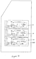
- the vacuum pick mechanism in which the invention is embodied is simple and effective. Also, because each mechanism in a stack can be independently constructed, it allows a modular approach to building ATMs or other self-service terminals, as shown in Figure 10. By avoiding the need for valves, control and timing of the drive and pump can be done mechanically, which simplifies the process and makes it more reliable. Furthermore, the overall design reduces the number of components needed, which is advantageous in an ATM environment where space is generally very restricted.
Landscapes
- Physics & Mathematics (AREA)
- General Physics & Mathematics (AREA)
- Engineering & Computer Science (AREA)
- Mechanical Engineering (AREA)
- Sheets, Magazines, And Separation Thereof (AREA)
Applications Claiming Priority (2)
| Application Number | Priority Date | Filing Date | Title |
|---|---|---|---|
| GBGB0328961.8A GB0328961D0 (en) | 2003-12-13 | 2003-12-13 | Vacuum picking system |
| GB0328961 | 2003-12-13 |
Publications (1)
| Publication Number | Publication Date |
|---|---|
| EP1541509A1 true EP1541509A1 (de) | 2005-06-15 |
Family
ID=30130201
Family Applications (1)
| Application Number | Title | Priority Date | Filing Date |
|---|---|---|---|
| EP04256797A Withdrawn EP1541509A1 (de) | 2003-12-13 | 2004-11-03 | Entnahmesystem mit Saugluft |
Country Status (3)
| Country | Link |
|---|---|
| US (1) | US7232059B2 (de) |
| EP (1) | EP1541509A1 (de) |
| GB (1) | GB0328961D0 (de) |
Families Citing this family (19)
| Publication number | Priority date | Publication date | Assignee | Title |
|---|---|---|---|---|
| US20070205260A1 (en) * | 2005-12-16 | 2007-09-06 | Ncr Corporation | Media pick unit |
| US7641185B2 (en) * | 2005-12-22 | 2010-01-05 | Ncr Corporation | Vacuum pick mechanisms |
| US9146564B2 (en) | 2006-03-06 | 2015-09-29 | Deka Products Limited Partnership | Product dispensing system |
| US11906988B2 (en) | 2006-03-06 | 2024-02-20 | Deka Products Limited Partnership | Product dispensing system |
| US8322570B2 (en) * | 2007-09-06 | 2012-12-04 | Deka Products Limited Partnership | Product dispensing system |
| JP5439376B2 (ja) * | 2007-09-06 | 2014-03-12 | デカ・プロダクツ・リミテッド・パートナーシップ | Rfidシステム及びその使用方法 |
| US12135019B2 (en) | 2007-09-06 | 2024-11-05 | Deka Products Limited Partnership | Product dispensing system |
| BRPI0817076A2 (pt) | 2007-09-06 | 2015-03-24 | Deka Products Lp | Sistema e método de processamento |
| US10562757B2 (en) | 2007-09-06 | 2020-02-18 | Deka Products Limited Partnership | Product dispensing system |
| US11634311B2 (en) | 2007-09-06 | 2023-04-25 | Deka Products Limited Partnership | Product dispensing system |
| US9270010B2 (en) * | 2007-09-06 | 2016-02-23 | Deka Products Limited Partnership | RFID system with an eddy current trap |
| US10859072B2 (en) | 2007-09-06 | 2020-12-08 | Deka Products Limited Partnership | Product dispensing system |
| US8314740B2 (en) | 2007-09-06 | 2012-11-20 | Deka Products Limited Partnership | RFID system |
| WO2009143289A2 (en) | 2008-05-20 | 2009-11-26 | Deka Products Limited Partnership | Rfid system |
| CN104310298B (zh) | 2008-08-28 | 2017-05-10 | 德卡产品有限公司 | 产品配制系统 |
| US8727336B2 (en) * | 2011-10-31 | 2014-05-20 | Ncr Corporation | Condition determining |
| US11135345B2 (en) | 2017-05-10 | 2021-10-05 | Fresenius Medical Care Holdings, Inc. | On demand dialysate mixing using concentrates |
| EP3467245B1 (de) * | 2017-10-09 | 2023-01-25 | Peter Villiger | Sicherheitskassette, gesamtvorrichtung mit einer sicherheitskassette und verfahren zum handhaben von wertscheinen |
| US11504458B2 (en) | 2018-10-17 | 2022-11-22 | Fresenius Medical Care Holdings, Inc. | Ultrasonic authentication for dialysis |
Citations (6)
| Publication number | Priority date | Publication date | Assignee | Title |
|---|---|---|---|---|
| US4065118A (en) * | 1972-11-29 | 1977-12-27 | Dudley George M | Mono-page paper distributor |
| US4494743A (en) * | 1981-08-31 | 1985-01-22 | Docutel Corporation | Dispenser picker apparatus |
| US4591140A (en) * | 1983-03-12 | 1986-05-27 | Agfa-Gevaert Aktiengesellschaft | Arrangement for separating and transporting uppermost sheets of a stack of sheets or sheet-like objects |
| JPH1077130A (ja) * | 1996-09-04 | 1998-03-24 | Canon Inc | シート給送装置及び画像形成装置 |
| EP0851394A1 (de) * | 1996-12-18 | 1998-07-01 | NCR International, Inc. | Geldgerät |
| WO2002028754A1 (en) * | 2000-10-05 | 2002-04-11 | De La Rue International Limited | Document feed assembly |
Family Cites Families (2)
| Publication number | Priority date | Publication date | Assignee | Title |
|---|---|---|---|---|
| GB9414540D0 (en) * | 1994-07-19 | 1994-09-07 | At & T Global Inf Solution | Apparatus for assessing the condition of a bank note |
| GB9623289D0 (en) * | 1996-11-08 | 1997-01-08 | Ncr Int Inc | Sheet handling apparatus |
-
2003
- 2003-12-13 GB GBGB0328961.8A patent/GB0328961D0/en not_active Ceased
-
2004
- 2004-11-03 EP EP04256797A patent/EP1541509A1/de not_active Withdrawn
- 2004-12-08 US US11/006,961 patent/US7232059B2/en not_active Expired - Lifetime
Patent Citations (6)
| Publication number | Priority date | Publication date | Assignee | Title |
|---|---|---|---|---|
| US4065118A (en) * | 1972-11-29 | 1977-12-27 | Dudley George M | Mono-page paper distributor |
| US4494743A (en) * | 1981-08-31 | 1985-01-22 | Docutel Corporation | Dispenser picker apparatus |
| US4591140A (en) * | 1983-03-12 | 1986-05-27 | Agfa-Gevaert Aktiengesellschaft | Arrangement for separating and transporting uppermost sheets of a stack of sheets or sheet-like objects |
| JPH1077130A (ja) * | 1996-09-04 | 1998-03-24 | Canon Inc | シート給送装置及び画像形成装置 |
| EP0851394A1 (de) * | 1996-12-18 | 1998-07-01 | NCR International, Inc. | Geldgerät |
| WO2002028754A1 (en) * | 2000-10-05 | 2002-04-11 | De La Rue International Limited | Document feed assembly |
Non-Patent Citations (1)
| Title |
|---|
| PATENT ABSTRACTS OF JAPAN vol. 1998, no. 08 30 June 1998 (1998-06-30) * |
Also Published As
| Publication number | Publication date |
|---|---|
| GB0328961D0 (en) | 2004-01-14 |
| US7232059B2 (en) | 2007-06-19 |
| US20050127162A1 (en) | 2005-06-16 |
Similar Documents
| Publication | Publication Date | Title |
|---|---|---|
| US7232059B2 (en) | Vacuum picking system | |
| US6698749B2 (en) | Device for feeding folded or unfolded signatures to a production line | |
| US5719383A (en) | Transaction terminal and method of maintaining acceptable operation of the transaction terminal | |
| CN103177504B (zh) | 纸币处理设备及其循环钞箱机构 | |
| US8511666B2 (en) | Paper sheets storage and paper sheets handling apparatus | |
| US10106358B2 (en) | Paper money stacking apparatus and paper money processing device | |
| CN102063760A (zh) | 可切换式钞票拾取装置 | |
| CN102007059A (zh) | 控制矩形单张纸,特别是纸币,分别输入至容器中和从容器中输出的单张纸处理设备 | |
| EP0675465A1 (de) | Einrichtung zum Speichern von Blättern und Transaktionseinrichtung | |
| JPS6311263B2 (de) | ||
| US4533824A (en) | Automatic depositing/dispensing apparatus | |
| GB2122010A (en) | Automatic depositing/ dispensing apparatus | |
| CA1281042C (en) | Sheet separating apparatus | |
| GB2122008A (en) | Automatic depositing/dispensing apparatus | |
| JP2000506298A (ja) | 現金自動支払機 | |
| CN112562218B (zh) | 一种票据自助回收与发放一体化的智能处理装置 | |
| CN1854039B (zh) | 用于从现金交易机中提款的设备 | |
| WO2007068888A1 (en) | Media pick unit | |
| JPH09151009A (ja) | 紙幣収納装置 | |
| JP2500766Y2 (ja) | 紙幣収納装置 | |
| JP4161233B2 (ja) | 紙幣処理装置 | |
| EP1798694A2 (de) | Entnahmemechanismus | |
| CN113920641B (zh) | 具有纸币单张回收功能的取款出钞装置及自动取款机 | |
| JP3552819B2 (ja) | 紙幣収納庫 | |
| JPH0444791B2 (de) |
Legal Events
| Date | Code | Title | Description |
|---|---|---|---|
| PUAI | Public reference made under article 153(3) epc to a published international application that has entered the european phase |
Free format text: ORIGINAL CODE: 0009012 |
|
| AK | Designated contracting states |
Kind code of ref document: A1 Designated state(s): AT BE BG CH CY CZ DE DK EE ES FI FR GB GR HU IE IS IT LI LU MC NL PL PT RO SE SI SK TR |
|
| AX | Request for extension of the european patent |
Extension state: AL HR LT LV MK YU |
|
| 17P | Request for examination filed |
Effective date: 20051215 |
|
| AKX | Designation fees paid |
Designated state(s): DE ES FR GB IT |
|
| 17Q | First examination report despatched |
Effective date: 20070529 |
|
| STAA | Information on the status of an ep patent application or granted ep patent |
Free format text: STATUS: THE APPLICATION HAS BEEN WITHDRAWN |
|
| 18W | Application withdrawn |
Effective date: 20071001 |