EP1541252A1 - Tuyau en acier uoe presentant une excellente resistance aux impacts, et procede de fabrication du tuyau en acier uoe - Google Patents
Tuyau en acier uoe presentant une excellente resistance aux impacts, et procede de fabrication du tuyau en acier uoe Download PDFInfo
- Publication number
- EP1541252A1 EP1541252A1 EP03733045A EP03733045A EP1541252A1 EP 1541252 A1 EP1541252 A1 EP 1541252A1 EP 03733045 A EP03733045 A EP 03733045A EP 03733045 A EP03733045 A EP 03733045A EP 1541252 A1 EP1541252 A1 EP 1541252A1
- Authority
- EP
- European Patent Office
- Prior art keywords
- steel pipe
- less
- uoe
- ing
- strength
- Prior art date
- Legal status (The legal status is an assumption and is not a legal conclusion. Google has not performed a legal analysis and makes no representation as to the accuracy of the status listed.)
- Granted
Links
Images


Classifications
-
- C—CHEMISTRY; METALLURGY
- C22—METALLURGY; FERROUS OR NON-FERROUS ALLOYS; TREATMENT OF ALLOYS OR NON-FERROUS METALS
- C22C—ALLOYS
- C22C38/00—Ferrous alloys, e.g. steel alloys
- C22C38/02—Ferrous alloys, e.g. steel alloys containing silicon
-
- B—PERFORMING OPERATIONS; TRANSPORTING
- B21—MECHANICAL METAL-WORKING WITHOUT ESSENTIALLY REMOVING MATERIAL; PUNCHING METAL
- B21C—MANUFACTURE OF METAL SHEETS, WIRE, RODS, TUBES OR PROFILES, OTHERWISE THAN BY ROLLING; AUXILIARY OPERATIONS USED IN CONNECTION WITH METAL-WORKING WITHOUT ESSENTIALLY REMOVING MATERIAL
- B21C37/00—Manufacture of metal sheets, bars, wire, tubes or like semi-manufactured products, not otherwise provided for; Manufacture of tubes of special shape
- B21C37/06—Manufacture of metal sheets, bars, wire, tubes or like semi-manufactured products, not otherwise provided for; Manufacture of tubes of special shape of tubes or metal hoses; Combined procedures for making tubes, e.g. for making multi-wall tubes
- B21C37/065—Manufacture of metal sheets, bars, wire, tubes or like semi-manufactured products, not otherwise provided for; Manufacture of tubes of special shape of tubes or metal hoses; Combined procedures for making tubes, e.g. for making multi-wall tubes starting from a specific blank, e.g. tailored blank
-
- B—PERFORMING OPERATIONS; TRANSPORTING
- B21—MECHANICAL METAL-WORKING WITHOUT ESSENTIALLY REMOVING MATERIAL; PUNCHING METAL
- B21C—MANUFACTURE OF METAL SHEETS, WIRE, RODS, TUBES OR PROFILES, OTHERWISE THAN BY ROLLING; AUXILIARY OPERATIONS USED IN CONNECTION WITH METAL-WORKING WITHOUT ESSENTIALLY REMOVING MATERIAL
- B21C37/00—Manufacture of metal sheets, bars, wire, tubes or like semi-manufactured products, not otherwise provided for; Manufacture of tubes of special shape
- B21C37/06—Manufacture of metal sheets, bars, wire, tubes or like semi-manufactured products, not otherwise provided for; Manufacture of tubes of special shape of tubes or metal hoses; Combined procedures for making tubes, e.g. for making multi-wall tubes
- B21C37/08—Making tubes with welded or soldered seams
- B21C37/0822—Guiding or aligning the edges of the bent sheet
-
- B—PERFORMING OPERATIONS; TRANSPORTING
- B21—MECHANICAL METAL-WORKING WITHOUT ESSENTIALLY REMOVING MATERIAL; PUNCHING METAL
- B21C—MANUFACTURE OF METAL SHEETS, WIRE, RODS, TUBES OR PROFILES, OTHERWISE THAN BY ROLLING; AUXILIARY OPERATIONS USED IN CONNECTION WITH METAL-WORKING WITHOUT ESSENTIALLY REMOVING MATERIAL
- B21C37/00—Manufacture of metal sheets, bars, wire, tubes or like semi-manufactured products, not otherwise provided for; Manufacture of tubes of special shape
- B21C37/06—Manufacture of metal sheets, bars, wire, tubes or like semi-manufactured products, not otherwise provided for; Manufacture of tubes of special shape of tubes or metal hoses; Combined procedures for making tubes, e.g. for making multi-wall tubes
- B21C37/08—Making tubes with welded or soldered seams
- B21C37/0826—Preparing the edges of the metal sheet with the aim of having some effect on the weld
-
- C—CHEMISTRY; METALLURGY
- C21—METALLURGY OF IRON
- C21D—MODIFYING THE PHYSICAL STRUCTURE OF FERROUS METALS; GENERAL DEVICES FOR HEAT TREATMENT OF FERROUS OR NON-FERROUS METALS OR ALLOYS; MAKING METAL MALLEABLE, e.g. BY DECARBURISATION OR TEMPERING
- C21D9/00—Heat treatment, e.g. annealing, hardening, quenching or tempering, adapted for particular articles; Furnaces therefor
- C21D9/08—Heat treatment, e.g. annealing, hardening, quenching or tempering, adapted for particular articles; Furnaces therefor for tubular bodies or pipes
-
- C—CHEMISTRY; METALLURGY
- C21—METALLURGY OF IRON
- C21D—MODIFYING THE PHYSICAL STRUCTURE OF FERROUS METALS; GENERAL DEVICES FOR HEAT TREATMENT OF FERROUS OR NON-FERROUS METALS OR ALLOYS; MAKING METAL MALLEABLE, e.g. BY DECARBURISATION OR TEMPERING
- C21D9/00—Heat treatment, e.g. annealing, hardening, quenching or tempering, adapted for particular articles; Furnaces therefor
- C21D9/50—Heat treatment, e.g. annealing, hardening, quenching or tempering, adapted for particular articles; Furnaces therefor for welded joints
-
- C—CHEMISTRY; METALLURGY
- C22—METALLURGY; FERROUS OR NON-FERROUS ALLOYS; TREATMENT OF ALLOYS OR NON-FERROUS METALS
- C22C—ALLOYS
- C22C38/00—Ferrous alloys, e.g. steel alloys
- C22C38/04—Ferrous alloys, e.g. steel alloys containing manganese
-
- C—CHEMISTRY; METALLURGY
- C22—METALLURGY; FERROUS OR NON-FERROUS ALLOYS; TREATMENT OF ALLOYS OR NON-FERROUS METALS
- C22C—ALLOYS
- C22C38/00—Ferrous alloys, e.g. steel alloys
- C22C38/12—Ferrous alloys, e.g. steel alloys containing tungsten, tantalum, molybdenum, vanadium, or niobium
-
- C—CHEMISTRY; METALLURGY
- C22—METALLURGY; FERROUS OR NON-FERROUS ALLOYS; TREATMENT OF ALLOYS OR NON-FERROUS METALS
- C22C—ALLOYS
- C22C38/00—Ferrous alloys, e.g. steel alloys
- C22C38/14—Ferrous alloys, e.g. steel alloys containing titanium or zirconium
-
- Y—GENERAL TAGGING OF NEW TECHNOLOGICAL DEVELOPMENTS; GENERAL TAGGING OF CROSS-SECTIONAL TECHNOLOGIES SPANNING OVER SEVERAL SECTIONS OF THE IPC; TECHNICAL SUBJECTS COVERED BY FORMER USPC CROSS-REFERENCE ART COLLECTIONS [XRACs] AND DIGESTS
- Y10—TECHNICAL SUBJECTS COVERED BY FORMER USPC
- Y10T—TECHNICAL SUBJECTS COVERED BY FORMER US CLASSIFICATION
- Y10T29/00—Metal working
- Y10T29/18—Expanded metal making
Definitions
- the present invention relates to UOE steel pipe excellent in collapse characteristics formed by the UOE production method and a method for forming this UOE steel pipe.
- the process of production of steel pipe of the UOE process is comprised of a process of C-ing (pressing), U-ing (pressing), O-ing (pressing), seam welding, and expansion.
- the diameter is reduced by an O-mold. This is called “upset” of O-ing.
- expansion is a process of correcting the circularity by pushing outward from the inside by metal segments. Tensile stress in the circumferential direction is applied for plastic deformation.
- Japanese Unexamined Patent Publication (Kokai) No. 9-3545 discloses and reports numerous research papers. In these methods, the compression yield strength dropping due to forming is restored to the level of the plate material before forming and the collapse strength of UOE steel pipe is improved to a certain extent.
- the present invention has as its object to provide UOE steel pipe improved in collapse strength by heat treatment to leave work hardening obtained by cold working the inside surface side and to eliminate the Bauschinger effect from the outside surface to the center of thickness (hereinafter referred to as the "outside surface side").
- the present invention has as its object to provide UOE steel pipe improved in collapse strength by optimizing the UOE production process even without heat treatment.
- the inventors first engaged in detailed studies to clarify the changes in the collapse strength in the thickness direction of UOE steel pipe. As a result, they discovered that the compression yield strength at the outside surface side falls compared with steel plate before forming and rises at the inside surface side. From this discovery, they studied in detail a heat treatment method for improving the compression yield strength of the outside surface side to equal to that of steel plate and maintaining the compression yield strength at the inside surface side and suppressing the drop in strength in the axial direction by heat treatment making the outside surface a high temperature and the inside surface a low temperature. As a result, they discovered the optimal heat treatment conditions and succeeded in producing UOE steel pipe excellent in collapse strength.
- the inventors took note of the improvement in the collapse strength by giving compressive plastic strain from the inside surface of UOE steel pipe to the center of thickness (hereinafter referred to as the "inside surface side") and optimized the ratio of the upset rate at the time of O-ing and the expansion rate at the time of expansion to give compressive plastic strain to the inside surface side and keep the drop in the compression yield stress to a minimum.
- the compression strength of Nb-containing steel cooled after hot rolling to the low temperature region of 300°C or less is higher than steel plate air-cooled after hot rolling or steel plate water-cooled to 500 to 600°C and then stopped being cooled.
- the collapse strength is restored to at least the same level as before expansion. Further, they learned that this effect becomes more conspicuous by addition of Ti and that even if heating to a low temperature of 80 to less than 150°C, the Bauschinger effect is recovered from.
- the present invention was made based on this discovery and has as its gist the following:
- the inventors first examined a typical size of UOE steel pipe used for deep sea line pipe, that is, diameter 660 x 25.4 mm, X-65, for compressive stress-strain behavior in the circumferential direction over the entire cross-section. For test pieces, they obtained columnar shapes of diameters of 6 mm and lengths of 15 mm at 1/4 the total thickness from the outside surface, 1/4 the total thickness from the inside surface, and the center of thickness using the circumferential direction as longitudinal.
- FIG. 4 plots the rate of change of the compression yield strength with respect to the positions of obtaining the test pieces in the thickness direction.
- the rate of change of the compression yield strength is the percentage obtaining by subtracting the compression strength of the steel plate before forming from the compression yield strength of the steel pipe and dividing the result by the compression strength of the steel plate before forming. From this, they learned that at the outside surface side, the compression yield strength falls by at least about 20% with respect to the steel plate before forming, but conversely rises at the inner surface side.
- the heating temperature T 1 of the outside surface is preferably set to an upper limit of not more 700°C so as not to allow phase transformation or other structural changes.
- the upper limit of time is preferably set to not more than 6000 seconds if considering the productivity.
- the heating temperature T 2 of the inside surface is preferably as low as possible, but in practice, due to heat conduction from the outside surface, the lower limit becomes about 100°C. Further, the lower limit of the heating time t 2 of the inside surface is not defined. It is also possible to immediately cool after reaching the heating temperature T 2 .
- the upper limit depends on the heat conduction from the outside surface, so is not defined.
- the rate of drop in the compression yield strength at the outer surface side due to the Bauschinger effect does not depend on the magnitude of the tension strain due to the bending at the time of pipe production changing due to the magnitude of the tensile strain at the time of expansion and the thickness.
- the rise in the compression yield strength at the inner surface side depends on the degree of the work hardening changing depending on the magnitude of the compression strain at the time of O-ing and the thickness. Therefore, the greater the thickness, the more the compression yield strength of the outer surface side does not change and the larger the compression yield strength at the inner surface side, so in deep sea line pipe steel pipe with a thickness of 25 to 40 mm or so, the effect of the present invention becomes extremely conspicuous.
- the mode of collapse can be differentiated by the outside diameter/thickness ratio.
- elastic collapse where the collapse strength is not dependent on the compression yield strength is exhibited.
- the thinner the more the trend toward transition collapse, plastic collapse, and yield collapse dependent on the compression yield strength.
- the general size of line pipe is relatively thin, so is in the elastic collapse region, but the size applied to deep seas is thick, so the compression yield strength starts to be strongly affected. Therefore, maintenance of the compression yield strength of the inner surface side and recovery of the compression strength at the outer surface side due to the heat treatment of the present invention are effectively exhibited.
- the method of heating the outside surface by induction heating is extremely effective. It is possible to easily give a sharp temperature distribution to the inner and outer surfaces in a short time.
- the temperature distribution may be obtained by suitably optimizing the depth of penetration of the induction heating and the steel pipe conveyance speed in relation to the thickness.
- the method for obtaining the temperature distribution of the present invention may be realized by heating in an oil tank or salt bath or other atmosphere with a large coefficient of heat conduction from the outside surface or by forced cooling from the inside surface.
- the corrosion resistance is mainly improved by coating the outside surface of the steel pipe with plastic.
- This plastic or other coating has to be applied at a temperature of about 150 to 250°C to raise the bonding strength.
- the temperature difference between the inside surface and outside surface is large, so the drop in the outside surface temperature due to heat conduction in the thickness direction is fast and the suitable temperature for coating is reached in a short time. Due to this, the number of coatings per time increases, the collapse strength is improved, and production cost can be slashed.
- the inside surface temperature may exceed the temperature-time conditions of the inside surface defined by the present invention.
- the temperature range of the inside surface of the present invention is possible in terms of heat conduction when holding the outside surface in the temperature range of the present invention and is defined to the range where the work hardening of the inside surface side is not lost. Therefore, even if the scope of the present invention is not satisfied due to the relationship between the temperature-time of the outside surface and inside surface at the time of coating not being possible in terms of heat conduction, the relationship between the temperature-time at the time of heat treatment is included in the present invention if formula (1) and formula (2) are satisfied.
- the compression yield strength at the inner surface is maintained at 1.05 times or more the tension yield strength and the compression yield strength of the outer surface recovers to at least 90% of the tension yield strength.
- the inventors examined in detail the compression yield strength in the circumferential direction from the outside surface of the steel plate to the center of thickness (hereinafter referred to as the "outside surface side") at the cross-section of steel pipe produced by the UOE process while changing the position of taking the test pieces in the circumferential direction.
- the test pieces were made columnar shapes of diameters of 6 mm and lengths of 15 mm with the circumferential directions as longitudinal.
- the results are shown in FIG. 9, where the abscissa indicates the counterclockwise angle from the axially symmetric part of the seam weld of the steel pipe as 0°.
- the seam weld was 180°.
- the rate of maintenance of the compression yield strength of the ordinate is the percent of the compression yield strength of the steel pipe divided by the compression strength of the steel plate before forming.
- the inventors took note of the possibility of being able to suppress the drop in the compression yield stress at the outside surface side by controlling the balance between the compressive plastic strain at the time of upset in O-ing and the tensile plastic strain at the time of expansion.
- the Bauschinger effect is the phenomenon of the yield strength dropping in the opposite direction to the plastic strain, so the inventors tried to suppress the drop in the compression yield stress at the outside surface side by increasing the upset rate to apply more compressive plastic strain and reducing the expansion rate to reduce the tensile prestraining.
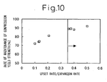
- the test was conducted by producing steel pipe with an outside diameter/thickness of 18.7 while changing the ratio of the upset rate ⁇ and the expansion rate ⁇ at the time of O-ing and obtaining compression test pieces centered at 1/4 of the total thickness from the outside surface of the axially symmetric part from the weld.
- the results are shown in FIG. 10 as the change of the rate of maintenance of the compression yield strength with respect to ⁇ / ⁇ .
- the upset rate and the expansion rate are based on the following definitions.
- the inventors clarified that by setting ⁇ / ⁇ 0.35, the rate of maintenance of the compression yield strength reaches 90% and thereby set the lower limit of ⁇ / ⁇ to 0.35.
- the upper limit of ⁇ / ⁇ depends on the preferable range and optimal range of the upper limit of ⁇ and the lower limit of ⁇ explained later.
- the preferable range is not more than 1, while the optimal range is not more than 0.6.
- the lower limit of ⁇ is preferably at least 0.3% from the minimization of the seam gap before welding and reduction of peaking of the welds as shown in FIG. 13 and FIG. 14.
- the upper limit of ⁇ the higher, the more easily the reduction in the compression yield strength can be inhibited, but at the time of O-ing, overlap or buckling of the beveling such as shown in FIG.
- FIG. 11 shows the difference in the compression/tension yield ratio at the outer surface and inner surface of the steel pipe.
- the compression yield strength of the inner surface was maintained at 1.1 times the tension yield strength or more, while the compression yield strength of the outer surface became at least 90% the tension yield strength. Note that the method of measurement of FIG. 11 will be explained in Example 2.
- the inventors examined in detail the relationship between the heating temperature and chemical composition and structure of steel relating to the phenomenon of the yield strength falling due to the Bauschinger effect being restored due to heat treatment.
- the inventors examined the microstructure of steel coiled at this 300°C or less and as a result found that this steel has a structure including upper bainite and other low temperature transformation phases. Such low temperature transformation phases are considered to suppress the drop in the compression yield strength due to the Bauschinger effect. Further, the reasons why the compression yield stress after expansion rises to equal or better than the compression yield strength before expansion are believed to be because the site of stress around dislocation causing the Bauschinger effect easily changes and C and other elements present in solute state fix firmly to dislocation.
- the inventors analyzed the precipitate in detail and as a result learned that fine TiN precipitates in Ti-containing steel. It is considered that due to the fine TiN, the coarsening of the austenite grains at the time of slab reheating and at the HAZ is suppressed and that the microstructure of the base material and HAZ becomes finer. As a result of such a uniform, fine microstructure being obtained, they discovered that the nonuniformity of the stress in the grains is mitigated, the residual stress easily becomes uniform, and the collapse strength falling due to the Bauschinger effect is easily improved by low temperature heat treatment due to the synergistic effect with the addition of Nb.
- the inventors made the steel plate produced in this way into steel pipe by the UOE process and examined in detail the drop in the compression yield strength due to the Bauschinger effect in the thickness direction from the outside surface side of the steel pipe to the inside surface side. As a result, they learned that the outside surface side receives the tensile strain in the circumferential direction in the process for forming into a cylindrical shape and the process of expansion, that due to the Bauschinger effect, the compression yield strength falls, that at the inner surface side, work hardening of compression due to bending in the UO process remains even after expansion, and the compression yield strength does not fall.
- the inventors studied the effect of heating on the drop in the compression yield strength due to the Bauschinger effect at the surface layer, center of thickness, and 1/4 thickness of the thickness direction from the outside surface side to the inside surface side of the steel pipe. As a result, they learned that the effect of heating the inside surface side is small, but that heating the outside surface side improves the collapse strength. This heating is effective in the range of 80 to 550°C. Further, even in the range of 80 to 250°C, the effect is large. An effect was also recognized at a low temperature of 80 to less than 150°C.
- the amount of C is limited to 0.03 to 0.15%. Carbon is extremely effective in improving the strength of steel. To obtain the target strength, a minimum of 0.03% is required. However, if the amount of C is greater than 0.15%, a remarkable deterioration in the low temperature toughness or on-site weldability of the HAZ of the base material is invited, so the upper limit was made 0.15%. The elongation becomes higher the greater the amount of C, while the low temperature toughness and the weldability become better the smaller the amount of C. It is necessary to consider the balance by the level of the required characteristics.
- Si is an element added for deoxygenation or improvement of strength, but if added in an amount greater than 0.8%, the HAZ toughness and on-site weldability are remarkably deteriorated, so the upper limit of the amount of Si was made 0.8%. Note that deoxygenation of steel is possible by Al and Ti as well. Si does not necessarily have to be added, but usually is included in an amount of 0.1% or so.
- Mn is an element essential for making the microstructure of the base phase of the steel of the present invention a mainly bainite structure and securing a balance of excellent strength and low temperature toughness.
- the lower limit is 0.3%.
- the amount of Mn is greater than 2.5%, it becomes difficult for the ferrite to diffuse and be produced, so the upper limit was made 2.5%.
- the steel of the present invention contains as essential elements Nb: 0.01 to 0.3% and Ti: 0.005 to 0.03%.
- Nb not only suppresses recrystallization of austenite to make the structure finer at the time of controlled rolling, but also contributes to an increase of the quenchability and toughens the steel.
- the effect is small if the amount of Nb is less than 0.01%, so this is made the lower limit. However, if the amount of Nb added is greater than 0.3%, the HAZ toughness and the on-site weldability are adversely affected, so the upper limit was made 0.3%.
- the addition of Ti forms fine TiN and makes the microstructure of the base material and HAZ finer and promotes the effect of improvement of the collapse strength falling due to the Bauschinger effect by heating to 80 to 550°C, in particular 80 to less than 150°C. Further, it improves the low temperature toughness of the base material and HAZ. This effect becomes extremely remarkable due to the composite addition with Nb.
- the amount of Ti is preferably added in an amount of 3.4N (all wt%) or more. Further, when the amount of Al is small (for example, 0.005% or less), Ti forms an oxide, acts as a ferrite forming nucleus in grains in the HAZ, and makes the HAZ structure finer in effect.
- Al is an element usually included in steel as a deoxygenating material and has the effect of making the structure finer as well. However, if the amount of Al is over 0.1%, the Al-based nonmetallic inclusions increase and detract from the cleanliness of the steel, so the upper limit was made 0.1%. Further, deoxygenation is also possible with Ti and Si, so Al does not necessarily have to be added, but with current technology, 0.001% or so is included.
- N forms TiN, suppresses the coarsening of the austenite grains at the time of slab reheating and at the HAZ, and improves the low temperature toughness of the base material and HAZ.
- the minimum amount required for this is 0.001%.
- the amount of N becomes greater than 0.01%, the TiN increases too much and surface defects, deteriorated toughness, and other problems occur, so the upper limit has to be suppressed to 0.01%.
- the amounts of the impurity elements P and S are made 0.03% and 0.01% or less.
- the main reason is to further improve the low temperature toughness of the base material and HAZ.
- Reduction of the amount of P mitigates the center segregation of the continuously cast slab and prevents grain destruction to improve the low temperature toughness.
- reduction of the amount of S reduces the MnS drawn by hot rolling and improves the drawing toughness in effect. With both, the less the better, but this has to be determined by the balance of characteristics and cost.
- Normally P and S are contained in amounts of 0.001% or more and 0.0001% or more.
- the main object of adding these elements to the basic ingredients is to try to further improve the strength and toughness and increase the size of the steel material which can be produced without detracting from the excellent features of the steel of the present invention.
- the object of adding Ni is to improve the low carbon steel of the present invention without degrading the low temperature toughness or on-site weldability. Addition of at least 0.1% is preferable. Addition of Ni, compared with addition of Cr and Mo, seldom forms a hard structure harmful to low temperature toughness in a rolled structure, in particular the center segregation zone of a continuously cast slab. However, if the amount of Ni is more than 1%, this causes deterioration of not only the economy, but also the HAZ toughness and on-site weldability, so the upper limit was made 1%. Further, the addition of Ni is also effective for preventing Cu cracking at the time of continuous casting and hot rolling. In this case, Ni has to be added in an amount at least 1/3 of the amount of Cu.
- the reason for adding the Mo is to improve the quenchability of steel and obtain a high strength. Addition of at least 0.1% is preferable. Further, Mo is also effective in suppressing recrystallization of austenite at the time of controlled rolling together with Nb and in making the austenite structure finer. However, excessive addition of Mo over 0.6% causes deterioration of the HAZ toughness and on-site weldability and further makes dispersion and formation of ferrite difficult, so the upper limit was made 0.6%.
- Cr increases the strength of the base material and welded part, so is preferably added in an amount of 0.1% or more, but if adding over 1%, the HAZ toughness and the on-site weldability are remarkably deteriorated. Therefore, the upper limit of the amount of Cr was made 1%.
- Cu increases the strength of the welded part, so is preferably added in an amount of at least 0.1%, but if added more than 1%, the HAZ toughness and on-site weldability are remarkably deteriorated. Therefore, the upper limit of the amount of Cu was made 1%.
- V has substantially the same effect as Nb, but the effect is weak relative to Nb. Further, it has the effect of suppressing the softening of the weld.
- As the upper limit up to 0.3% is allowable from the viewpoint of the HAZ toughness and on-site weldability, but addition of 0.03 to 0.08% is particularly preferable.
- B is an element for raising the quenchability of the steel by addition of a very small amount. This effect is insufficient if the amount of B is less than 0.0003%, so the lower limit of the amount of B was made 0.0003%. On the other hand, if excessively adding B more than 0.003%, this promotes the formation of Fe 23 (C,B) 6 and other brittle grains and causes deterioration of the low temperature toughness, so the upper limit of the amount of B was made 0.003%.
- Ca and REM control the form of the sulfides (MnS) and improve the low temperature toughness.
- Mg forms finely dispersed oxides, suppresses the grain coarsening of the welding HAZ, and improves the low temperature toughness, so is preferably added in an amount of 0.0001% or more. However, if adding more than 0.006%, it forms coarse oxides and degrades the toughness, so 0.006% was made the upper limit.
- the steel is reheated to the austenite region before rolling heating. It is necessary to raise the temperature to the temperature at which Nb dissolves. This reheating is preferably in the range of 1050°C to 1250°C where Nb dissolves and the grains do not become coarse.
- finishing rolling is performed in the non-recrystallization temperature region of 900°C or less. This is to raise the low temperature toughness basically required for line pipe.
- the Ar 3 point is made the lower limit of the end temperature of the finishing rolling.
- the cumulative reduction rate of the finishing rolling is made 50% or more. This is so as to secure the low temperature toughness required for line pipe.
- the upper limit of the cumulative reduction rate of finishing rolling is determined by the ratio of the thickness at the time of recrystallization rolling end and the product plate thickness.
- the steel After finishing rolling, the steel is cooled from the temperature of the Ar 3 point or more to 300°C or less. This is so as to obtain a structure including upper bainite or another low temperature transformation phase and containing C or Nb in solid solution.
- the lower limit of the cooling end temperature is not particularly limited from the characteristics, but normally is in the range of 50 to 150°C.
- the cooling rate when cooling from a temperature of the Ar 3 point or more to 300°C or less is made 5 to 40°C/sec. This is so as to obtain a structure including upper bainite or another low temperature transformation phase and containing C or Nb in solid solution.
- the steel plate produced in this way is successively C-ed, U-ed, and O-ed to form it into a cylinder and is joined at the abutting parts. This is then welded, then expanded to improve the circularity.
- the heating temperature is made the range of 80 to 550°C, but the effect is large even in the range of 80 to 250°C. In particular, an effect is recognized even at a low temperature of 80 to less than 150°C. For the inside or outside surface side, there is almost no change with heating in this temperature region, so heating is not necessarily required.
- the holding time at the heating temperature at a high temperature, it is possible to cool immediately after the heat treatment temperature is reached, while at a low temperature, it is also possible to hold the temperature for 6000 seconds or less.
- the preferable range is 60 to 1800 seconds.
- induction heating to heat the outside surface
- an oil tank or salt bath may also be used.
- the collapse strength of UOE steel pipe produced in this way has to be at least equal to the collapse strength calculated from the compression strength of the thick plate after hot rolling.
- a ratio b/a of the collapse strength a [MPa] of the steel pipe produced by the UOE process and the collapse strength b [MPa] of the steel pipe after heating at least a range from the outside surface to the center of thickness to 80 to 550°C of 1.10 or more means equal or better to the collapse strength calculated from the compression strength of the thick plate after hot rolling.
- FIG. 12 shows the difference in the compression/tension yield ratio at the outer surface and inner surface of the steel pipe.
- the outer surface of the steel pipe may also be coated.
- this is mainly plastic coating, but to raise the bonding strength, this has to be performed at a temperature of 150 to 250°C or so. Even if heating at the time of this coating, the Bauschinger effect is recovered from, so the efficiency is extremely good.
- UOE steel pipe of grades of X-65, X80, and X100 and outside diameters and thicknesses in the ranges of 660 to 711 mm and 25 to 38 mm were produced by the method shown in FIG. 1. These were given heat treatment under the conditions shown in Table 1. Note that the temperatures of the outside surfaces and inside surfaces of the steel pipe were measured by thermocouples.
- the collapse strengths of these steel pipe were measured by a single-axis collapse test. The single-axis collapse test was conducted by placing steel pipe of a length of 5 m as a collapse test sample in a pressure vessel and applying water pressure so that axial force did not occur in the steel pipe.
- the yield stresses of compression and tension were measured for 1/4 the total thickness from the outside surface as the outer surface and for 1/4 the total thickness from the inside surface as the inner surface and the ratio of these was examined.
- the test pieces measured for compression yield stress at this time were columns of a diameter of 6 mm and a length of 15 mm, while the test pieces measured for tension yield stress were tension test pieces having columnar parallel parts of diameters of 6 mm and lengths of 15 mm together with this.
- the results are shown in Table 1 and FIG. 8.
- Production Nos. 1 to 6 and 9 to 12 were given heat treatment by induction heating, while Production Nos. 7 and 8 were given heat treatment combining ambient heating and forced cooling. When the heating temperature was 400°C or more, the rise in temperature was sharp, so the heat treatment time means the time the temperature was exceeded for the outer surface temperature and means the time when the temperature was in the temperature range of the maximum temperature -10°C for the inside surface temperature.
- Production Nos. 13, 15, 17, and 18 were not given heat treatment, so fell greatly in collapse strength compared with Production Nos. 1 to 3, 4 to 8, 9, and 10 of the same size and same grade and in the scope of the present invention. Further, Production No. 14 had heat treatment conditions of the inside surface outside the scope of the present invention, so it was learned that the collapse strength clearly fell from Production No. 1 in the scope of the present invention with an outside surface heated to the same temperature.
- Production No. 16 had heat treatment conditions of the outside surface and inside surface outside the scope of the present invention, so the collapse stress clearly fell from Production No. 6 inside the scope of the present invention with the outside surface heated up to the same temperature.
- Production No. 11 was UOE steel pipe of a grade of X-100 which was given heat treatment in the scope of the present invention. A high collapse strength was obtained as a result of the collapse test.
- FIG. 8 compares the ratio of the yield stress of compression and tension at the outer surface and inner surface.
- the square marks of Invention 1 are not differentiated as to particular example, but are data of the present invention of Table 1.
- the triangle marks are data of the comparative examples.
- the compression/tension yield ratio fell in the range of 90% to 100% at the outer surface and became 110% or more at the inner surface.
- the collapse strength became about 8 to 50% higher compared with the comparative examples obtained under similar production conditions.
- UOE steel pipe of grades of X-65 and X80 and outside diameters and thicknesses in the ranges of 660 to 711 mm and 25 to 38 mm were produced by the outside diameter/thickness ratio, upset rate, and expansion rate shown in Table 2.
- Compression test pieces of columnar shapes of diameters of 6 mm and lengths of 15 mm long in the circumferential direction were cut out from the steel pipe from 1/4 the total thickness from the outside surface and measured for the compression yield strength. The results are shown as the compression yield strength maintenance rate.
- Single-axis collapse tests were conducted and the collapse strength measured by placing steel pipe of lengths of 5 m as collapse test samples in a pressure vessel and applying water pressure so that axial force did not occur in the steel pipe.
- the yield stresses of compression and tension were measured for 1/4 the total thickness from the outside surface as the outer surface and for 1/4 the total thickness from the inside surface as the inner surface and the ratio of these was examined.
- the test pieces measured for compression yield stress at this time were columns of a diameter of 6 mm and a length of 15 mm, while the test pieces measured for tension yield stress were tension test pieces having columnar parallel parts of diameters of 6 mm and lengths of 15 mm together with this. The results are shown in Table 2 and FIG. 11.
- Production Nos. 1 to 4 had ratios of the upset rate and expansion rate in the scope of the present invention and had rates of maintenance of the compression yield strength larger than Production Nos. 14 to 17 with the same grades and outside diameter/thickness ratio and ⁇ / ⁇ ratios of less than 0.35. Further, collapse tests were conducted on steel pipe of Production Nos. 1, 2, and 14, whereupon the collapse strengths of Production Nos. 1 and 2 in the scope of the present invention were higher than Production No. 14 outside the scope of the present invention, so the effects of the present invention could be verified. Further, Production No. 5 had a larger steel pipe compression yield strength ratio with respect to the plate material yield strength than Production No. 18 of the same grade and outside diameter/thickness ratio and an ⁇ / ⁇ ratio of less than 0.35.
- FIG. 11 compares the ratio of the yield stress of compression and tension at the outer surface and inner surface.
- the square marks of Invention 2 are not differentiated as to particular example, but are data of the present invention of Table 2.
- the triangle marks are data of the comparative examples.
- the compression/tension yield ratio fell in the range of 90% to 100% at the outer surface and became 110% or more at the inner surface.
- the collapse strength became about 7 to 20% higher compared with the comparative examples obtained under similar production conditions.
- Steels having the chemical compositions shown in Table 3 were produced by a converter and continuously cast to steel slabs which were then hot rolled under the conditions shown in Table 4.
- the end temperature of the finishing rolling was at least the Ar 3 point in each case.
- These steel plates were successively C-ed, U-ed, and O-ed as they were.
- the ends of the thick steel plates were seam welded, then the pipes were expanded in an UOE process to obtain steel pipe of the production conditions, outside diameters, and thicknesses shown in Table 4.
- These steel pipe were heated by the moving heating system at a high frequency.
- the temperatures of the outside surfaces and inside surfaces of the steel pipe were measured by a thermocouple.
- the temperatures of the centers of thickness were calculated as the average values of the outside surface temperatures and the inside surface temperatures.
- the heating temperatures shown in Table 4 are the temperatures of the outermost surfaces, while the actual heating times were about 180 seconds.
- the temperatures of the inside surfaces were not particularly controlled, but were about 30°C lower than the outside surface temperatures. Therefore, the temperatures at the centers of thickness became about 15°C lower than the outside surface temperatures.
- the steel pipe produced in this way were cut to 5 m, the steel pipe were placed in reaction vessels, and water pressure was applied so that no axial force was generated at the steel pipe in a single-axis collapse test.
- the pressure when applying water pressure and when the water pressure began to fall sharply was made the collapse strength.
- the collapse strength a [MPa] up to production of these steel pipe, the collapse strength b [MPa] after heat treatment, and the ratio b/a of the two are shown in Table 4.
- the yield stresses of compression and tension were measured for 1/4 the total thickness from the outside surface as the outer surface and for 1/4 the total thickness from the inside surface as the inner surface and the ratio of these was examined.
- test pieces measured for compression yield stress at this time were columns of a diameter of 6 mm and a length of 15 mm, while the test pieces measured for tension yield stress were tension test pieces having columnar parallel parts of diameters of 6 mm and lengths of 15 mm together with this.
- the results are also inserted into Table 4 and shown in FIG. 12.
- Example 1 to 9 of the method of the present invention due to the heating, the collapse strength rose 18 to 29% and steel pipe of a high collapse strength were obtained. In particular, even if heating to a low temperature of less than 150°C, the collapse strength improved, while even if 150°C or more, as will be understood from a comparison with Examples 2 and 11, the steel produced by the method of production of the present invention rose in collapse strength more. In Examples 10 and 12, since the cooling stop temperature was high, with heating at 140°C, the collapse strength was not improved and the collapse strength was low. Example 11 had a high heating temperature of 300°C, but the cooling stop temperature was high, so the collapse strength was not improved. Example 14 did not include Nb-Ti, so had a chemical composition outside the present invention and therefore the collapse strength was not improved.
- FIG. 12 compares the ratio of the compression and tension yield stresses at the outer surface and inner surface.
- the square marks of Invention 3 are not differentiated as to particular example, but are data of the present invention of Table 4.
- the triangle marks are data of the comparative examples.
- the compression/tension yield ratio fell in the range of 90% to 100% at the outer surface and became 105% or more at the inner surface.
- the collapse strength was only improved about 3% in the comparative examples obtained under similar production conditions, but was improved 18 to 29% in the present invention.
- the present invention by specifying the ratio of the upset rate at the time of O-ing and the expansion rate at the time of expansion for steel pipe produced by the UOE process, it is possible to impart a high collapse resistance and possible to provide UOE steel pipe excellent in collapse strength at a low cost. Further, by imparting a different heat hysteresis to the outside surface and inside surface of steel pipe, it is possible to impart a higher collapse resistance to steel pipe produced by the UOE process and possible to provide UOE steel pipe excellent in collapse strength at a low cost. This enables use for line pipe etc. for transporting natural gas, crude oil, etc. even in environments in which high collapse strength is required such as the deep sea.
Landscapes
- Chemical & Material Sciences (AREA)
- Engineering & Computer Science (AREA)
- Mechanical Engineering (AREA)
- Materials Engineering (AREA)
- Metallurgy (AREA)
- Organic Chemistry (AREA)
- Physics & Mathematics (AREA)
- Thermal Sciences (AREA)
- Crystallography & Structural Chemistry (AREA)
- Heat Treatment Of Steel (AREA)
- Heat Treatment Of Articles (AREA)
Applications Claiming Priority (7)
| Application Number | Priority Date | Filing Date | Title |
|---|---|---|---|
| JP2002151008A JP4071995B2 (ja) | 2002-05-24 | 2002-05-24 | 圧潰強度に優れたuoe鋼管の製造方法 |
| JP2002150870 | 2002-05-24 | ||
| JP2002151008 | 2002-05-24 | ||
| JP2002150870A JP2003340518A (ja) | 2002-05-24 | 2002-05-24 | 圧潰強度に優れたuoe鋼管の製造方法 |
| JP2002192531 | 2002-07-01 | ||
| JP2002192531A JP4072009B2 (ja) | 2002-07-01 | 2002-07-01 | 圧潰強度の高いuoe鋼管の製造方法 |
| PCT/JP2003/006486 WO2003099482A1 (fr) | 2002-05-24 | 2003-05-23 | Tuyau en acier uoe presentant une excellente resistance aux impacts, et procede de fabrication du tuyau en acier uoe |
Publications (3)
| Publication Number | Publication Date |
|---|---|
| EP1541252A1 true EP1541252A1 (fr) | 2005-06-15 |
| EP1541252A4 EP1541252A4 (fr) | 2007-06-13 |
| EP1541252B1 EP1541252B1 (fr) | 2011-05-18 |
Family
ID=29587458
Family Applications (1)
| Application Number | Title | Priority Date | Filing Date |
|---|---|---|---|
| EP03733045A Expired - Fee Related EP1541252B1 (fr) | 2002-05-24 | 2003-05-23 | Tuyau en acier uoe presentant une excellente resistance aux impacts, et procede de fabrication du tuyau en acier uoe |
Country Status (3)
| Country | Link |
|---|---|
| US (2) | US7892368B2 (fr) |
| EP (1) | EP1541252B1 (fr) |
| WO (1) | WO2003099482A1 (fr) |
Cited By (12)
| Publication number | Priority date | Publication date | Assignee | Title |
|---|---|---|---|---|
| WO2005061749A3 (fr) * | 2003-12-19 | 2006-08-10 | Nippon Steel Corp | Plaque d'acier destinee a des tubes de canalisation ultra haute resistance, tubes de canalisation a excellente endurance a temperature faible et procedes de fabrication correspondants |
| EP2089556A2 (fr) * | 2006-10-06 | 2009-08-19 | Exxonmobile Upstream Research Company | Tuyau de canalisation en acier biphasé à faible rapport d'écoulement ayant une résistance supérieure au vieillissement après écrouissage |
| WO2010130533A1 (fr) * | 2009-05-14 | 2010-11-18 | Nv Bekaert Sa | Fil martensitique pourvu d'un revêtement polymère mince |
| EP1870484A4 (fr) * | 2005-03-31 | 2011-08-17 | Jfe Steel Corp | Tôle d'acier à haute résistance et procédé pour la production de celle-ci et tuyau en acier à haute résistance |
| WO2012171875A1 (fr) * | 2011-06-17 | 2012-12-20 | Thyssenkrupp Steel Europe Ag | Procédé de fabrication de profilés creux fendus |
| CN103443318A (zh) * | 2011-03-24 | 2013-12-11 | 新日铁住金株式会社 | 奥氏体系合金管及其制造方法 |
| CN104271279A (zh) * | 2012-08-09 | 2015-01-07 | 杰富意钢铁株式会社 | 钢管的制造方法 |
| EP2803741A4 (fr) * | 2012-01-12 | 2015-12-02 | Nippon Steel & Sumitomo Metal Corp | Acier faiblement allié |
| EP2853614A4 (fr) * | 2012-08-31 | 2016-03-30 | Nippon Steel & Sumitomo Metal Corp | Tube en acier inoxydable duplex et procédé de production correspondant |
| EP2264203A4 (fr) * | 2008-03-26 | 2016-06-01 | Nippon Steel & Sumitomo Metal Corp | Tuyau d'acier uoe à haute résistance, excellent en termes de performance parasismique et de ténacité à basse température d'une zone de soudure thermiquement affectée |
| DE102016114934B3 (de) * | 2016-08-11 | 2018-02-01 | Finow Automotive GmbH | Verfahren und Vorrichtung zur Herstellung eines runden Hohlprofils |
| CN117531864A (zh) * | 2024-01-09 | 2024-02-09 | 太原理工大学 | 一种双金属无缝复合管高效率制备方法 |
Families Citing this family (9)
| Publication number | Priority date | Publication date | Assignee | Title |
|---|---|---|---|---|
| US7892368B2 (en) * | 2002-05-24 | 2011-02-22 | Nippon Steel Corporation | UOE steel pipe excellent in collapse strength and method of production thereof |
| CA2599755C (fr) * | 2005-12-15 | 2015-03-31 | Jfe Steel Corporation | Procede d'evaluation de la performance au flambage local pour tuyau d'acier, procede de conception de tuyau d'acier, procede de fabrication de tuyau d'acier et tuyau d'acier |
| CN100451415C (zh) * | 2007-06-27 | 2009-01-14 | 中国石油天然气集团公司 | 石油、天然气输送的双缝埋弧焊管的生产方法 |
| DE102007038713B4 (de) * | 2007-08-14 | 2009-07-23 | Thyssenkrupp Steel Ag | Verfahren zur Herstellung von partiell verstärkten Hohlprofilen |
| US20100136369A1 (en) * | 2008-11-18 | 2010-06-03 | Raghavan Ayer | High strength and toughness steel structures by friction stir welding |
| US9303487B2 (en) | 2012-04-30 | 2016-04-05 | Baker Hughes Incorporated | Heat treatment for removal of bauschinger effect or to accelerate cement curing |
| WO2015098556A1 (fr) * | 2013-12-25 | 2015-07-02 | 新日鐵住金株式会社 | Tuyau en acier soudé par résistance électrique pour puits de pétrole |
| CA2975861C (fr) * | 2015-02-25 | 2019-10-01 | Nippon Steel & Sumitomo Metal Corporation | Produit forme de metal comprenant une partie tubulaire presentant une fente et procede de fabrication associe, et dispositif de fabrication et matrice utilises pour celui-ci |
| US20230191466A1 (en) * | 2020-05-26 | 2023-06-22 | Jfe Steel Corporation | Steel pipe collapse strength prediction model generation method, steel pipe collapse strength prediction method, steel pipe manufacturing characteristics determination method, and steel pipe manufacturing method |
Family Cites Families (12)
| Publication number | Priority date | Publication date | Assignee | Title |
|---|---|---|---|---|
| US3849209A (en) * | 1972-02-01 | 1974-11-19 | Nippon Steel Corp | Manufacturing method of high tension, high toughness steel |
| JPS601929B2 (ja) * | 1980-10-30 | 1985-01-18 | 新日本製鐵株式会社 | 強靭鋼の製造法 |
| DE19522790C2 (de) | 1995-06-14 | 1998-10-15 | Mannesmann Ag | Verfahren zur Herstellung von Rohren nach dem UOE-Verfahren |
| JP3161285B2 (ja) | 1995-06-22 | 2001-04-25 | 住友金属工業株式会社 | 大径溶接鋼管の製造方法 |
| JPH0949025A (ja) | 1995-08-07 | 1997-02-18 | Sumitomo Metal Ind Ltd | 耐コラプス性に優れたuoe鋼管の製造法 |
| JPH10176239A (ja) * | 1996-10-17 | 1998-06-30 | Kobe Steel Ltd | 高強度低降伏比パイプ用熱延鋼板及びその製造方法 |
| EP1204772B1 (fr) * | 1999-05-10 | 2007-07-25 | EUROPIPE GmbH | Procede pour produire des tubes d'acier soudes presentant une resistance mecanique, une tenacite et une aptitude a la deformation elevees |
| US6527015B2 (en) * | 1999-07-02 | 2003-03-04 | F. Glenn Lively | Insulated pipe |
| DE60133463T2 (de) * | 2000-06-09 | 2008-12-11 | Nippon Steel Corp. | Verfahren zum herstellen eines hochfesten stahlrohres |
| JP2002102931A (ja) | 2000-09-28 | 2002-04-09 | Kawasaki Steel Corp | Uoe鋼管の製造方法 |
| JP3869747B2 (ja) * | 2002-04-09 | 2007-01-17 | 新日本製鐵株式会社 | 変形性能に優れた高強度鋼板、高強度鋼管および製造方法 |
| US7892368B2 (en) * | 2002-05-24 | 2011-02-22 | Nippon Steel Corporation | UOE steel pipe excellent in collapse strength and method of production thereof |
-
2003
- 2003-05-23 US US10/515,543 patent/US7892368B2/en not_active Expired - Fee Related
- 2003-05-23 EP EP03733045A patent/EP1541252B1/fr not_active Expired - Fee Related
- 2003-05-23 WO PCT/JP2003/006486 patent/WO2003099482A1/fr active Application Filing
-
2009
- 2009-07-30 US US12/462,218 patent/US7967926B2/en not_active Expired - Fee Related
Non-Patent Citations (2)
| Title |
|---|
| No further relevant documents disclosed * |
| See also references of WO03099482A1 * |
Cited By (19)
| Publication number | Priority date | Publication date | Assignee | Title |
|---|---|---|---|---|
| US7736447B2 (en) | 2003-12-19 | 2010-06-15 | Nippon Steel Corporation | Steel plates for ultra-high-strength linepipes and ultra-high-strength linepipes having excellent low-temperature toughness and manufacturing methods thereof |
| WO2005061749A3 (fr) * | 2003-12-19 | 2006-08-10 | Nippon Steel Corp | Plaque d'acier destinee a des tubes de canalisation ultra haute resistance, tubes de canalisation a excellente endurance a temperature faible et procedes de fabrication correspondants |
| EP1870484A4 (fr) * | 2005-03-31 | 2011-08-17 | Jfe Steel Corp | Tôle d'acier à haute résistance et procédé pour la production de celle-ci et tuyau en acier à haute résistance |
| EP2089556A2 (fr) * | 2006-10-06 | 2009-08-19 | Exxonmobile Upstream Research Company | Tuyau de canalisation en acier biphasé à faible rapport d'écoulement ayant une résistance supérieure au vieillissement après écrouissage |
| EP2089556A4 (fr) * | 2006-10-06 | 2011-10-05 | Exxonmobile Upstream Res Company | Tuyau de canalisation en acier biphasé à faible rapport d'écoulement ayant une résistance supérieure au vieillissement après écrouissage |
| EP2264203A4 (fr) * | 2008-03-26 | 2016-06-01 | Nippon Steel & Sumitomo Metal Corp | Tuyau d'acier uoe à haute résistance, excellent en termes de performance parasismique et de ténacité à basse température d'une zone de soudure thermiquement affectée |
| WO2010130533A1 (fr) * | 2009-05-14 | 2010-11-18 | Nv Bekaert Sa | Fil martensitique pourvu d'un revêtement polymère mince |
| EP2690188A4 (fr) * | 2011-03-24 | 2015-06-24 | Nippon Steel & Sumitomo Metal Corp | Conduite en alliage de système austénitique et son procédé de fabrication |
| US9429254B2 (en) | 2011-03-24 | 2016-08-30 | Nippon Steel & Sumitomo Metal Corporation | Austenitic alloy pipe and method for producing the same |
| CN103443318A (zh) * | 2011-03-24 | 2013-12-11 | 新日铁住金株式会社 | 奥氏体系合金管及其制造方法 |
| US8833128B2 (en) | 2011-06-17 | 2014-09-16 | Thyssenkrupp Steel Europe Ag | Method for producing slit hollow profiles |
| WO2012171875A1 (fr) * | 2011-06-17 | 2012-12-20 | Thyssenkrupp Steel Europe Ag | Procédé de fabrication de profilés creux fendus |
| EP2803741A4 (fr) * | 2012-01-12 | 2015-12-02 | Nippon Steel & Sumitomo Metal Corp | Acier faiblement allié |
| EP2883627A4 (fr) * | 2012-08-09 | 2015-08-26 | Jfe Steel Corp | Procédé de fabrication de tuyau en acier |
| CN104271279A (zh) * | 2012-08-09 | 2015-01-07 | 杰富意钢铁株式会社 | 钢管的制造方法 |
| EP2853614A4 (fr) * | 2012-08-31 | 2016-03-30 | Nippon Steel & Sumitomo Metal Corp | Tube en acier inoxydable duplex et procédé de production correspondant |
| DE102016114934B3 (de) * | 2016-08-11 | 2018-02-01 | Finow Automotive GmbH | Verfahren und Vorrichtung zur Herstellung eines runden Hohlprofils |
| CN117531864A (zh) * | 2024-01-09 | 2024-02-09 | 太原理工大学 | 一种双金属无缝复合管高效率制备方法 |
| CN117531864B (zh) * | 2024-01-09 | 2024-03-29 | 太原理工大学 | 一种双金属无缝复合管高效率制备方法 |
Also Published As
| Publication number | Publication date |
|---|---|
| US20090320965A1 (en) | 2009-12-31 |
| US7967926B2 (en) | 2011-06-28 |
| EP1541252B1 (fr) | 2011-05-18 |
| US20050178456A1 (en) | 2005-08-18 |
| EP1541252A4 (fr) | 2007-06-13 |
| WO2003099482A1 (fr) | 2003-12-04 |
| US7892368B2 (en) | 2011-02-22 |
Similar Documents
| Publication | Publication Date | Title |
|---|---|---|
| US7967926B2 (en) | UOE steel pipe excellent in collapse strength and method of production thereof | |
| EP3042976B1 (fr) | Tôle d'acier pour tube de canalisation à paroi épaisse et à haute résistance mécanique ayant d'excellentes caracteristiques de résistance à la corrosion et à l'affaissement, et une ductilité aux basses températures, ainsi que tube de canalisation | |
| AU726316B2 (en) | High-tensile-strength steel and method of manufacturing the same | |
| EP2039793A1 (fr) | Tuyau d'acier de haute résistance présentant une excellente insensibilité au vieillissement par déformation pour tube de canalisation, plaque d'acier de haute résistance pour tube de canalisation et procédés de production de ces derniers | |
| KR101511617B1 (ko) | 높은 압축 강도를 갖는 라인파이프용 용접 강관의 제조 방법 | |
| KR101410588B1 (ko) | 저온 인성이 우수한 후육 용접 강관 및 저온 인성이 우수한 후육 용접 강관의 제조 방법, 후육 용접 강관 제조용 강판 | |
| JP5900303B2 (ja) | 鋼板内の材質均一性に優れた耐サワーラインパイプ用高強度鋼板とその製造方法 | |
| EP2505681A1 (fr) | Tuyau d'acier soudé pour tube de canalisation présentant une résistance à la compression supérieure et une ténacité supérieure, et procédé de production de celui-ci | |
| JP5782827B2 (ja) | 高圧縮強度耐サワーラインパイプ用鋼管及びその製造方法 | |
| WO2013011791A1 (fr) | Plaque d'acier laminée à chaud haute résistance à faible rapport d'élasticité ayant une excellente ténacité à basse température et procédé de production de celle-ci | |
| JP5141073B2 (ja) | X70グレード以下の低降伏比高強度高靱性鋼管およびその製造方法 | |
| WO2006103894A1 (fr) | Tube en acier epais sans soudure pour tuyau de canalisation et son procede de production | |
| JP4072009B2 (ja) | 圧潰強度の高いuoe鋼管の製造方法 | |
| JP5991175B2 (ja) | 鋼板内の材質均一性に優れたラインパイプ用高強度鋼板とその製造方法 | |
| KR20180096784A (ko) | 고강도·고인성 강관용 강판 및 그 제조 방법 | |
| JP2008111165A (ja) | 脆性亀裂伝播停止特性に優れた構造用高強度厚鋼板およびその製造方法 | |
| CN114846163B (zh) | 钢板和钢管 | |
| JP5991174B2 (ja) | 鋼板内の材質均一性に優れた耐サワーラインパイプ用高強度鋼板とその製造方法 | |
| JP2008069380A (ja) | 脆性亀裂伝播停止特性に優れた構造用高強度厚鋼板およびその製造方法 | |
| JP3846246B2 (ja) | 鋼管の製造方法 | |
| CA3087986C (fr) | Materiau d'acier pour tube de conduite ainsi que procede de fabrication de l'invention de celui-ci, et procede de fabrication de tube de conduite | |
| JP6390813B2 (ja) | 低温用h形鋼及びその製造方法 | |
| JP6819835B1 (ja) | ラインパイプ用鋼材およびその製造方法ならびにラインパイプおよびその製造方法 | |
| CA3087988C (fr) | Materiau d'acier pour tube de conduite ainsi que procede de fabrication de l'invention de celui-ci, et procede de fabrication de tube de conduite | |
| AU742179B2 (en) | High-tensile-strength steel and method of manufacturing the same |
Legal Events
| Date | Code | Title | Description |
|---|---|---|---|
| PUAI | Public reference made under article 153(3) epc to a published international application that has entered the european phase |
Free format text: ORIGINAL CODE: 0009012 |
|
| 17P | Request for examination filed |
Effective date: 20041222 |
|
| AK | Designated contracting states |
Kind code of ref document: A1 Designated state(s): AT BE BG CH CY CZ DE DK EE ES FI FR GB GR HU IE IT LI LU MC NL PT RO SE SI SK TR |
|
| RBV | Designated contracting states (corrected) |
Designated state(s): DE FR GB IT |
|
| A4 | Supplementary search report drawn up and despatched |
Effective date: 20070516 |
|
| 17Q | First examination report despatched |
Effective date: 20080118 |
|
| GRAP | Despatch of communication of intention to grant a patent |
Free format text: ORIGINAL CODE: EPIDOSNIGR1 |
|
| GRAS | Grant fee paid |
Free format text: ORIGINAL CODE: EPIDOSNIGR3 |
|
| GRAA | (expected) grant |
Free format text: ORIGINAL CODE: 0009210 |
|
| RIN1 | Information on inventor provided before grant (corrected) |
Inventor name: TSURU, EIJI Inventor name: ASAHI, HITOSHI |
|
| RAP1 | Party data changed (applicant data changed or rights of an application transferred) |
Owner name: NIPPON STEEL CORPORATION |
|
| AK | Designated contracting states |
Kind code of ref document: B1 Designated state(s): DE FR GB IT |
|
| REG | Reference to a national code |
Ref country code: GB Ref legal event code: FG4D |
|
| REG | Reference to a national code |
Ref country code: DE Ref legal event code: R096 Ref document number: 60337174 Country of ref document: DE Effective date: 20110630 |
|
| PLBE | No opposition filed within time limit |
Free format text: ORIGINAL CODE: 0009261 |
|
| STAA | Information on the status of an ep patent application or granted ep patent |
Free format text: STATUS: NO OPPOSITION FILED WITHIN TIME LIMIT |
|
| 26N | No opposition filed |
Effective date: 20120221 |
|
| REG | Reference to a national code |
Ref country code: DE Ref legal event code: R097 Ref document number: 60337174 Country of ref document: DE Effective date: 20120221 |
|
| REG | Reference to a national code |
Ref country code: DE Ref legal event code: R082 Ref document number: 60337174 Country of ref document: DE Representative=s name: VOSSIUS & PARTNER, DE Effective date: 20130227 Ref country code: DE Ref legal event code: R081 Ref document number: 60337174 Country of ref document: DE Owner name: NIPPON STEEL & SUMITOMO METAL CORPORATION, JP Free format text: FORMER OWNER: NIPPON STEEL CORP., TOKIO/TOKYO, JP Effective date: 20130227 Ref country code: DE Ref legal event code: R082 Ref document number: 60337174 Country of ref document: DE Representative=s name: VOSSIUS & PARTNER PATENTANWAELTE RECHTSANWAELT, DE Effective date: 20130227 |
|
| REG | Reference to a national code |
Ref country code: FR Ref legal event code: CD Owner name: NIPPON STEEL & SUMITOMO METAL CORPORATION, JP Effective date: 20130913 Ref country code: FR Ref legal event code: CA Effective date: 20130913 |
|
| REG | Reference to a national code |
Ref country code: FR Ref legal event code: PLFP Year of fee payment: 14 |
|
| REG | Reference to a national code |
Ref country code: FR Ref legal event code: PLFP Year of fee payment: 15 |
|
| REG | Reference to a national code |
Ref country code: FR Ref legal event code: PLFP Year of fee payment: 16 |
|
| REG | Reference to a national code |
Ref country code: DE Ref legal event code: R082 Ref document number: 60337174 Country of ref document: DE Representative=s name: VOSSIUS & PARTNER PATENTANWAELTE RECHTSANWAELT, DE Ref country code: DE Ref legal event code: R081 Ref document number: 60337174 Country of ref document: DE Owner name: NIPPON STEEL CORPORATION, JP Free format text: FORMER OWNER: NIPPON STEEL & SUMITOMO METAL CORPORATION, TOKYO, JP |
|
| PGFP | Annual fee paid to national office [announced via postgrant information from national office to epo] |
Ref country code: IT Payment date: 20190527 Year of fee payment: 17 Ref country code: DE Payment date: 20190508 Year of fee payment: 17 |
|
| PGFP | Annual fee paid to national office [announced via postgrant information from national office to epo] |
Ref country code: FR Payment date: 20190410 Year of fee payment: 17 |
|
| PGFP | Annual fee paid to national office [announced via postgrant information from national office to epo] |
Ref country code: GB Payment date: 20190522 Year of fee payment: 17 |
|
| REG | Reference to a national code |
Ref country code: DE Ref legal event code: R119 Ref document number: 60337174 Country of ref document: DE |
|
| GBPC | Gb: european patent ceased through non-payment of renewal fee |
Effective date: 20200523 |
|
| PG25 | Lapsed in a contracting state [announced via postgrant information from national office to epo] |
Ref country code: FR Free format text: LAPSE BECAUSE OF NON-PAYMENT OF DUE FEES Effective date: 20200531 Ref country code: GB Free format text: LAPSE BECAUSE OF NON-PAYMENT OF DUE FEES Effective date: 20200523 |
|
| PG25 | Lapsed in a contracting state [announced via postgrant information from national office to epo] |
Ref country code: DE Free format text: LAPSE BECAUSE OF NON-PAYMENT OF DUE FEES Effective date: 20201201 |
|
| PG25 | Lapsed in a contracting state [announced via postgrant information from national office to epo] |
Ref country code: IT Free format text: LAPSE BECAUSE OF NON-PAYMENT OF DUE FEES Effective date: 20200523 |