EP1541083A2 - Magnetflüssigkeitsdetektionsgerät - Google Patents
Magnetflüssigkeitsdetektionsgerät Download PDFInfo
- Publication number
- EP1541083A2 EP1541083A2 EP04028942A EP04028942A EP1541083A2 EP 1541083 A2 EP1541083 A2 EP 1541083A2 EP 04028942 A EP04028942 A EP 04028942A EP 04028942 A EP04028942 A EP 04028942A EP 1541083 A2 EP1541083 A2 EP 1541083A2
- Authority
- EP
- European Patent Office
- Prior art keywords
- magnetic fluid
- magnetic
- coil
- detection device
- exciting
- Prior art date
- Legal status (The legal status is an assumption and is not a legal conclusion. Google has not performed a legal analysis and makes no representation as to the accuracy of the status listed.)
- Withdrawn
Links
- 0 *C1CCCC1 Chemical compound *C1CCCC1 0.000 description 1
- KDIAMAVWIJYWHN-UHFFFAOYSA-N CCCC1CCCC1 Chemical compound CCCC1CCCC1 KDIAMAVWIJYWHN-UHFFFAOYSA-N 0.000 description 1
Images

















Classifications
-
- A—HUMAN NECESSITIES
- A61—MEDICAL OR VETERINARY SCIENCE; HYGIENE
- A61B—DIAGNOSIS; SURGERY; IDENTIFICATION
- A61B5/00—Measuring for diagnostic purposes; Identification of persons
- A61B5/41—Detecting, measuring or recording for evaluating the immune or lymphatic systems
- A61B5/414—Evaluating particular organs or parts of the immune or lymphatic systems
- A61B5/415—Evaluating particular organs or parts of the immune or lymphatic systems the glands, e.g. tonsils, adenoids or thymus
-
- A—HUMAN NECESSITIES
- A61—MEDICAL OR VETERINARY SCIENCE; HYGIENE
- A61B—DIAGNOSIS; SURGERY; IDENTIFICATION
- A61B5/00—Measuring for diagnostic purposes; Identification of persons
- A61B5/05—Detecting, measuring or recording for diagnosis by means of electric currents or magnetic fields; Measuring using microwaves or radio waves
-
- A—HUMAN NECESSITIES
- A61—MEDICAL OR VETERINARY SCIENCE; HYGIENE
- A61B—DIAGNOSIS; SURGERY; IDENTIFICATION
- A61B5/00—Measuring for diagnostic purposes; Identification of persons
- A61B5/41—Detecting, measuring or recording for evaluating the immune or lymphatic systems
- A61B5/414—Evaluating particular organs or parts of the immune or lymphatic systems
- A61B5/418—Evaluating particular organs or parts of the immune or lymphatic systems lymph vessels, ducts or nodes
Definitions
- the present invention relates to a magnetic fluid detection device for measuring the distribution of a magnetic fluid having magnetic properties infused in the vicinity of a tumor after a predetermined time period as the ground to identify a sentinel lymph node, which is a lymph node to which a tumor cell entering a lymph vessel from the primary seat of the tumor first reaches.
- the finding ratio of early cancers has been enhanced.
- the resection operation of early cancers has been frequently carried out.
- surgical operation on early cancers is carried out for the purpose of complete recovery. Therefore, in many cases, lesions and plural lymph nodes which exist around the lesions and to which the cancers may metastasize are resected.
- the resected lymph nodes are pathologically inspected after the operation. Thus, it is confirmed whether the cancers have metastasized to the lymph nodes or not. It is determined how to treat the patient after the operation, based on the pathological inspection results. In the operation stage, it is not known whether the cancers have metastasized to the lymph nodes or not. Therefore, for the operation on the early cancers, lymph nodes existing in the vicinity of the lesions are resected. This is a severe burden on the patient.
- the sentinel lymph node means a lymph node to which a cancer cell entering a lymph vessel from the primary seat of the cancer first reaches.
- the sentinel lymph node is found during the resection of the cancer, biopsy is carried out, and the pathological inspection is conducted. Thus, it is determined whether the cancer has metastasized to a lymph node or not. In the case where the cancer has not metastasized to the sentinel lymph node, it is not necessary to resect the remaining lymph nodes. In the case where the cancer has metastasized to the sentinel lymph node, plural lymph nodes in the vicinity of the lesion are resected in the operation on the early cancer, depending on the conditions of the metastasis.
- the sentinel node navigation system is not limited to cancer of the breast or the like, and can be applied to laparotomy of digestive organs or the like, surgical operation using a laparoscope, and so forth.
- Japanese Unexamined Patent Application Publication Nos. 2001-299676, 9-189770, 10-96782, U.S.P. No. 6,205,352, and so forth disclose the above-described detection device.
- SQUID flux meters using a superconducting quantum interference device have been applied in various fields.
- the SQUID device can detect a magnetic flux of which the strength is one billionth of that of the terrestrial magnetism with high sensitivity.
- a detection device using the high temperature SQUID has been proposed, e.g., as described in Journal of Japan Biomagnetism and Bioelectromagnetics, special number (vol. 15, No. 1, 2002, 17th, p.31-32 (Papers of Japan Biomagnetism and Bioelectromagnetics).
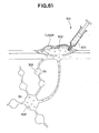
- a magnetic fluid 302 having magnetic properties as a tracer is infused locally in the vicinity of a tumor by use of an injector 301 such as a puncture needle or the like as shown in Fig. 61.
- the magnetic fluid 302 stays in a sentinel lymph node (SN) after a predetermined time period after the infusion.
- the magnetic fluid is magnetized with an electromagnet having a large magnetic force.
- the electromagnet is turned off, the weak residual magnetic field remaining in the magnetic fluid is detected by the SQUID.
- the sentinel lymph node can be detected.
- the magnetic fluid has a very small particle size of several hundreds nm. Thus, the coercive force is small, and the strength of the residual magnetic field is very small. Thus, a magnetic sensor having a high sensitivity such as SQUID or the like is required.
- the magnetic sensor using the high temperature superconducting SQUID (hereinafter, abbreviated to an SQUID magnetic sensor) is operated at a low temperature of about - 190°C.
- the sensor must be cooled with liquefied nitrogen.
- the detection method using the high temperature superconducting SQUID the size of the device is increased, and the manipulation property is deteriorated.
- the detection method using the high temperature superconducting SQUID it is necessary to exchange the liquefied nitrogen every several hours. The running const is high.
- the detection method using the high temperature superconducting SQUID has problems in that the exchange of the liquefied nitrogen is a dangerous work, and so forth.
- the strength of the residual magnetic field remaining in the magnetic fluid is very small.
- the effects of magnetic noise from electrical devices of apparatuses are large, which requires magnetic shielding.
- the size of the detection device must be increased, and the cost becomes high.
- a exciting magnetic field is applied to the magnetic fluid by means of an exciting unit such as an exciting magnet or the like.
- the strength of the magnetic field component extending orthogonally to the exciting magnetic field and in the same magnetic field direction is detected by means of the plural magnetic sensors.
- One of the outputs from the plural magnetic sensors is subtracted from the other output, and the difference is signal-processed. Then, a local distortion in magnetic field distribution (spatial magnetic gradient) occurring due to the magnetic fluid excited with the exciting unit is detected.
- the magnetic fluid detection device described in Japanese Unexamined Patent Application Publication No. 2003-128590 uses magnetic sensors such as Hall elements, magnetic resistance elements, or the like which give an output proportional to the strength of the magnetic field.
- the change of the magnetic field occurring due to the magnetic fluid is very small compared with the exciting magnetic field generated by the exciting unit. Therefore, if the outputs from the magnetic sensors are DC amplified, the outputs from the amplifiers become saturated. Thus, AC amplification must be carried out.
- the magnetic sensors are AC coupled by means of a capacitor or the like, the signal change caused by the magnetic fluid is attenuated, unless the magnetic field is changed at a high speed by the magnetic fluid.
- the outputs from the plural magnetic sensors are subtracted, so that a signal caused by the exciting magnetic field generated by the exciting unit is cancelled out, and the signal change caused by only the magnetic fluid is amplified.
- the magnetic fluid detection device described in Japanese Unexamined Patent Application Publication No. 2003-128590 uses the plural magnetic sensors, a detection portion containing the plural magnetic sensors increases in size. The manipulation property is deteriorated, and he cost increases.
- Figs. 1 to 27 show a magnetic fluid detection device according to a first embodiment of the present invention.
- a magnetic fluid detection device 1 comprises a probe 2, and a control unit 4 for controlling the probe 2 and connected to the probe 2 through a connecting cable 3.
- the probe 2 when applied, is caused to contact the surface of a subject body from the outside of the body, is surgically inserted in an intracavity through a trocar, or is caused to contact the inside of the body after the surface of the body is surgically incised.
- the probe 2 has a grip provided in the proximal-end side thereof so that the probe 2 can be easily gripped.
- the probe 2 has a pistol-like shape for easy handling.
- the probe 2 contains a detection unit 7 disposed in the distal-end side thereof.
- the detection unit 7 detects a magnetic fluid 6 staying in a sentinel lymph node in the subject.
- the detection unit 7 is provided with an exciting unit and a magnetic sensor, which will be described below.
- the control unit 4 comprises a display 8 for displaying detection results obtained by the detection unit 7 and a speaker 9 for acoustically informing an operator of the detection results obtained by the detection unit 7, the display 8 and the speaker 9 being provided on a front panel.
- the display 8 comprises LEDs (Light Emitting Diode), LCD (Liquid Crystal Display), or the like.
- the control unit 4 can inform an operator of detection results of the magnetic fluid 6.
- the probe 2 is covered with a probe sheath 10 made of a non-magnetic material.
- a probe body 11 is exposed.
- the probe 2 with the probe sheath 10 has a water-tight structure for use in an intracavity or the like.
- the probe body 11 comprises a sliding unit 12 provided on the probe distal-end side, and a driving unit 13 provided on the probe proximal-end side.
- the sliding unit 12 is made of a non-magnetic material.
- the sliding unit 12 comprises a vibration rod 14 and a connector 15.
- the vibration rod 14 can be vibrated in the longitudinal axial direction.
- the distal-end side of the connector 15 is connected to the vibration rod 14, and the proximal-end side thereof is connected to the driving unit 13.
- the connector 15 is provided with a crank mechanism and so forth for transmitting vibration from the driving unit 13 to the vibration rod 14.
- the driving unit 13, the vibration rod 14, and the connector 15 constitute a vibration unit.
- the vibration rod 14 is formed to have a longer length than the connector 15 so that the detection unit 7 is separated far from the metallic part of the probe body 11.
- the sliding unit 12 is provided with guides 16 at two positions, that is, on the distal-end side and the proximal-end side thereof. These guides 16 are formed so that the vibration rod 14 can be slid with being guided in the longitudinal axial direction.
- the guide 16a on the distal-end side is fixed on the distal-end side of the vibration rod 14, while the guide 16b on the proximal-end side is fixed on the proximal-end side of the vibration rod 14.
- the driving unit 13 contains a motor 17.
- the driving unit 13 converts the rotational motion of the motor 17 to the advancing and receding motion, which is transmitted to the connector 15.
- the vibration rod 14 is slid on and guided by the guides 16a and 16b, and is vibrated in the longitudinal axial direction accompanying the vibration transmitted from the driving unit 13 via the connector 15.
- the ball bearings and the vibration rod 14, or the ball bearing and the driving unit 13 may adhere to each other, due to the generation of heat, which occurs due to the fact that the vibration distance is short.
- the vibration rod 14 is vibrated while it is slid on and guided by the guides 16, as described above.
- the above-described adhesion, occurring due to the generation of heat, can be eliminated.
- the driving unit 13 may contain a vibrator (not shown) instead of the motor 17 with which the vibration rod 14 is vibrated in the longitudinal axial direction.
- the detection unit 7 is provided in the distal-end side of the vibration rod 14.
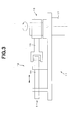
- the detection unit 7 comprises an exciting magnet 21 and a coil 22 provided in the body 23 of the detection unit 7.
- the exciting magnet 21 excites the magnetic fluid 6 staying in the subject.
- the exciting magnet 21 is a permanent magnet such as a neodymium magnet, a samarium - cobalt magnet, or the like.
- the coil 22 functions as a magnetic sensor for detecting a local distortion in magnetic field distribution (special magnetic gradient) which occurs due to the magnetic fluid 6 excited with the exciting magnet 21.
- the vibration rod 14 of the detection unit 7 may be connected directly to the motor 17 of the driving unit 13.
- the coil 22 is provided in the distal-end side of the body 23 of the detection unit.
- the coil 22 is exposed on the distal-end side of the vibration rod 14.
- the exciting magnet 21 is arranged on the rear side of the coil 22.
- the exciting magnet 21 is vibrated in the longitudinal axial direction, accompanying the vibration in the longitudinal axial direction of the vibration rod 14. Thereby, the detection unit 7 generates an AC magnetic field as an exciting magnetic field, in response to the vibration frequency, so that the magnetic fluid 6 staying in the subject can be detected.
- the local distortion of the magnetic field distribution (special magnetic gradient), caused by the magnetic fluid 6, becomes larger in proportion to the strength of the exciting magnetic field (AC magnetic field), so that the magnetic fluid can be easily detected.
- the output of a sensor is saturated, so that a change in magnetic field can not be detected. It is supposed that the distance between the magnetic fluid and the magnetic sensor is at least about 1 mm considering the thickness of a sheath.
- the surface magnetic flux density of the exciting magnet is not less than 0.1 T (tesla).
- Hall devices and magnetic resistance elements cannot be employed.
- the coil 22 is used as a magnetic sensor.
- the exciting magnetic field generated by the exciting magnet 21 is an AC magnetic field.
- the electromotive force v is larger, so that the detection sensitivity can be enhanced.
- the above-described permanent magnets such as neodymium magnets, samarium-cobalt magnets, or the like are small in size and have a large magnetic force. and hence, are suitable for use in the device of this embodiment.
- the surface magnetic flux density is about 0.5 T (tesla).
- the magnetic fluid 6 is excited by the AC magnetic field.
- the local distortion of the magnetic field distribution (spatial magnetic gradient) due to the magnetic fluid 6 is detected in the coil 22.
- the vibration frequency component is detected based on the output of the coil 22, so that magnetic noise occurring due to the terrestrial magnetism, electrical devices or apparatuses, and so forth can be eliminated, as described below.
- the detection unit 7 is provided with a pre-amplification portion 24.
- the pre-amplification portion 24 contains a pre-amplifier 24A for amplifying the output from the coil 22.
- the exciting magnet 21, the coil 22, and the pre-amplification portion 24 are integrally vibrated in the longitudinal axial direction, accompanying the vibration of the vibration rod 14 in the longitudinal axial direction.
- a lead wire provided between the coil 22 and the pre-amplification portion 24 is prevented from being relatively vibrated, so that the detection unit 7 is not influenced with a change in contact resistance or the like.
- a lead wire provided between the pre-amplification portion 24 and a line driver 26 is vibrated.
- the pre-amplification portion 24 amplifies a very small output from the coil 22, the change in magnitude of the output signal, occurring due to the contact resistance change or the like, is very small compared to the amplitude of the amplified output signal.
- the lead wire has no influence on the output signal.
- the spaces between the coil 22, the exciting magnet 21, and the pre-amplification portion 24 are filled with a resin so as to be fixed to each other in the body 23 of the detection unit.
- the line driver 26 for transmitting an output from the detection unit 7 to the control unit 4 is fixed near the vibration rod 14, separately from the vibration rod 14. That is, the line driver 26 is prevented from being vibrated.
- the line driver 26 being relatively heavy is not fixed to the vibration rod 14, and hence, the weight is prevented from adding to that of the vibration rod 14.
- An output from the line driver 26 is transmitted to the control unit 4, in which the signal-processing is carried out.
- the control unit 4 comprises a line receiver 31 for receiving an output from the line driver 26, a low-pass filter 32 (LPF) for eliminating a higher harmonic component from the output received by the line receiver 31 and passing the amplitude component, an amplifier 33 for amplifying a signal from LPF 32, an A/D converter 34 for A/D converting a signal from the amplifier 33, and a digital signal processing circuit 35 comprising, e.g., DSP (Digital Signal Processor) or the like for processing a digital signal A/D converted by the A/D converter 34 and driving the display or the speaker.
- DSP Digital Signal Processor
- control unit 4 contains a motor control circuit 36 for controlling and driving the motor 17 of the driving unit 13.
- the motor control circuit 36 outputs a motor drive signal to drive the motor 17, and also, receives a servo signal from the motor 17 to carry out the feedback control, so that the rotational speed of the motor can be stabilized.
- the motor control circuit 36 outputs a pulse signal synchronous with a rotational signal of the motor 17 to the digital signal processing circuit 35.
- the digital signal processing circuit 35 demodulates the output signal from the coil 22 (the digital signal from the A/D converter 34), based on the pulse signal synchronous with the rotation of the motor from the motor control circuit 36, and detects the magnitude of the vibration frequency component, and drives the display 8 or the speaker 9 based on the detected signal magnitude.
- the pulse signal synchronous with the rotation of the motor is digitally multiplied by the output signal from the coil 22 (the digital signal from the A/D converter 34), or the output signal from the coil 22 is subjected to the high speed Fast Fourier Transform (FFT), and then, the frequency component having the vibration frequency determined based on the pulse signal synchronous with the rotation of the motor is determined.
- FFT Fast Fourier Transform
- the output signal from the coil 22 (the digital signal from the A/D converter 34) can be demodulated while the vibration frequency is set at a constant value, and thus, the pulse signal synchronous with the rotation of the motor is not necessary.
- the digital signal processing circuit 35 can change the luminance, flashing speed of LED of the display 8, the display state of an indicator composed of LEDs or the like, numerical display or indicator display on LCD, and so forth, in response to the magnitude of a detected signal.
- the digital signal processing circuit 35 can change the sound volume, the frequency, and the pulse train frequency of the speaker 9 in response to the magnitude of a detected signal.
- the control unit 4 shown in Fig. 6 is configured so as to process a digital signal.
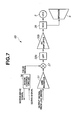
- the control unit 4 may be configured so as to process an analog signal as shown in Fig. 7.
- a control unit 4B comprises the line receiver 31, a multiplier 37 for multiplying an output from the line receiver 31 by a pulse signal from the motor control circuit 36, LPF 32b for eliminating a higher harmonic component from the output from the multiplier 37 and passing a amplitude component, a DC amplifier 33b for amplifying an analog signal from LPF 32b, and a voltage controlled oscillator (VOC) 38 for driving the display 8 and the speaker 9 similarly to the digital signal processing circuit 35, in response to the strength of an analog signal (voltage) from the DC amplifier 33b.
- VOC voltage controlled oscillator
- a control unit may be configured so that detection results of the magnetic fluid 6 are displayed on a monitor on which an endoscope image is displayed, as shown in Fig. 8.
- a control unit 4C contains a synthesizing circuit 41 for synthesizing an endoscope image signal output from the endoscope device 40 with the detection results.
- the control unit 4C outputs the synthesized image signal from the synthesizing circuit 41 onto a monitor 42.
- the endoscope image and the detection results of the magnetic fluid 6 are displayed on the screen of the monitor.
- the coil 22 is used as a magnetic sensor according to the present embodiment.
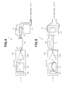
- the coil 22 having a large aperture as shown in Figs. 9 and 10 has a large area in which magnetic noise 6b from electrical devices or apparatuses and so forth is detected in addition to the magnetic force lines 6a generated by the magnetic fluid 6.
- the magnetic force lines 6a are covered with the magnetic noise 6b, and thus, the detection sensitivity is reduced.
- the sizes of lymph nodes of a person are about 1 cm.
- the aperture 22a of the coil 22 is set at a size smaller than 1 cm, and thus, the aperture 22a has a size smaller than a lymph node as shown in Figs. 11 and 12.
- the coil 22 reduces as much as possible the area of detecting magnetic noise 6b from electrical devices or apparatuses, as shown in Fig. 13.
- the coil 22 can detect only the magnetic force lines 6a generated by the magnetic fluid 6.
- the detection unit 7 is vibrated at an amplitude of about 1 mm to 2 mm in the longitudinal axial direction, which is caused by the vibration of the vibration rod 14 in the longitudinal axial direction.
- the detection unit 7 it is necessary to provide a space having a size of about 1 to 2 mm between the detection unit 7 and the probe sheath 10 so that the detection unit 7 can be vibrated (see Fig. 15).
- the thickness of the probe sheath 10 is in the range of about 0.5 to 1 mm.
- the distance between the magnetic fluid and the coil 22 at which the magnetic fluid can be detected by the coil 22 is not more than about 5 mm.
- a top cover 50 and the probe sheath 10, constituting a sheath are formed separately from each other in such a manner that the distance between the top cover 50 and the body 23 of the detection unit can be adjusted.
- the top cover 50 is fixed onto the probe sheath 10 via an adjusting piece 43.
- the adjusting piece 43 can be fixed to the probe sheath 10 through a screw portion 51 with a fine pitch.
- the adjusting piece 43 is fixed onto the probe sheath 10 at a position thereof where the end-face of the adjusting piece 43 slightly protrudes from the surface of the body 23 of the detection unit.
- the top cover 50 is placed onto the adjusting piece 43 and fixed thereto.
- the distance between the top cover 50 and the detection unit body 23 is minimized, and the detection range for the magnetic fluid 6 is maximized.
- the top cover 50 is slid on and attached to the probe sheath 10 as shown in Fig. 15.
- the top cover 50 is pulled out from the position at which the top cover 50 contacts with the detection unit body 23, and then is fixed.
- the method shown in Fig. 15 is simple compared to the method shown in Fig. 14, although the accuracy is slightly low.
- the top cover 50 is fixed onto the detection unit body 23 via the screw portion 51 with a fine pitch.
- the top cover 50 is provided with an O-ring 44 considering the water-tightness between them.
- the top cover 50 is slightly pulled out from the position at which the top cover 50 contacts with the detection unit body 23, and then is fixed using an adhesive 45.
- the magnetic fluid detection device 1 formed as described above, detects the magnetic fluid 6 staying in a sentinel lymph node 5 of a subject to identify the sentinel lymph node 5.
- an operator punctures the lower layer of a lesion of the subject with a puncture needle (not shown), and infuses the magnetic fluid 6 locally in the vicinity of the lesion. Then, the magnetic fluid 6 infused in the vicinity of the lesion is moved from the infusion position to a lymph vessel, reaches the sentinel lymph node 5 five or fifteen minutes after the infusion, and stays in the sentinel lymph node 5.
- the operator surgically inserts the probe 2 of the magnetic fluid detection device 1 into an intracavity, e.g., via a trocar (not shown), or is placed on the surface of the subject body from the outside of the body.
- the operator detects the magnetic fluid 6 staying in the sentinel lymph node 5 while the operator moves the distal end of the probe 2 in the vicinity of the lesion of the patient.
- the motor 17 of the driving unit 13 is driven while it is controlled with the motor control circuit 36 of the control unit 4.
- the rotational motion of the motor 17 is converted to the advancing and receding motion, and the vibration is transmitted to the connector 15.
- the vibration rod 14 is vibrated in the longitudinal axial direction by the vibration transmitted from the driving unit 13 via the connector 15, while the vibration rod 14 is slid and guided by the guides 16a and 16b.
- the detection unit 7 is vibrated in the longitudinal axial direction.
- the exciting magnet 21 of the detection unit 7 is vibrated in the longitudinal axial direction.
- the probe 2 generates an AC magnetic field depending on the vibration frequency.
- the AC magnetic field generated by the exciting magnet 21 excites the magnetic fluid 6 via the space in the vicinity of the probe. Then, the AC magnetic field is attracted or repelled in the vicinity of the magnetic fluid 6, so that the magnetic field distribution is locally distorted, and thus, the spatial gradient (magnetic flux density) of the magnetic field distribution changes. This local distortion of the magnetic field distribution (change of magnetic flux density), occurring due to the magnetic fluid 6, is detected by the coil 22.
- the coil 22 can detect the local distortion of the magnetic field distribution occurring due to the magnetic fluid 6 without being influenced with the exciting magnetic field (the AC magnetic field from the standpoint of the magnetic fluid 6, and the static magnetic field from the standpoint of the coil 22), as described above.
- An output from the coil 22 is amplified by the pre-amplifier 24A, and is transmitted to the control unit 4 via the line driver 26.
- the pre-amplification portion 24, together with the exciting magnet 21 and the coil 22, is vibrated in the longitudinal axial direction, accompanying the vibration of the vibration rod 14 in the longitudinal axial direction.
- the lead wire between the coil 22 and the pre-amplification portion 24 is not vibrated, so that no change in the contact resistance or the like occurs, and hence, the detection unit 7 is not affected by such change.
- the lead wire between the pre-amplification portion 24 and the line driver 26 is vibrated.
- the fine output from the coil 22 is amplified in the pre-amplification portion 24.
- the change of the signal is slight compared to the signal magnitude after the amplification is carried out.
- such change of the contact resistance or the like does not exert an influence on the output signal substantially.
- the line receiver 31 receives the output signal.
- LPF32 eliminates the higher harmonic component from the output from the line receiver 31, so that the amplitude component passes through LPF 32.
- the amplitude component is amplified by the amplifier 33 and is A/D converted by the A/D converter 34.
- the digital signal processing circuit 35 demodulates the output signal from the coil 22 (the digital signal from the A/D converter 34), based on the pulse signal synchronous with the rotation of the motor output from the motor control circuit 36, detects the amplitude of the vibration frequency component, and drives the display 8 and the speaker 9 in response to the detected signal magnitude.
- the pulse signal synchronous with the rotation of the motor is digitally multiplied by the output signal from the coil 22 (the digital signal from the A/D converter 34), or the output signal from the coil 22 is subjected to the high speed Fourier transform, and then, the frequency component having the vibration frequency determined based on the pulse signal synchronous with the rotation of the motor is determined.
- the output from the coil 22 (the digital signal from the A/D converter 34) can be demodulated while the vibration frequency is set at a constant value, and thus, the pulse signal synchronous with the rotation of the motor is not necessary.
- the display 8 displays the local distortion of the magnetic field distribution using an indicator or figures.
- the display 8 displays the indicator or figures in such a manner that when the probe distal end approaches the magnetic fluid 6, the swing of the indicator becomes larger, or the numerical value becomes larger, and when the probe distal end becomes more distant from the magnetic fluid 6, the swing of the indicator becomes smaller or the numerical value becomes smaller.
- the speaker 9 generates such a sound as corresponds to the local distortion of the magnetic field distribution (spatial magnetic gradient). In this case, when the probe distal end approaches the magnetic fluid 6, the sound emitted from the speaker 9 is larger. When the probe distal end becomes more distant from the magnetic fluid 6, the sound is smaller.
- the speaker 9 may generate a sound of which the frequency is proportional to the distance between the probe 2 and the magnetic fluid 6.
- the magnetic fluid detection device 1 of the first embodiment has a small size, is superior in manipulation property, and can accurately detect the position of the magnetic fluid 6 staying in the sentinel lymph node 5 to identify the position of the sentinel lymph node 5.
- Feridekkusu generally name; ferumoxides
- MnZn ferrite MnZn ferrite
- Fe 3 O 4 magnetite or the like may be used for the magnetic fluid 6.
- the concentration of the magnetic fluid 6 becomes low when it stays in a lymph node.
- the force for distorting the magnetism is small. It is estimated that the relative magnetic permeability is substantially about 1.0001.
- the output signal of the coil 22 is amplified so as to obtain a large gain.
- the output signal of the coil 22 is affected by a magnet used in the motor 17 for vibration disposed in the detection unit body 23 that is positioned farther from the coil 22 compared to the exciting magnet 21.
- the device is assembled in such a manner that the magnetic poles of the exciting magnet 21 and those of a motor magnet 60 are arranged in the same direction, as shown in Fig. 18.
- the magnetic field is distorted as shown in Fig. 13.
- the magnetic field applied to the coil 22 increases.
- the coil 22 becomes more distant from the motor magnet 60, and thus, the magnetic field from the motor magnet 60 applied to the coil 22 decreases. That is, the effect of the motor magnet 60 on the coil 22 (the magnetic field generated by the motor magnet 60 applied to the coil 22) decreases, while the effect of the magnetic fluid 6 on the coil 22 (the magnetic field generated by the magnetic fluid 6 applied to the coil 22) increases.
- the magnetic field from the motor magnet 60 becomes small.
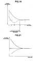
- the polarities of the exciting magnet 21 and those of the motor magnet 60 are opposite to each other, the magnetic fields generated by the exciting magnet 21 and the motor magnet 60 are intensified by each other. Accordingly, the magnitude of the signal output from the coil 22 is shown by solid line in Fig. 19.
- the magnitude of the signal output from the coil 22 does not become lower than that obtained when no magnetic fluid exists. Therefore, the signal from the coil 22 can be measured in the range to the position d in Fig. 19.
- the detection distance of the magnetic fluid can be maximized by assembling the device in such a manner that the magnetic poles of the exciting magnet 21 and those of the motor magnet 60 are arranged in directions opposite to each other.
- a correcting magnet 61 may be arranged in such a direction as to cancel out the magnetic field generated by the motor magnet 60.
- the relative magnetic permeability of water is about 0.999991.
- the difference in relative magnetic permeability between air and water is 0.00001.
- the difference is in the range of one fifth to one tenth of the difference in relative magnetic permeability between the magnetic fluid and water.
- the relative magnetic permeability of the magnetic flux is nearly equal to that of air, and no significant difference between them is found.
- the coil 22 exhibits a large output signal magnitude, as shown in Fig. 21, due to the effect of the magnetic field of the correcting magnet 61, even when the probe 2 is set in the air.
- the magnetic poles of the correcting magnet 61 and those of the exciting magnet 21 are arranged in directions opposite to each other.
- the magnetic field applied from the magnetic fluid to the coil 22 increases, while the magnetic field applied from the correcting magnet 61 to the coil 22 decreases. Since the magnetic poles of the correcting magnet 61 and those of the exciting magnet 21 are arranged in the opposite directions, the magnetic fields are intensified by each other.
- the magnitude of the signal output from the coil 22 is shown by a solid line in Fig. 21.
- the strength of the magnetic field applied to the coil 22 decreases, since the relative magnetic permeability of water is less than 1. Also, the strength of the magnetic field applied from the correcting magnet to the coil 22 also decreases.
- the magnetic fields from the correcting magnet 61 and the exciting magnet 21 are directed so as to be cancelled out by each other, since the magnetic poles of them are arranged in the opposite directions. Accordingly, the magnitude of the signal output from the coil 22 is shown by a dotted line in Fig. 21.
- the change of the signal caused by water and the magnetic fluid may be reversed by increasing the magnetic force of the correcting magnet 61, thereby enabling detection of the magnetic fluid in the living body.
- the detection unit is configured as shown in Fig. 22.
- a correcting coil 62 for detecting a positional shift of the coil 22 is wound around the exciting magnet 21, and Ac current is supplied from the an AC electric source to the correcting coil 62.
- the strength of an AC magnetic field f1 generated by the correcting coil 62 is set at such a low value that the AC magnetic field f1 can affect the coil 22 only, not exerting an influence onto the magnetic fluid 6.
- the noise by the positional shift of the coil 22, in addition to the local distortion of the magnetic field distribution (spatial magnetic gradient) occurring due to the magnetic fluid 6, is superposed on the magnitude of the signal detected by the coil 22 in the vicinity of a vibration frequency f0 shown in Fig. 23.
- the noise occurring due to the positional shift of the coil 22 is also superposed on the AC magnetic field f1 of the correcting magnet 61.
- the effect of the magnetic fluid 6 is not superposed on the AC magnetic field f1.
- the strength of the AC magnetic field f1 multiplied by a predetermined coefficient is subtracted from the magnitude of the signal in the vicinity of the vibration frequency f0. Thereby, the noise occurring due to the positional shift of the coil 22 can be eliminated.
- the noise generated by the positional shift of the coil 22 can be eliminated by the subtraction-processing of the output from the coil 22 in the control unit 4.
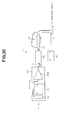
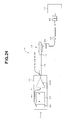
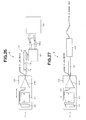
- the magnetic fluid detection device 1 may be configured as shown in Figs. 24 to 27, so that affects by the motor magnet 60 can be eliminated.
- the motor 17 is disposed far from the probe side using a flexible shaft 64.
- Couplers 65 are used for the connection of the connector 15 to the flexible shaft 64 and for the connection of the flexible shaft 64 to the motor 17.
- the rotational motion of the motor 17 is transmitted via the flexible shaft 64 and the couplers 65, and the transmitted rotational motion of the motor 17 is converted to the advancing and receding motion. Then, the vibration is transmitted to the connector 15.
- the detection unit 7 is positioned far from the probe side, and hence, the detection unit 7 is prevented from being affected by the motor magnet 60.
- the connector 15 has a hydraulic driving mechanism 66.
- the motor 17 is positioned far from the probe side using the hydraulic driving mechanism 66.
- cylinders 60a are arranged on the probe side and on the motor side.
- the rotational movement of the motor 17 is converted to the advancing and receding motion, in which oil 66b is advanced and receded.
- the vibration is transmitted.
- the vibration is transmitted to the vibration rod 14 by means of the hydraulic driving mechanism 66 of the connector 15.
- the probe side is positioned far from the motor 17, so that the detection unit 7 is prevented from being affected by the motor magnet 60.
- an air motor 67 is provided on the probe side.
- An air compressor 68 for driving the air motor 67 is positioned far from the probe side.
- the magnetic fluid detection device 1D air is supplied to and discharged from the air compressor 68 via air tubes 68a so that the air motor 67 is rotated.
- the rotational motion is converted to the advancing and receding motion.
- the vibration is transmitted to the connector 15.
- the air motor 67 with no magnets is provided on the probe side, and hence, the detection unit 7 is prevented from being affected by the motor magnet 60.
- a magnetic fluid detection device 1E shown in Fig. 27 contains a supersonic motor or electrostatic actuator 69 provided with no magnets.
- the magnetic fluid detection device 1E drives and controls the supersonic motor or electrostatic actuator 69 to transmit vibration to the vibration rod 14.
- the magnetic fluid detection device 1E contains the supersonic motor or electrostatic actuator 69 provided with no magnets. Thus, the detection unit 7 is prevented from being affected by the motor magnet 60.
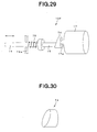
- Figs. 28 to 38 show a magnetic fluid detection device according to a second embodiment of the present invention.
- the probe 2 and the control unit 4 are formed as separate pieces.
- a control unit is contained in a probe.
- the other configuration is the same as that of the first embodiment. Thus, the description is not repeated.
- the same components as those of the first embodiment are designated by the same reference numerals.
- a probe 2F contains the control unit 4 as shown in Fig. 28.
- the probe 2F is provided with a control substrate 71 having a control circuit mounted thereon as a control unit.
- the control substrate 71 is provided on the back side of the driving unit 13F.
- a battery 72 for supplying an electric power is provided on the back side of the control substrate 71.
- the control substrate 71 is provided with LED 73 as a display.
- the LED 72 is connected to the control substrate 71.
- the battery 72 may be charged with electromotive power from a charging coil 72A.
- the sheath 10F of the probe 2F is formed so as to be transparent. Thus, the light-emitting state of the LED 73 can be seen through the probe sheath 10F.
- the driving unit 13F contains the motor 17.
- the driving unit 13F contains the motor 17 and an eccentric cam 74 disposed on an output shaft 17a of the motor 17.
- the connector 15 is installed consecutively with the eccentric cam 74.
- the vibration rod 14 is biased with a spring 75 so as to be connected to the distal-end side of the connector 15.
- the spring 75 when it is pressed against the distal-end side of the connector 15, is given a biasing force by means of a spring-stopper 75a.
- the motor 17 of the driving unit 13 is rotated against the biasing force of the spring 75 under control by the control circuit on the control substrate 71. Then, in the probe 2F, the rotational motion of the motor 17 is converted to the advancing and receding motion by means of the eccentric cam 74, and is transmitted to the connector 15. In the probe 2F, the vibration rod 14 is driven in the longitudinal axial direction through the connector 15.
- the magnetic fluid detection device 1F has the advantages as those of the first embodiment. Moreover, the size can be reduced, and its manipulation property is superior.
- the coil 22 detects a change in magnetic flux (a change in magnetic flux density) passing through the aperture 22a. According to the Faraday's electromagnetic induction law, the output (electromotive voltage) signal from the coil 22 increases with the crossing speed rate over the magnetic flux being increased.
- the probe is configured so that the detection rate increases.
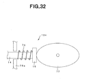
- a driving unit 13G contains a cam 76 having a step portion instead of the eccentric cam 74.
- a driving unit 13H contains a elliptic cam 77 instead of the cam 76 having a step portion.
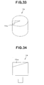
- the cam 76 has a step portion formed on the outer peripheral surface thereof. However, the step portion may be formed on an end-face of the cam 76, as shown in Figs. 33 and 34.
- the connector 15 is rapidly (instantaneously) receded by using the cam 76 having a step portion of the driving unit 13G or by using the elliptic cam 77 of the driving unit 13H, so that the vibration rod 14 is rapidly receded.
- the coil 22 can output a very large output (electromotive voltage) signal.
- the vibration rod 14 is advanced and receded as shown in Fig. 35.
- the output signal of the coil 22 is generated as shown in Fig. 36, accompanying the advancing and receding motion.
- the control circuit provided on the control substrate 71 carries out the following signal-processing of a signal output from the coil 22.
- control circuit calculates the average values A ve S1, A ve S2, A ve S3, ⁇ of the magnitudes of the signal obtained when the vibration rod 14 is rapidly receded, and also, calculates the average values A ve N1, A ve N2, A ve N3, ... of the magnitudes of the signal obtained immediately after the receding.
- the magnetic fluid 6 is detected in the time intervals in which the average values A ve S1, A ve S2, A ve S3, ⁇ of the magnitudes of the signal obtained when the vibration rod 14 is rapidly (instantaneously) receded are shown. Moreover, the speed of the vibration rod 14 is higher in these time intervals.
- the vibration rod 14 is positioned farthest from the magnetic fluid 6 in the time intervals in which the average values A ve N1, A ve N2, A ve N3, ⁇ is immediately after the receding.
- the magnitudes of the signal are not affected by the magnetic fluid 6, and also, the speed of the vibration rod 14 is low in these time intervals. That is, these signals represent noise components.
- noise components can be eliminated by subtracting the average values A ve N1, A ve N2, A ve N3, ⁇ , obtained immediately after the vibration rod 14 is receded, from the average values A ve S1, A ve S2, A ve S3 , ⁇ , obtained when the vibration rod 14 is rapidly (instantaneously) receded.
- the measuring time interval in which the magnitude of the signal is averaged is set so as to be equal to integer times the one period of a commercial electric source.
- the noise of the commercial electric source is averaged based on the one period or integer times the one period.
- the value of the noise becomes substantially zero. Therefore, the effect of the noise of the commercial electric source can be substantially eliminated.
- Fig. 37 shows the resultant signal.
- SO1 is a value obtained by subtracting A ve N1 from A ve S1
- SO2 is a value obtained by subtracting A ve N2 from A ve S2
- SO3 is a value obtained by subtracting A ve N3 from A ve S3.
- the control circuits keeps SO1 until the next SO2 is obtained. After SO2 is obtained, the control circuit keeps SO2 until the next SO3 is obtained. Thereby, a signal showing whether the magnetic fluid 6 is present or absent is obtained.
- the magnetic fluid detection device F can detect the magnetic fluid 6 more accurately.
- a higher harmonic component 2f0 with respect to the fundamental frequency f0 which is the vibration frequency
- a higher harmonic component 2f0 with respect to the fundamental frequency f0 which is the vibration frequency
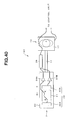
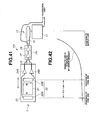
- Figs. 39 to 46 show a magnetic fluid detection device according to a third embodiment of the present invention.
- one coil 22 is used as a magnetic sensor.
- plural magnetic sensors are used.
- Other configuration is the same as that of the first embodiment, and the description is not repeated.
- the same components as those of the first embodiment are designated by the same reference numerals.
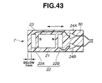
- a magnetic fluid detection device 101 contains plural coils 22 (two coils 22A and 22B) as magnetic sensors.
- the coil 22A is disposed on the distal-end side of the detection unit body 23, and is exposed on the distal-end portion of the vibration rod 14.
- the exciting magnet 21 is arranged on the back side of the coil 22A.
- the coil 22B is arranged on the back side of the exciting magnet 21. That is, the exciting magnet 21 is arranged between the coil 22A and coil 22B.
- the vibration rod 14 may be connected directly to the motor 17 of the driving unit 13.
- the output of one of the plural coils 22A and 22B is subtracted from that of the other coil in order to eliminate magnetic noise, e.g., caused by the terrestrial magnetism, the effect of the magnetic field generated by the motor magnet of the motor 17, or the like.
- the difference between the outputs of the plural coils 22 is calculated, the magnetic noise caused by the terrestrial magnetism or the like is removed, and then, the vibration frequency component is detected, as described below.
- the magnetic noise caused by the terrestrial magnetism, electrical devices or apparatuses, and so forth is removed.
- the apertures of the plural coils 22 are set at not more than 1 cm, i.e., are set so as to be smaller than a lymph node, as described in the first embodiment. Thereby, the range where the coils 22 (22A and 22B) detect magnetic noise occurring due to electrical devices or apparatuses can be minimized, and thus, the coils 22 can detect only the magnetic force lines generated by the magnetic fluid 6.
- pre-amplification portion 24 plural pre-amplification portions, that is, pre-amplification portions 24A and 24B for amplifying the outputs from the plural coils 22 (coils 22A and 22B) are provided.
- the pre-amplification portion 24A amplifies the output from the coil 22A
- the pre-amplification portion 24B amplifies the output from the coil 22B.
- the line driver 26 is provided with a subtracter 27 for calculating the difference between the outputs of the plural coils 22 (22A and 22B), and an amplifier 28 for amplifying the output from the subtracter 27.
- the output from the line driver 26 is transmitted to the control unit 4, and is signal-processed therein.
- control unit 4 The configuration of the control unit 4 is the same as that descried in the first embodiment, and the description is not repeated.
- the plural coils 22, e.g., the coils 22A and 22B are used.
- the magnetic field generated by a motor magnet (not shown) of the motor 17 is applied to the coils 22.
- the strengths of the magnetic field applied to the coils 22 change with the distances between the coils 22 and the motor magnet.
- the strengths of the magnetic field applied to the coils 22 change.
- voltages are output from the coils 22. The voltages have no relation to the magnetic fluid, and hence, become noise when the magnetic fluid is detected.
- the magnetic field from the motor magnet is exponentially attenuated proportionally to the distance from the motor magnet in the vicinity of the motor magnet.
- the gradient of the electromagnetic field attenuation may be estimated to be constant in the range of a few centimeters in the vicinity of the plural coils 22 which are significantly distant from the motor magnet.
- the magnitudes of the electromagnetic field applied from the motor magnet to the coils 22A and 22B change to the same degrees, and thus, the voltages output from the coils 22A and 22B are equal.
- the effects of the motor magnets on the coils 22A and 22B can be eliminated by subtracting the output of one of the coils 22A and 22B from that of the other coil.
- a resin 80 is filled into the spaces existing in the body 23 of the detection unit 7 and hardened so that the plural coils 22 (22A and 22B), the exciting magnet 21, and the pre-amplification portion 24 contained in the detection unit body 23 are fixed. That is, the coils 22A and 22B are arranged in parallel and fixed by means of the resin 80. Therefore, when the detection unit 7 is vibrated accompanying the vibration of the vibration rod 14, the directions and the positions of the coils 22A and 22B are prevented from relatively changing.
- the detection unit 7 is vibrated, e.g., over a length of 1 to 2 mm in the longitudinal axial direction accompanying the vibration of the vibration rod 14 in the longitudinal axial direction. Therefore, for the vibration of the detection unit 7, a space having a size of 1 to 2 mm is provided between the detection unit 7 and the probe sheath 10.
- the magnitude of a magnetic field decreases inversely proportional to the square of the distance from a vibration source. Therefore, desirably, the coil 22A is located as near to the distal-end side of the detection unit 7 as possible.
- the coil 22A is located at a position of not more than 1 mm from the distal end of the detection unit body 23.
- the coils 22A and 22B are relatively moved, due to the vibration of the detection unit 7. Thus, their relative directions and positions are changed. Then, the magnetic force lines of the terrestrial magnetism extending across the coils 22A and 22B change. Accordingly, even if the subtraction is carried out on the outputs of the coils 22A and 22B, the magnetic noise, generated by the resultant magnetic field formed of the magnetic field by the motor magnet and the terrestrial magnetism as described above, cannot be eliminated.
- the directions and the positions of the coils 22A and 22B are prevented from relatively changing, although the detection unit 7 is vibrated accompanying the vibration of the vibration rod 14. Therefore, the magnetic force lines of the terrestrial magnetism extending across the coils 22A and 22B change in the same manners with respect to the coils 22A and 22B.
- the magnetic noise which is generated by the resultant magnetic field formed from the magnetic field by the motor magnet and that by the terrestrial magnetism, as described above, can be eliminated by the subtraction of the outputs of the coils 22A and 22B.
- the magnetic fluid detection device 101 is applied to detect the magnetic fluid 6 staying in the sentinel lymph node 5 of a subject to identify the sentinel lymph node 5.
- an operator punctures the lower layer of a lesion of the subject with a puncture needle (not shown), and infuses the magnetic fluid 6 locally in the vicinity of the lesion. Then, the magnetic fluid 6 infused in the vicinity of the lesion is moved from the infusion position to a lymph vessel, reaches the sentinel lymph node from five to fifteen minutes after the infusion, and stays in the sentinel lymph node 5.
- the operator surgically inserts the probe 2 of the magnetic fluid detection device 101 into an intracavity, e.g., via a trocar (not shown), or is placed on the surface of the subject body from the outside of the body.
- the operator detects the magnetic fluid 6 staying in the sentinel lymph node 5 while the operator moves the distal end of the probe 2 in the vicinity of the lesion of the patient.
- the motor 17 of the driving unit 13 is driven while it is controlled by the motor control circuit 36 of the control unit 4.
- the rotational motion of the motor 17 is converted to the advancing and receding motion, and the vibration is transmitted to the connector 15.
- the vibration rod 14 is vibrated in the longitudinal axial direction by the vibration transmitted from the driving unit 13 via the connector 15, while the vibration rod 14 is slid and guided by the guides 16a and 16b.
- the detection unit 7 is vibrated in the longitudinal axial direction.
- the exciting magnet 21 of the detection unit 7 is vibrated in the longitudinal axial direction.
- the probe 2 generates an AC magnetic field depending on the vibration frequency.
- the AC magnetic field generated by the exciting magnet 21 excites the magnetic fluid 6 via the space in the vicinity of the probe. Then, the AC magnetic field is attracted or repelled in the vicinity of the magnetic fluid 6, so that the magnetic field distribution is locally distorted, and thus, the spatial gradient (magnetic flux density) of the magnetic field distribution changes.
- This local distortion of the magnetic field distribution (the change of the magnetic flux density), occurring due to the magnetic fluid 6, is detected by the plural coils 22 (22A and 22B).
- the coils 22A and 22B can detect the local distortion of the magnetic field distribution (the spatial magnetic gradient) occurring due to the magnetic fluid 6 without being influenced with the exciting magnetic field (the AC magnetic field). Outputs from the coils 22A and 22B are amplified by the pre-amplifiers 24A and 24B, and are transmitted to the line driver 26.
- the subtracter 27 carries out the subtraction of the outputs from the coils 22A and 22B, and the difference is amplified by the amplifier 28 and transmitted to the control unit 4.
- the pre-amplification portion 24 together with the exciting magnet 21 and the plural coils 22 (22A and 22B), is vibrated in the longitudinal axial direction, accompanying the vibration of the vibration rod 14 in the longitudinal axial direction.
- lead wires between the coils 22 (22A and 22B) and the pre-amplification portion 24 are not vibrated, so that no change in the contact resistance or the like occurs, and hence, the control unit 4 is not affected by such change.
- the lead wires between the pre-amplification portion 24 and the line driver 26 is vibrated.
- the fine outputs from the coils 22 are amplified in the pre-amplification portion 24.
- the change of the signal is slight compared to the signal magnitude after the amplification is carried out.
- such change of the contact resistance or the like does not exert an influence on the output signal substantially.
- the higher harmonic component of the output signal received by the line receiver 31 is eliminated therefrom by LPF 32, and the amplitude component is taken out.
- the amplitude component taken out is amplified by the amplifier 33, and is A/D converted by the A/D converter 34.
- the digital signal processing circuit 35 carries out digital-signal-processing such as high speed Fourier transformation or the like of the outputs from the plural coils 22 (22A and 22B) (the digital signal from the A/D converter 34), based on the pulse signal from the motor control circuit 36, thereby to detect the amplitude of the vibration frequency component.
- the display 8 and the speaker 9 are driven in response to the detected signal magnitude.
- the display 8 and the speaker 9 operate in the same manners as described in the first embodiment to inform the operator.
- the magnetic fluid detection device 101 of the third embodiment can accurately detect the position of the magnetic fluid 6 staying in the sentinel lymph node 5 to identify the position of the sentinel lymph node 5 without being affected by the magnetic noise of the terrestrial magnetism or the like.
- Figs. 47 to 54 show a magnetic fluid detection device according to a forth embodiment of the present invention.
- the probe 2 and the control unit 4 are formed as separate pieces.
- a control unit is contained in a probe.
- the other configuration is the same as that of the third embodiment. Thus, the description is not repeated.
- the same components as those of the third embodiment are designated by the same reference numerals.
- a probe 2H contains the control unit 4 as shown in Fig. 47.
- the probe 2H is provided with the control substrate 71 having a control circuit mounted thereon as a control unit.
- the control substrate 71 is provided on the back side of the driving unit 13H.
- the battery 72 for supplying an electric power is provided on the back side of the control substrate 71.
- the control substrate 71 is provided with LED 73 as a display.
- the LED 72 is connected to the control substrate 71.
- the battery 72 may be charged with electromotive power from the charging coil 72A.
- the sheath 10H of the probe 2H is formed so as to be transparent. Thus, the light-emitting state of the LED 73 can be seen through the probe sheath 10H.
- the driving unit 13H contains the motor 17.
- the driving unit 13H contains the motor 17 and the eccentric cam 74 disposed on the output shaft 17a of the motor 17.
- the connector 15 is installed consecutively with the eccentric cam 74.
- the vibration rod 14 is biased with a spring 75 so as to be connected to the distal-end side of the connector 15.
- the spring 75 when it is pressed against the distal-end side of the connector 15, is given a biasing force by means of the spring-stopper 75a.
- the motor 17 of the driving unit 13 is rotated against the biasing force of the spring 75 under control by the control circuit on the control substrate 71. Then, in the probe 2H, the rotational motion of the motor 17 is converted to the advancing and receding motion by means of the eccentric cam 74, and is transmitted to the connector 15. In the probe 2H, the vibration rod 14 is vibrated in the longitudinal axial direction through the connector 15.
- the magnetic fluid detection device 1H of the fourth embodiment has the advantages as those of the first embodiment. Moreover, the size can be reduced, and its manipulation property is superior, since the probe contains the control unit.
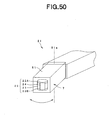
- the probe may be configured in such a manner that the distal-end portion of the probe can swing (be shaken) in the right and left direction, and thereby the probe is vibrated in the right and left direction, as shown in Fig. 50.
- the probe 2I is configured in such a manner that the distal-end portion 81 thereof can swing in the right and left direction about a fulcrum 81a as a center. Therefore, the movement amount of the detection unit 7 in the right and left direction increases. Thus, the movement speed of the probe 2I can be increased.
- the coils 22 (22A and 22B) detect a change in the magnetic flux extending across the aperture (a change in the magnetic flux density).
- the outputs (electromotive voltage) signal from the coils 22 increases according to the Faraday's electromagnetic induction law.
- the movement speed of the detection unit 7 is increased, and thus, the movement speeds of the coils 22A and 22B are increased, so that the coils 22A and 22B output large output (electromotive voltage) signals.
- a permanent magnet is used as the exciting unit comprising the exciting magnet 21.
- the exciting magnetic field generated by the exciting magnet 21 is an AC magnetic field.
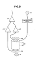
- the exciting unit may comprise an exciting electromagnet 90 shown in Fig. 51.
- the exciting electromagnet 90 is formed by winding a coil 92 around an iron core 91.
- AC current is supplied from an AC source 94 to the coil 92 of the exciting electromagnet 90 via an electromagnet driver 93.
- the electromagnet driver 93 is driven under control by the control unit 4.
- the magnetic fluid 6 staying in the subject is excited with the AC magnetic field generated by the exciting electromagnet 90.
- the local distortion of the magnetic field distribution (spatial magnetic gradient), generated by the magnetic fluid 6, is detected by the coils 22 (22A and 22B).
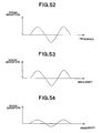
- the outputs of the coils 22 are shown in Figs. 52 and 53.
- the subtraction between the outputs of the coils 22 (22A and 22B) is carried out by the subtracter 27.
- the difference signal is shown, e.g., in Fig. 54.
- the output signals from the coils 22A and 22B have an equal magnitude.
- the difference in magnitude between the magnitudes of the output signals becomes zero, e.g., in Fig. 54.
- the output signal from the coil 22A, positioned relatively near to the magnetic fluid 6, is higher than that from the coil 22B.
- the signal magnitude obtained by subtracting one from the other is exhibited depending on the frequency of the AC magnetic field, as shown in Fig. 54.
- the magnetic fluid detection device using the exciting electromagnet 90 instead of the exciting magnet 21 can detect the magnetic fluid 6.
- the structure of the magnetic fluid detection device is simple. The size can be reduced, and the manipulation property is superior.
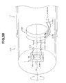
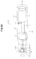
- Figs. 55 to 58 show a magnetic fluid detection device according to a fifth embodiment of the present invention.
- the detection unit 7 is vibrated in the longitudinal axial direction. According to the fourth embodiment, the detection unit 7 is caused to swing in the right and left direction. On the other hand, according to the fifth embodiment, the detection unit 7 can be revolved in an optional direction, whichever it may be a clockwise or counterclockwise direction.
- the other configuration is the same as that of the third embodiment, and the description is not repeated. The same components are designated by the same reference numerals.
- a magnetic fluid detection device 201 of the fifth embodiment contains a probe 2J.
- the probe 2J is provided with a distal-end revolution portion 210 capable of being revolved with respect to the probe body 11.
- the distal-end revolution portion 210 and the probe body 11 are covered with a probe sheath 10J made of a non-magnetic material.
- the distal-end revolution portion 210 is water-tight so that the probe 2J can be inserted into an intracavity for detection.
- the probe body 11 comprises a revolution unit 212 with which the distal-end revolution portion 210 is revolved, and a revolution-driving unit 213 for revolving the revolution unit 212.
- the revolution unit 212 contains a revolution member 214 formed of a non-magnetic material and being capable of revolving around its longitudinal axis.
- the proximal end of the revolution member 214 is connected to the revolution-driving unit 213.
- the revolution motion from the revolution-driving unit 213 is transmitted to the distal-end revolution portion 210 via the revolution member 214.
- the revolution-driving unit 213 transmits the rotation of the motor 17 to the revolution member 214 of the revolution unit 212. That is, the revolution-driving unit 213 and the revolution member 214 constitute a revolution portion.
- the distal-end revolution portion 210 can be revolved around its longitudinal axis.
- the revolution-driving unit 213 may use a supersonic motor or an electrostatic actuator (not shown) instead of the motor 17, which causes the revolution member 214 to revolve around its longitudinal axis.
- the detection unit 7 is provided in the distal-end portion of the distal-end revolution portion 210.
- the body 23 of the detection unit 7 comprises the exciting magnet 21 and the coil 22.
- the coil 22 comprises plural coils, e.g., coils 22A and 22B as in the third embodiment.
- the exciting magnet 21 can be revolved around its longitudinal axis accompanying the revolution of the distal-end revolution portion 210.
- an AC magnetic field depending on the revolution frequency is generated as an exciting magnetic field, with which the magnetic fluid 6 staying in the subject is detected.
- the plural coils 22 are used as in the third embodiment.
- magnetic noise generated by the effects of magnetic fields occurring due to the terrestrial magnetism, motor magnets of the motor 17, and so forth can be eliminated by subtraction of the outputs from the coils 22 (22A and 22B).
- the size of the aperture of each of the coils 22 is set at 1 cm or smaller, that is, is smaller than that of a lymph node.
- the region of the coil 22 in which the coil 22 detects magnetic noise generated by electrical devices or apparatuses and so forth can be minimized, so that only the magnetic force lines from the magnetic fluid 6 can be detected.
- the magnetic noise generated by the terrestrial magnetism and so forth is eliminated by subtraction of the outputs from the coils 22 (22A and 22B), and thereafter, the revolution frequency component is detected, as described below.
- the detection unit 7 contains the pre-amplification portion 24.
- plural pre-amplifiers that is, pre-amplifiers 24A and 24B for amplifying the outputs from the plural coils 22 (coils 22A and 22B) are provided.
- the preamplifier 24A amplifies the output from the coil 22A
- the preamplifier 24B amplifies the output from the coil 22B.
- the pre-amplification portion 24, together with the exciting magnet 21 and the plural coils 22 (22A and 22B), can be revolved around the longitudinal axial direction of the vibration rod 14, integrally with the revolution of the vibration rod 14 around its longitudinal axial direction.
- the lead wires between the coils 22 and the pre-amplification portion 24 are prevented from being relatively revolved.
- the effects of the change of the contact resistances can be eliminated.
- the lead wires between the pre-amplification portion 24 and the line driver 26 are relatively revolved. However, the pre-amplification portion 24 and the line driver 26 are electrically connected to each other via slip rings as described below. Moreover, the very small outputs from the coils 22 are amplified by the preamplifiers 24A and 24B. Thus, even if the signals from the coils 22 are changed with the contact resistances or the like, the changing degree is very small compared to the magnitudes of the amplified signals, and thus, is negligible.
- the line driver 26 for transmitting the outputs from the detection unit 7 to the control unit 4 is arranged and fixed in the vicinity of the revolution member 214, as a separate piece with respect to the revolution member 214. That is, the line driver 26 is prevented from revolving. Accordingly, the weight of the revolution member 214 is prevented from increasing, which would occur if the relatively heavy line driver 26 is attached to the revolution member 214.
- the line driver 26 is provided with the subtracter 27 for subtracting the outputs from the plural coils 22 (22A and 22B) and an amplifier 28 for amplifying the output from the subtracter 27.
- the distal-end revolution portion 210 is revolved with respect to the probe body 11 by means of the revolution member 214.
- the detection unit 7 is electrically connected to the probe body 11 via a slip ring 229.
- the distal-end side of the slip ring 229 is connected to lead wires 224a extended from the pre-amplification portion 24, and the rear-end side thereof is connected to electrode brushes 229a provided on the ends of lead wires 226a extended from the line driver 26.
- the pre-amplification portion 24 is electrically connected to the line driver 26.
- the coils 22 (22A and 22B) are arranged so that the longitudinal axes of the coils 22 coincide with the center line of the revolution, the local distortion of the magnetic field distribution (spatial magnetic gradient), caused by the magnetic fluid 6, will not change, irrespective of the site of the magnetic fluid 6, although the coils 22 (22A and 22B) are revolved. Thus, the signal change can not be detected.
- the detection unit 7 is located so that the coils 22 can be positioned eccentrically with respect to the center of the revolution.
- the detection unit 7 may be positioned so that the center line of the detection unit 7 coincides with that of the revolution, in which the coils 22 (22A and 22B) are located eccentrically with respect to the center line of the revolution.
- the output from the line driver 26 is transmitted to the control unit 4, which carries out the signal-processing.
- the control unit 4 has almost the same configuration as that in the first embodiment except that the digital signal processing circuit 35 detects the amplitude of the revolution frequency component instead of the vibration frequency component. Thus, the description is not repeated.
- the plural coils 22A comprising the coils 22A and 22B are used as described above.
- the magnetic field generated by a motor magnet (not shown) of the motor 17 is also applied to the coils 22.
- the magnitude of the magnetic field changes with the distance from the motor magnet.
- the magnitude of the magnetic field applied from the motor magnet to the coil 22 changes.
- voltage is output from the coil 22. This voltage has no relation to the magnetic fluid. Thus, noise occurs due to the voltage when the magnetic fluid is detected.
- the magnitude of the magnetic field generated by the motor magnet is exponentially attenuated in the vicinity. It is estimated that the gradient of the magnetic field attenuation is constant over a length of a few centimeters with respect to a position significantly distant from the motor magnet.
- a resin is filled into the spaces existing in the body 23 of the detection unit 7, and is hardened, so that the plural coils 22 (22A and 22B), the exciting magnet 21, and the pre-amplification portion 24 are fixed. That is, the coils 22A and 22B are arranged in parallel, and in this sate, the resin is filled and hardened.
- the detection unit 7 is revolved with the revolution member 214, the relative directions and the relative positions of the coils 22A and 22B are prevented from changing.
- the coils 22A and 22B are relatively moved, due to the revolution of the detection unit 7. Thus, their relative directions and positions are changed. Then, the magnetic force lines of the terrestrial magnetism extending across the coils 22A and 22B change. Accordingly, even if the subtraction is carried out on the outputs of the coils 22A and 22B, the magnetic noise, generated by the resultant magnetic field formed of the magnetic fields by the motor magnet and the terrestrial magnetism as described above, cannot be eliminated.
- the magnetic force lines of the terrestrial magnetism extending through the coils 22A and 22B change to the same degree. Therefore, the changes of the magnetic force lines of the terrestrial magnetism extending across the coils 22A and 22B can be cancelled out by subtraction of the outputs from the coils 22A and 22B.
- the magnetic noise occurring due to the resultant magnetic field formed from the magnetic field by the motor magnet and that by the terrestrial magnetism, as described above, can be eliminated by subtraction of the outputs of the coils 22A and 22B.
- the magnetic fluid detection device 201 having the above-described structure is applied to detect the magnetic fluid 6 staying in the sentinel lymph node 5 of a subject to identify the sentinel lymph node 5.
- an operator punctures the lower layer of a lesion of the subject with a puncture needle (not shown), and infuses the magnetic fluid 6 locally in the vicinity of the lesion. Then, the magnetic fluid 6 infused in the vicinity of the lesion is moved from the infusion position to a lymph vessel, reaches the sentinel lymph node 5 five or fifteen minutes after the infusion, and stays in the sentinel lymph node 5.
- the operator surgically inserts the probe 2J of the magnetic fluid detection device 201 into an intracavity, e.g., via a trocar (not shown), or is placed on the surface of the subject body from the outside of the body.
- the operator detects the magnetic fluid 6 staying in the sentinel lymph node 5 while the operator moves the distal end of the probe 2J in the vicinity of the lesion of the patient.
- the motor 17 is controlled and driven by the motor control circuit 36 of the control unit 4, and the rotation of the motor 17 is transmitted to the revolution member 214.
- the distal-end revolution portion 210 is revolved around its longitudinal axis by the revolution of the revolution member 214 around its longitudinal axis.
- the exciting magnet 21 of the detection unit 7 is revolved around the longitudinal axis of the unit 7, and thereby, the probe 2J generates an AC magnetic field depending on the revolution frequency.
- the AC magnetic field generated by the exciting magnet 21 excites the magnetic fluid 6 via the space in the vicinity of the probe. Then, the AC magnetic field is attracted or repelled in the vicinity of the magnetic fluid 6, so that the magnetic field distribution is locally distorted, and thus, the spatial gradient (magnetic flux density) of the magnetic field distribution changes.
- This local distortion of the magnetic field distribution (the change of the magnetic flux density), occurring due to the magnetic fluid 6, is detected by the plural coils 22 (22A and 22B).
- the coils 22A and 22B can detect a local distortion in magnetic field distribution (spatial magnetic gradient), occurring due to the magnetic fluid 6, while the detection is not affected by the exciting magnetic field (AC magnetic field).
- the outputs from the coils 24A and 24B are amplified by the preamplifiers 24A and 24B, and are transmitted to the line driver 26.
- the subtracter 27 carries out the subtraction of the outputs from the coils 22A and 22B, and the difference is amplified by the amplifier 28 and transmitted to the control unit 4.
- the preamplification portion 24 is revolved around its longitudinal axis, accompanying the revolution of the revolution member 214 around its longitudinal axis.
- the lead wires between the plural coils 22 (22A and 22B) and the pre-amplification portion 24 are not relatively revolved, as described above. The effects of changes in the contact resistances or the like can be eliminated.
- the lead wires between the pre-amplification portion 24 and the line driver 26 are vibrated.
- the pre-amplification portion 24 and the line driver 26 are electrically connected to each other via the slip ring 229, as described above.
- the fine outputs from the coils 22 are amplified in the pre-amplification portion 24.
- the higher harmonic component of the output signal received by the line receiver 31 is eliminated therefrom by LPF 32, and the amplitude component is taken out.
- the amplitude component is taken out.
- the amplitude component taken out is amplified by the amplifier 33, and is A/D converted by the A/D converter 34.
- the digital signal processing circuit 35 carries out digital-signal-processing such as high speed Fourier transformation or the like of the outputs from the plural coils 22 (22A and 22B) (the digital signal from the A/D converter 34), based on the pulse signal from the motor control circuit 36, thereby to detect the amplitude of the revolution frequency component.
- the display 8 and the speaker 9 are driven in response to the amplitude of the detected signal.
- the display 8 and the speaker 9 operate in the same manner as described in the first embodiment to inform the operator.
- the magnetic fluid detection device 201 detects the local distortion of the magnetic field distribution generated by the magnetic fluid 6 by revolving the detection unit 7 with the revolution portion. Therefore, in the magnetic fluid detection device 201, the detection unit 7 can be easily revolved, and the revolution speed can be enhanced. Thus, the detection sensitivity for the magnetic fluid 6 is higher than that obtained when the detection unit 7 is vibrated.
- the magnetic fluid detection device 201 of this embodiment can accurately detect the position of the magnetic fluid 6 staying in the sentinel lymph node 5 to identify the position of the sentinel lymph node 5 without being affected by the magnetic noise of the terrestrial magnetism or the like.
- Figs. 59 to 60 show a magnetic fluid detection device according to a sixth embodiment of the present invention.
- the probe 2J and the control unit 4 are formed as separate pieces.
- a control unit is contained in a probe.
- the other configuration is the same as that of the fifth embodiment. Thus, the description is not repeated.
- the same components as those of the fifth embodiment are designated by the same reference numerals.
- a probe 2K contains the control unit 4 as shown in Fig. 59.
- the body 11K of the probe 2K is provided with the control substrate 71 on the back side of the revolution-driving unit 213B.
- the battery 72 is provided on the back side of the control substrate 71.
- the control substrate 71 is provided with LED 73 as a display.
- the LED 72 is connected to the control substrate 71.
- the battery 72 may be charged with electromotive power from the charging coil 72A.
- the sheath 10K of the probe 2K is formed so as to be transparent. Thus, the light-emitting state of the LED 73 can be seen through the probe sheath 10K.
- the other configuration is the same as that of the fifth embodiment and the description thereof is omitted.
- the motor 17 is revolved under control by a control circuit on the control substrate 71.
- the revolution motion is transmitted to the revolution member 214, and thus, the distal-end revolution portion 210B is revolved around its longitudinal axis.
- the magnetic fluid detection device 201B of the sixth embodiment has the same advantages as those of the fifth embodiment.
- the device comprises the probe 2K only. Hence, the size can be educed, and the manipulation property is superior.
- the probe may contain plural detection unit bodies 23 as shown in Fig. 60.
- the distal-end revolution portion 210L of the probe 2L contains freely revolutionarily provided detection unit 7 comprising plural detection unit bodies 23 (three detection unit bodies 23 in shown Fig. 60).
- the revolution member 214L comprises a flexible shaft, and transmits the rotation of the motor 17 to the detection unit 7L, so that the detection unit 7L can be revolved around its longitudinal axis.
- the distal-end revolution portion 210L is bendably connected to the probe body 11L via a bellows-connector.
- the bending direction can be controlled manually or by a bending operation wire.
- LEDs 281 are provided for the distal-end revolution portion 210L, corresponding to the detection unit bodies 23. Thus, the position of the magnetic fluid can be more accurately detected.
- the other configuration is the same as that of the probe 2K, and thus, the description is not repeated.
- the probe 2L can detect the position of the magnetic fluid more accurately than the probe 2K.
- the exciting electromagnet 90 may be used instead of the exciting magnet 21, which is a permanent magnet, used as the exciting unit.
- the structure of the magnetic fluid detection device is simple, the size can be reduced, and the manipulation property is superior.
Landscapes
- Health & Medical Sciences (AREA)
- Life Sciences & Earth Sciences (AREA)
- Medical Informatics (AREA)
- Animal Behavior & Ethology (AREA)
- Veterinary Medicine (AREA)
- Biophysics (AREA)
- Pathology (AREA)
- Engineering & Computer Science (AREA)
- Biomedical Technology (AREA)
- Heart & Thoracic Surgery (AREA)
- Public Health (AREA)
- Molecular Biology (AREA)
- Surgery (AREA)
- Physics & Mathematics (AREA)
- General Health & Medical Sciences (AREA)
- Immunology (AREA)
- Vascular Medicine (AREA)
- Endocrinology (AREA)
- Nuclear Medicine, Radiotherapy & Molecular Imaging (AREA)
- Radiology & Medical Imaging (AREA)
- Investigating Or Analyzing Materials By The Use Of Magnetic Means (AREA)
- Measurement And Recording Of Electrical Phenomena And Electrical Characteristics Of The Living Body (AREA)
- Endoscopes (AREA)
Applications Claiming Priority (10)
| Application Number | Priority Date | Filing Date | Title |
|---|---|---|---|
| JP2003410890A JP2005168676A (ja) | 2003-12-09 | 2003-12-09 | 磁性流体検出装置 |
| JP2003410892A JP4217599B2 (ja) | 2003-12-09 | 2003-12-09 | 磁性流体検出装置 |
| JP2003410890 | 2003-12-09 | ||
| JP2003410892 | 2003-12-09 | ||
| JP2003410889A JP2005168675A (ja) | 2003-12-09 | 2003-12-09 | 磁性流体検出装置 |
| JP2003410891 | 2003-12-09 | ||
| JP2003410891A JP4163605B2 (ja) | 2003-12-09 | 2003-12-09 | 磁性流体検出装置 |
| JP2003410888A JP4163604B2 (ja) | 2003-12-09 | 2003-12-09 | 磁性流体検出装置 |
| JP2003410888 | 2003-12-09 | ||
| JP2003410889 | 2003-12-09 |
Publications (2)
| Publication Number | Publication Date |
|---|---|
| EP1541083A2 true EP1541083A2 (de) | 2005-06-15 |
| EP1541083A3 EP1541083A3 (de) | 2006-03-01 |
Family
ID=34528314
Family Applications (1)
| Application Number | Title | Priority Date | Filing Date |
|---|---|---|---|
| EP04028942A Withdrawn EP1541083A3 (de) | 2003-12-09 | 2004-12-07 | Magnetflüssigkeitsdetektionsgerät |
Country Status (2)
| Country | Link |
|---|---|
| US (1) | US20050148863A1 (de) |
| EP (1) | EP1541083A3 (de) |
Cited By (1)
| Publication number | Priority date | Publication date | Assignee | Title |
|---|---|---|---|---|
| JP2015525596A (ja) * | 2012-07-02 | 2015-09-07 | ユニバーシティ・オブ・リーズUniversity Of Leeds | 医療用途のための磁界計測器 |
Families Citing this family (10)
| Publication number | Priority date | Publication date | Assignee | Title |
|---|---|---|---|---|
| GB2425610A (en) * | 2005-04-29 | 2006-11-01 | Univ London | Magnetic properties sensing system |
| US9427186B2 (en) * | 2009-12-04 | 2016-08-30 | Endomagnetics Ltd. | Magnetic probe apparatus |
| US10634741B2 (en) | 2009-12-04 | 2020-04-28 | Endomagnetics Ltd. | Magnetic probe apparatus |
| ES2803506T3 (es) | 2013-03-11 | 2021-01-27 | Endomagnetics Ltd | Soluciones hipoosmóticas para la detección de ganglios linfáticos |
| US9239314B2 (en) | 2013-03-13 | 2016-01-19 | Endomagnetics Ltd. | Magnetic detector |
| US9234877B2 (en) | 2013-03-13 | 2016-01-12 | Endomagnetics Ltd. | Magnetic detector |
| MX390935B (es) | 2015-06-04 | 2025-03-21 | Endomagnetics Ltd | Materiales marcadores y formas para la localización de marcadores magnéticos (mml). |
| US20180242877A1 (en) * | 2015-11-12 | 2018-08-30 | Matrix Cell Research Institute Inc. | Magnetic fluid detecting device |
| US11529193B2 (en) | 2017-08-10 | 2022-12-20 | Northern Digital Inc. | Tracking a sensor that includes a ferrofluid |
| CN112804929B (zh) * | 2018-10-03 | 2024-02-06 | 奥林巴斯株式会社 | 内窥镜用电源装置 |
Citations (1)
| Publication number | Priority date | Publication date | Assignee | Title |
|---|---|---|---|---|
| US6205352B1 (en) | 1997-11-19 | 2001-03-20 | Oncology Innovations, Inc. | Sentinel node identification using non-isotope means |
Family Cites Families (15)
| Publication number | Priority date | Publication date | Assignee | Title |
|---|---|---|---|---|
| US3443207A (en) * | 1965-12-02 | 1969-05-06 | Treasure Salvors Inc | Proton precession magnetometer with improved means for polarization and larmor frequency determination |
| US4489274A (en) * | 1980-12-10 | 1984-12-18 | The United States Of America As Represented By The Secretary Of The Navy | Rotating SQUID magnetometers and gradiometers |
| US5073858A (en) * | 1984-12-10 | 1991-12-17 | Mills Randell L | Magnetic susceptibility imaging (msi) |
| US5219554A (en) * | 1986-07-03 | 1993-06-15 | Advanced Magnetics, Inc. | Hydrated biodegradable superparamagnetic metal oxides |
| US5305751A (en) * | 1992-06-04 | 1994-04-26 | Biomagnetic Technologies, Inc. | Measurement of liquid flows in a living organism |
| DE19615254C2 (de) * | 1996-04-18 | 1999-03-11 | Diagnostikforschung Inst | Gerät zur höchstempfindlichen magnetischen Detektion von Analyten |
| US7047059B2 (en) * | 1998-08-18 | 2006-05-16 | Quantum Magnetics, Inc | Simplified water-bag technique for magnetic susceptibility measurements on the human body and other specimens |
| AU1377699A (en) * | 1997-11-03 | 1999-05-24 | Barzell Whitmore Maroon Bells, Inc. | Ultrasound interface control system |
| US6437563B1 (en) * | 1997-11-21 | 2002-08-20 | Quantum Design, Inc. | Method and apparatus for making measurements of accumulations of magnetically susceptible particles combined with analytes |
| US6997863B2 (en) * | 2001-07-25 | 2006-02-14 | Triton Biosystems, Inc. | Thermotherapy via targeted delivery of nanoscale magnetic particles |
| US20030076087A1 (en) * | 2001-08-31 | 2003-04-24 | Imego Ab | Method and arrangement relating to substance analysis |
| JP4090722B2 (ja) * | 2001-10-23 | 2008-05-28 | 純一 小川 | 磁性流体検出装置 |
| US20030187319A1 (en) * | 2002-03-29 | 2003-10-02 | Olympus Optical Co., Ltd. | Sentinel lymph node detecting apparatus, and method thereof |
| US20040162477A1 (en) * | 2002-10-04 | 2004-08-19 | Olympus Corporation | Apparatus for detecting magnetic fluid identifying sentinel-lymph node |
| JP3642061B2 (ja) * | 2003-05-19 | 2005-04-27 | 株式会社日立製作所 | 磁場計測装置 |
-
2004
- 2004-12-07 US US11/006,423 patent/US20050148863A1/en not_active Abandoned
- 2004-12-07 EP EP04028942A patent/EP1541083A3/de not_active Withdrawn
Patent Citations (1)
| Publication number | Priority date | Publication date | Assignee | Title |
|---|---|---|---|---|
| US6205352B1 (en) | 1997-11-19 | 2001-03-20 | Oncology Innovations, Inc. | Sentinel node identification using non-isotope means |
Cited By (2)
| Publication number | Priority date | Publication date | Assignee | Title |
|---|---|---|---|---|
| JP2015525596A (ja) * | 2012-07-02 | 2015-09-07 | ユニバーシティ・オブ・リーズUniversity Of Leeds | 医療用途のための磁界計測器 |
| US9560986B2 (en) | 2012-07-02 | 2017-02-07 | University Of Leeds | Magnetometer for medical use |
Also Published As
| Publication number | Publication date |
|---|---|
| EP1541083A3 (de) | 2006-03-01 |
| US20050148863A1 (en) | 2005-07-07 |
Similar Documents
| Publication | Publication Date | Title |
|---|---|---|
| US20070244388A1 (en) | Position Detection System, Guidance System, Position Detection Method, Medical Device, and Medical Magnetic-Induction and Position-Detection System | |
| US9002434B2 (en) | Medical device position detecting system, medical device guiding system, and position detecting method for medical device | |
| EP1541083A2 (de) | Magnetflüssigkeitsdetektionsgerät | |
| JP5030392B2 (ja) | 医療装置の位置検出システムおよび医療装置誘導システム | |
| US5425382A (en) | Apparatus and method for locating a medical tube in the body of a patient | |
| CN102688014B (zh) | 胶囊型医疗装置引导系统及其控制方法 | |
| KR100796077B1 (ko) | 의료 장치, 의료 장치 유도 시스템, 캡슐형 의료 장치 및캡슐형 의료 장치 유도 장치 | |
| US5902238A (en) | Medical tube and apparatus for locating the same in the body of a patient | |
| EP1731093A1 (de) | System zum nachweis der position in einem untersuchten | |
| US20070185398A1 (en) | Medical device magnetic guidance/position detection system | |
| CN101242779A (zh) | 位置检测装置及医疗装置位置检测系统 | |
| US20130109920A1 (en) | Arrangement and method for navigating an endoscopic capsule | |
| WO2006122203A1 (en) | An intraluminal magneto sensor system and method of use | |
| WO2007043458A1 (ja) | 位置検出システム | |
| US20040162477A1 (en) | Apparatus for detecting magnetic fluid identifying sentinel-lymph node | |
| JP4217599B2 (ja) | 磁性流体検出装置 | |
| JP2003128590A (ja) | 磁性流体検出方法および磁性流体検出装置 | |
| CN1937953B (zh) | 被检体内位置检测系统 | |
| JP4868808B2 (ja) | 医療装置および医療装置システム | |
| US20100164484A1 (en) | Position detection system and position detection method | |
| JP4163605B2 (ja) | 磁性流体検出装置 | |
| JP2004121667A (ja) | 磁性流体検出装置 | |
| CN101087556A (zh) | 确定磁性粒子的空间分布的装置和方法 | |
| JP2005168676A (ja) | 磁性流体検出装置 | |
| JP2005168675A (ja) | 磁性流体検出装置 |
Legal Events
| Date | Code | Title | Description |
|---|---|---|---|
| PUAI | Public reference made under article 153(3) epc to a published international application that has entered the european phase |
Free format text: ORIGINAL CODE: 0009012 |
|
| AK | Designated contracting states |
Kind code of ref document: A2 Designated state(s): AT BE BG CH CY CZ DE DK EE ES FI FR GB GR HU IE IS IT LI LT LU MC NL PL PT RO SE SI SK TR |
|
| AX | Request for extension of the european patent |
Extension state: AL BA HR LV MK YU |
|
| PUAL | Search report despatched |
Free format text: ORIGINAL CODE: 0009013 |
|
| AK | Designated contracting states |
Kind code of ref document: A3 Designated state(s): AT BE BG CH CY CZ DE DK EE ES FI FR GB GR HU IE IS IT LI LT LU MC NL PL PT RO SE SI SK TR |
|
| AX | Request for extension of the european patent |
Extension state: AL BA HR LV MK YU |
|
| AKX | Designation fees paid | ||
| STAA | Information on the status of an ep patent application or granted ep patent |
Free format text: STATUS: THE APPLICATION IS DEEMED TO BE WITHDRAWN |
|
| 18D | Application deemed to be withdrawn |
Effective date: 20060902 |
|
| REG | Reference to a national code |
Ref country code: DE Ref legal event code: 8566 |