US9002434B2 - Medical device position detecting system, medical device guiding system, and position detecting method for medical device - Google Patents
Medical device position detecting system, medical device guiding system, and position detecting method for medical device Download PDFInfo
- Publication number
- US9002434B2 US9002434B2 US12/095,341 US9534106A US9002434B2 US 9002434 B2 US9002434 B2 US 9002434B2 US 9534106 A US9534106 A US 9534106A US 9002434 B2 US9002434 B2 US 9002434B2
- Authority
- US
- United States
- Prior art keywords
- magnetic field
- medical device
- alternate
- frequency
- induction coil
- Prior art date
- Legal status (The legal status is an assumption and is not a legal conclusion. Google has not performed a legal analysis and makes no representation as to the accuracy of the status listed.)
- Expired - Fee Related, expires
Links
Images


Classifications
-
- A—HUMAN NECESSITIES
- A61—MEDICAL OR VETERINARY SCIENCE; HYGIENE
- A61B—DIAGNOSIS; SURGERY; IDENTIFICATION
- A61B5/00—Measuring for diagnostic purposes; Identification of persons
- A61B5/06—Devices, other than using radiation, for detecting or locating foreign bodies ; determining position of probes within or on the body of the patient
-
- A—HUMAN NECESSITIES
- A61—MEDICAL OR VETERINARY SCIENCE; HYGIENE
- A61B—DIAGNOSIS; SURGERY; IDENTIFICATION
- A61B1/00—Instruments for performing medical examinations of the interior of cavities or tubes of the body by visual or photographical inspection, e.g. endoscopes; Illuminating arrangements therefor
- A61B1/00147—Holding or positioning arrangements
- A61B1/00158—Holding or positioning arrangements using magnetic field
-
- A—HUMAN NECESSITIES
- A61—MEDICAL OR VETERINARY SCIENCE; HYGIENE
- A61B—DIAGNOSIS; SURGERY; IDENTIFICATION
- A61B1/00—Instruments for performing medical examinations of the interior of cavities or tubes of the body by visual or photographical inspection, e.g. endoscopes; Illuminating arrangements therefor
- A61B1/04—Instruments for performing medical examinations of the interior of cavities or tubes of the body by visual or photographical inspection, e.g. endoscopes; Illuminating arrangements therefor combined with photographic or television appliances
- A61B1/041—Capsule endoscopes for imaging
-
- A—HUMAN NECESSITIES
- A61—MEDICAL OR VETERINARY SCIENCE; HYGIENE
- A61B—DIAGNOSIS; SURGERY; IDENTIFICATION
- A61B5/00—Measuring for diagnostic purposes; Identification of persons
- A61B5/06—Devices, other than using radiation, for detecting or locating foreign bodies ; determining position of probes within or on the body of the patient
- A61B5/061—Determining position of a probe within the body employing means separate from the probe, e.g. sensing internal probe position employing impedance electrodes on the surface of the body
- A61B5/062—Determining position of a probe within the body employing means separate from the probe, e.g. sensing internal probe position employing impedance electrodes on the surface of the body using magnetic field
-
- A61B2019/2261—
-
- A—HUMAN NECESSITIES
- A61—MEDICAL OR VETERINARY SCIENCE; HYGIENE
- A61B—DIAGNOSIS; SURGERY; IDENTIFICATION
- A61B34/00—Computer-aided surgery; Manipulators or robots specially adapted for use in surgery
- A61B34/70—Manipulators specially adapted for use in surgery
- A61B34/73—Manipulators for magnetic surgery
- A61B2034/731—Arrangement of the coils or magnets
- A61B2034/732—Arrangement of the coils or magnets arranged around the patient, e.g. in a gantry
-
- A—HUMAN NECESSITIES
- A61—MEDICAL OR VETERINARY SCIENCE; HYGIENE
- A61B—DIAGNOSIS; SURGERY; IDENTIFICATION
- A61B5/00—Measuring for diagnostic purposes; Identification of persons
- A61B5/72—Signal processing specially adapted for physiological signals or for diagnostic purposes
- A61B5/7232—Signal processing specially adapted for physiological signals or for diagnostic purposes involving compression of the physiological signal, e.g. to extend the signal recording period
Definitions
- the present invention relates to a medical device position detecting system, a medical device guiding system, and a position detecting method for a medical device.
- a medical device represented by a swallow type capsule endoscope or the like which is administered into an object under test such as a subject or the like and passed through a coelomoduct to obtain images in the coelomoduct at a target position has been recently studied and developed for the purpose of its practical use.
- the medical device such as the capsule endoscope or the like is equipped with an image pickup element such as CCD (Charge Coupled Device) or the like which can perform the above medical action, for example, obtain an image, and obtain an image at a target site in the coelomoduct.
- CCD Charge Coupled Device
- the capsule endoscope is controlled to be guided irrespective of peristalsis of the coelomoduct so that the capsule endoscope is made to surely reach a target site in the coelomoduct or stay at a target site to be subjected to detailed examination or the like which needs time.
- it is required to detect a place at which the capsule endoscope is located in the coelomoduct, and there has been proposed a technique of detecting the position of the capsule endoscope guided to a place (the inside of a coelomoduct or the like) which cannot be visually checked (for example, see Patent Citation 1).
- a method of detecting the position and direction of a wireless magnetic marker is disclosed in Patent Citation 2.
- the Patent Citation 1 discloses a technique that electromagnetism occurring from a capsule endoscope having a magnetic field generating field in which an LC resonance circuit is connected to an alternate power source is detected by plural external detection devices to detect the position of the capsule endoscope.
- the Patent Citation 2 discloses a resonance circuit containing a magnetic induction coil having a magnetic core as a wireless magnetic marker. According to the method of the Patent Citation 2, the position and direction of the wireless magnetic maker can be detected by utilizing the fact that a given external magnetic field is varied due to existence of a resonance circuit having a magnetic induction coil containing a wireless magnetic marker therein.
- the present invention has been implemented in view of the foregoing situation, and has an object to provide a position detection system and a position detecting method for a medical device such as a capsule endoscope or the like by which the position detection of the medical device can be prevented from being made impossible even when the frequency characteristic of a magnetic induction coil used for the position detection of the medical device is varied in accordance with the state of an external magnetic field for guiding the medical device. Furthermore, the present invention has another object to provide a medical device guiding system that can guide the medical device precisely even when the frequency characteristic of the magnetic induction coil is varied in accordance with the state of the external magnetic field for guiding the medical field.
- the present invention provides the following means.
- the alternate magnetic field is detected by the alternate magnetic field detecting device disposed at the outside of the operation region of the medical device.
- the position detection of the medical device is carried out by operating the position information calculator.
- the intensity of the external magnetic field at the position of the medical position is calculated by operating the external magnetic field information calculator, and the frequency of the alternate magnetic field detected by the alternate magnetic field detecting device is set on the basis of the intensity of the external magnetic field by operating the frequency setting unit.
- the frequency of the alternate magnetic field detected by the alternate magnetic field detecting device is set by operating the frequency setting unit in conformity with this variation of the intensity of the external magnetic field, so that the proper frequency of the alternate magnetic field can be set in conformity with the intensity of the external magnetic field and thus the medical device can be prevented from falling into a guide-impossible state due to the rapid reduction in the position detection precision.
- an alternate magnetic field generating device for generating the alternate magnetic field in the neighborhood of the frequency set by the frequency setting unit at the position of the magnetic induction coil.
- the frequency of the alternate magnetic field generated by the magnetic induction coil and the frequency of the alternate magnetic field detected by the alternate magnetic field detecting device can be made substantially coincident with each other, whereby the detection sensitivity can be enhanced.
- the resonance circuit is operated in the neighborhood of the frequency set by the frequency setting unit.
- the frequency of the alternate magnetic field generated by the magnetic induction coil and the frequency of the alternate magnetic field detected by the alternate magnetic field detecting device can be likewise made substantially coincident with each other by operating the resonance circuit itself at the set frequency.
- the resonance circuit may constitute a self-excited oscillation circuit.
- the resonance circuit generates an alternate magnetic field of a resonance frequency determined by elements constituting the resonance circuit concerned, and the resonance frequency concerned is varied in accordance with the state of an external magnetic field.
- the frequency of the alternate magnetic field detected by the alternate magnetic field detecting device is set by the frequency setting unit, so that the medical device can be prevented from falling into the guide-impossible state due to the rapid reduction of the position detection precision.
- the frequency setting unit may be equipped with a storage unit for storing the intensity of the external magnetic field occurring at the position of the medical device and the detected frequency while associating the intensity of the external magnetic field and the detected frequency with each other, and set the frequency of the alternate magnetic field detected by the alternate magnetic field detecting device to a detection frequency selected from the storage unit on the basis of the intensity of the external magnetic field.
- the detection frequency corresponding to the external magnetic field is read out from the storage and the alternate magnetic field is detected rapidly with high sensitivity, thereby preventing the rapid reduction of the position detection precision.
- the position information calculated by the position information calculator contains the position and direction of the medical device
- a magnetic field angle calculator for calculating a magnetic field angle as the intersection angle between the direction of an external magnetic field and the direction of an alternate magnetic field generated by the magnetic induction coil on the basis of the direction of the external magnetic field at the position of the medical device and the direction of the medical device
- the frequency setting unit is having a storage unit for storing the magnetic field angle and the detection frequency while associating the magnetic field angle and the detection frequency with each other and sets the frequency of the alternate magnetic field detected by the alternate magnetic field detecting device to a detection frequency selected from the storage unit on the basis of the magnetic field angle.
- the magnetic angle corresponding to the intersection angle between the direction of the external magnetic field and the direction of the alternate magnetic field generated by the magnetic induction coil can be calculated by operating the magnetic angle calculator.
- the frequency characteristic of the magnetic induction coil varies. Therefore, if the frequency of the alternate magnetic field detected by the alternate magnetic field detecting device is fixed, the detection sensitivity of the alternate magnetic field would be rapidly lowered, so that the precision of the position information of the medical device calculated by the position information calculator is reduced.
- the frequency of the alternate magnetic field detected by the alternate magnetic field detecting device is set to a pre-stored detection frequency in conformity with the variation of the magnetic field angle by operating the frequency setting unit, so that the alternate magnetic field can be detected rapidly with high sensitivity in conformity with the magnetic field angle, and thus the medical device can be prevented from falling into the guide-impossible state due to the rapid reduction of the position detection precision.
- the medical device may be any one of a capsule medical device, a catheter and an endoscope device.
- the medical device may contain a magnet for guiding the medical device by an external magnetic field
- the frequency setting unit may set the frequency of the alternate magnetic field detected by the alternate magnetic field detecting device on the basis of the composite magnetic field between a magnetic field generated at the position of the magnetic induction coil by the magnet and an external magnetic field generated at the position of the magnetic induction coil by the magnetic field generating device.
- the external magnetic field can be made to act on the magnet to thereby guide the medical device containing the magnet.
- both the external magnetic field and the magnetic field based on the magnet are applied to the magnetic induction coil, and the frequency of the alternate magnetic field acting on the magnetic induction coil is set on the basis of the composite magnetic field of these magnetic fields, so that the frequency of the alternate magnetic field can be set more properly.
- a medical device guiding system comprises the above position detecting system, a magnetic generating device that is disposed at the outside of the operation region of the medical device, and generates an external magnetic field acting on the magnet in the medical device, and a magnetic field control device for controlling the external magnetic field applied to the magnet by the magnetic field generating device.
- the external magnetic field is generated at the position of the medical device by the operation of the magnetic field generating device, and the magnetic field acts on the magnet in the medical device, whereby the medical device is guided according to the external magnetic field.
- the magnetic field generating device is controlled by the magnetic field control device, so that the medical device is guided according to the direction of the external magnetic field controlled by the magnetic field control device.
- the detection frequency of the alternate magnetic field by the alternate magnetic field detecting device can be properly set by the operation of the position detecting system, so that the medical device can be guided to desired position and direction without lowering the detection precision of the position information of the medical device.
- the magnetic field control device may control the magnetic field generating device to rotate the direction of the external magnetic field.
- the external magnetic field is applied as a rotational magnetic field to the medical device by the magnetic field control device, thereby rotating the medical device.
- the medical device may be equipped with a slender insertion unit and a spiral mechanism that is disposed on the outer peripheral surface of the insertion unit and converting a rotational motion around a longitudinal axis to a propelling motion in the longitudinal axis direction, and the magnet may be disposed so that the magnetic poles thereof are oriented in a direction perpendicular to the longitudinal axis.
- the medical device is rotated around the longitudinal axis by the action of the rotational magnetic field formed around the longitudinal axis, and the rotational motion of the medical device is converted to the propelling motion by the action of the spiral mechanism, whereby the medical device can be guided in the longitudinal direction.
- the magnetic field control device may control to stop the external magnetic field when the intersection angle between the direction of the medical device and the direction of the external magnetic field is smaller than a predetermined angle.
- intersection angle between the direction of the medical device and the direction of the external magnetic field is smaller than the predetermined angle, it is difficult to rotate the medical device around the longitudinal axis by the external magnetic field, so that unstable guidance of the medical device can be prevented by stopping the external magnetic field. Furthermore, when the intersection angle between the direction of the medical device and the direction of the external magnetic field is smaller than the predetermined angle, the frequency characteristic of the magnetic induction coil varies greatly. Therefore, by temporarily stopping the external magnetic field, the position and direction of the medical device can be more accurately detected, and thus it can be restored to more stable guidance.
- the magnetic field generating device may generate an external magnetic field in any direction
- the medical device may be equipped with a slender insertion portion
- the magnet may be disposed so that the magnetic poles are oriented in a direction along the longitudinal axis of the insertion portion.
- the medical device can be controlled so that it is oriented in the direction of the external magnetic field, and in this case, unstable guidance due to rapid reduction of the position detection precision can be prevented.
- the magnetic field generating device may generate a gradient magnetic field.
- the intensity of the external magnetic field is varied in accordance with the disposing position of the magnetic induction coil, so that the frequency characteristic varies in accordance with the intensity of the external magnetic field.
- the detection frequency of the alternate magnetic field can be properly set in accordance with the intensity of the external magnetic field, so that the reduction of the detection precision of the position information of the medical device can be prevented.
- a third aspect of the present invention is a position detecting method for detecting the position of a medical device when an external magnetic field is applied to the medical device, the medical device being introduced into the body of a subject and being equipped with a resonance circuit containing a magnetic induction coil having a magnetic core for generating an alternate magnetic field signal and with a magnet for guidance, the position detecting method comprising: detecting an alternate magnetic field at the outside of an operation region of the medical device generated by the magnetic induction coil; calculating position information of the medical device on the basis of the detected alternate magnetic field; calculating the intensity of an external magnetic field at the position of the medical device on the basis of the calculated position information; and setting the frequency of the alternate magnetic field to be detected on the basis of the calculated intensity of the external magnetic field.
- the frequency characteristic of the magnetic induction coil varies. Therefore, if the frequency of the detected alternate magnetic field is fixed, the detection sensitivity of the alternate magnetic field would be rapidly lowered, so that the precision of the calculated position information of the medical device is lowered.
- the frequency of the detected alternate magnetic field is set in conformity with the variation of the intensity of the external magnetic field. Therefore, the frequency of the alternate magnetic field can be set properly in conformity with the intensity of the external magnetic field, so that the medical device can be prevented from falling into a guide-impossible state due to the rapid reduction of the position detection precision.
- the medical device position detecting system, the medical device guiding system and the medical device position detecting method according to the present invention even when the frequency characteristic of the magnetic induction coil for position detection in the medical device varies in accordance with the condition of the external magnetic field, the frequency for position detection at the outside of the operation region of the medical device is changed in conformity with the variation of the frequency characteristic, so that the accurate position information can be detected without lowering the detection precision.
- FIG. 1 is a schematic diagram showing a capsule endoscope guiding system according to a first embodiment of the present invention.
- FIG. 2 is a perspective view showing the capsule endoscope guiding system of FIG. 1 .
- FIG. 3 is a diagram showing an example of a measuring method of measuring the frequency characteristic of a resonance circuit mounted in a capsule endoscope of the capsule endoscope guiding system of FIG. 1 .
- FIG. 4 is a graph showing a frequency characteristic containing the intensity of an external magnetic field measured by the measuring method of FIG. 3 as a parameter.
- FIG. 5 is a graph showing another frequency characteristic containing the intensity of the external magnetic field measured by the measuring method of FIG. 3 as a parameter.
- FIG. 6 is a graph showing the frequency characteristic containing a magnetic field angle measured by the measuring method of FIG. 3 as a parameter.
- FIG. 7 is a graph in which peak frequencies of the frequency characteristics of FIGS. 4 and 5 are plotted and the plots are connected to one another by lines.
- FIG. 8 is a graph in which peak frequencies of the frequency characteristic of FIG. 6 are plotted and the plots are connected to one another by a line.
- FIG. 9 is a schematic diagram showing the section of the capsule endoscope guiding system of FIG. 1 .
- FIG. 10 is a schematic diagram showing a circuit construction of a sense coil reception circuit of the capsule endoscope guiding system of FIG. 1 .
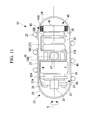
- FIG. 11 is a schematic diagram showing the construction of the capsule endoscope of the capsule endoscope guiding system of FIG. 1 .
- FIG. 12A is a flowchart showing a position detecting method of the capsule endoscope according to the embodiment of the present invention.
- FIG. 12B is a flowchart showing the position detecting method of the capsule endoscope according to the embodiment of the present invention.
- FIG. 13 is a diagram showing an arrangement relationship of a drive coil and a magnetic induction coil.
- FIG. 14 is a diagram showing an arrangement relationship of the drive coil and a sense coil.
- FIG. 15 is a diagram showing another arrangement relationship of the drive coil and the sense coil.
- FIG. 16 is a schematic diagram showing a modification of the capsule endoscope of FIG. 11 .
- FIG. 17 is a partial perspective view showing the construction of an induction magnetic generator in the capsule endoscope of FIG. 11 .
- FIG. 18 is a schematic diagram showing a capsule endoscope guiding system according to a second embodiment of the present invention.
- FIG. 19 is a diagram showing a resonance circuit in the capsule endoscope used for the capsule endoscope guiding system of FIG. 18 .
- FIG. 20 is a schematic diagram showing a medical device guiding system according to a third embodiment of the present invention.
- FIG. 21 is schematic diagram showing the structure of the tip of an insertion portion of the endoscope device of the medical device guiding system of FIG. 20 .
- FIG. 22 is a schematic diagram showing a modification of the medical device guiding system of FIG. 20 .
- FIG. 23 is a schematic diagram showing the structure of the tip of the insertion portion of the endoscope device of the medical device guiding system of FIG. 22 .
- FIG. 24 is a schematic diagram showing a capsule endoscope guiding system according to a fourth embodiment of the present invention.
- FIG. 25 is a graph showing the frequency characteristic of a resonance circuit of another modification of the present invention.
- FIG. 26 is a diagram showing another modification of the capsule endoscope used in the capsule endoscope guiding system of the present invention.
- the medical device of this embodiment is a capsule endoscope 20 .
- FIG. 1 is a diagram showing an outline of a capsule endoscope guiding system (medical device guiding system) 10 according to this embodiment.
- FIG. 2 is a perspective view showing the capsule endoscope guiding system 10 .
- the capsule endoscope guiding system 10 is equipped with a capsule endoscope (capsule medical device) 20 which is administered from a mouth portion or anus of a subject 1 into a body cavity, optically picks up an image of the inner wall surface of a coelomoduct and transmits an image signal wirelessly, a position detecting system 50 for detecting the position of the capsule endoscope 20 , a magnetic induction device 70 for guiding the capsule endoscope 20 on the basis of the detected position of the capsule endoscope 20 and an instruction of a practitioner, and an image display device 80 for displaying the image signal transmitted from the capsule endoscope 20 .
- a capsule endoscope capsule medical device
- the magnetic induction device 70 is equipped with a triaxial Helmholtz coil unit (magnetic generating device or external magnetic generating device) 71 for generating a parallel external magnetic field (rotational magnetic field) M for driving the capsule endoscope 20 , a Helmholtz coil driver 72 for controlling amplification of current to be supplied to the triaxial Helmholtz coil unit 71 , a magnetic field control circuit (magnetic field control device or external magnetic field generating device) 73 for controlling the direction of the external magnetic field M for driving the capsule endoscope 20 , and an input device 74 for outputting the travel direction of the capsule endoscope 20 input by the practitioner to the magnetic field control circuit 73 .
- a triaxial Helmholtz coil unit magnetic generating device or external magnetic generating device
- Helmholtz coil driver 72 for controlling amplification of current to be supplied to the triaxial Helmholtz coil unit 71
- a magnetic field control circuit (magnetic field control device or external magnetic field generating device) 73 for controlling the direction of
- the triaxial Helmholtz coil unit 71 is represented, however, it does not necessarily satisfy the condition of the Helmholtz coil strictly.
- the coil is not circular, but it may be substantially rectangular as shown in FIG. 1 , and the interval between the confronting coils may be out of the condition of the Helmholtz coil insofar as it satisfies the function of this embodiment.
- the triaxial Helmholtz coil unit 71 is formed in a substantially rectangular shape. Furthermore, the triaxial Helmholtz coil unit 71 is equipped with three sets of Helmholtz coils (electromagnets) 71 X, 71 Y, 71 Z which face one another, and each set of the Helmholtz coils 71 X, 71 Y, 71 Z are disposed substantially vertically to the X, Y, Z axes of FIG. 1 .
- the Helmholtz coils disposed substantially vertically to the X, Y, Z axes are represented by Helmholtz coils 71 X, 71 Y, 71 Z respectively in this order.
- the Helmholtz coils 71 X, 71 Y, 71 Z are disposed so as to form a space S having a substantially rectangular parallelepiped therein.
- the space S serves as an operation region (also called as operation region S) of the capsule endoscope 20 , and also it servers as a space in which the subject 1 is placed as shown in FIG. 2 .
- the Helmholtz coil driver 72 has Helmholtz coil drivers 72 X, 72 Y, 72 Z for controlling the Helmholtz coils 71 X, 71 Y, 71 Z, respectively.
- Data of a direction in which the capsule endoscope 20 is currently oriented (the direction of the longitudinal axis R of the capsule endoscope 20 ) is input from a position detecting device 50 A (position information calculator) described later to the magnetic field control circuit 73 , and a travel direction instruction of the capsule endoscope 20 input from the input device 74 by the practitioner is input to the magnetic field control circuit 73 .
- signals for controlling the Helmholtz coil drivers 72 X, 72 Y, 72 Z are output from the magnetic field control circuit 73
- rotational phase data of the capsule endoscope 20 is output from the magnetic field control circuit 73 to the image display device 80 .
- data of current to be supplied to each of the Helmholtz coil drivers 72 X, 72 Y, 72 Z are output from the magnetic field control circuit 73 .
- the magnetic field control circuit 73 receives a magnetic field angle ⁇ from a magnetic field angle calculator 76 described later, and it is set to stop the control signals to the Helmholtz coil drivers 72 X, 72 Y, 72 Z and extinguish an external magnetic field M when the magnetic field angle ⁇ is smaller than a predetermined angle.
- a joy-stick (not shown) is provided as the input device 74 , and the travel direction of the capsule endoscope 20 is indicated by tilting the joy-stick.
- the joy-stick type as described above may be used as the input device 74 , or another type input device such as an input device for indicating the travel direction by pushing the button of the travel direction may be used.
- the position detecting system 50 comprises a drive coil 51 (external alternate magnetic field generating device) which generates an external alternate magnetic field for making a magnetic induction coil 42 A (see FIG. 11 ) described later in the capsule endoscope 20 generate an induced magnetic field, a sense coil (alternate magnetic field detecting device) 52 for detecting the induced magnetic field (alternate magnetic field) generated by the magnetic induction coil 42 A, and a position detecting device 50 A for calculating the position information (position and direction) of the capsule endoscope 20 and controlling the alternate magnetic field formed by the drive coil 51 on the basis of the induced magnetic field detected by the sense coil 52 .
- the position detecting system 50 comprises a magnetic field determining unit 75 (external magnetic field information calculator) for calculating the intensity and direction of the external magnetic field M at the position of the capsule endoscope 20 on the basis of the current data output from the magnetic field control circuit 73 to the Helmholtz coil drivers 72 X, 72 Y, 72 Z and the position data of the capsule endoscope 20 output from the position detecting device 50 A, a magnetic field angle calculator 76 for calculating a magnetic field angle ⁇ corresponding to an intersection angle between the direction of the external magnetic field M and the direction of the magnetic induction coil 42 A (the direction of an alternate magnetic field generated by the magnetic induction coil 42 A) on the basis of the direction of the external magnetic field M at the position of the capsule endoscope 20 calculated by the magnetic field determining unit 75 and the direction of the capsule endoscope 20 calculated by the position detecting device 50 A, and a frequency setting unit 77 for estimating the resonance frequency of the resonance circuit 43 in the capsule endoscope 20 and determining the detection frequency on the basis of the magnetic field
- the position detecting system 50 is provided with the magnetic field determining unit 75 .
- the intensity and direction of the external magnetic field M at the position of the capsule endoscope 20 may be directly received from the magnetic field control circuit 73 by the position detecting system 50 .
- the magnetic field determining unit may be omitted.
- the magnetic field angle calculator 76 for determining the magnetic field angle ⁇ for calculating the intersection angle between the direction of the external magnetic field M and the direction of the induction coil 42 A corresponding to the direction of the capsule endoscope 20 is provided, and the frequency of the external alternate magnetic field generated from the drive coil 51 is determined on the basis of the magnetic field angle and the intensity of the external magnetic field M.
- the operation may be carried out in the frequency setting unit 77 as described below.
- the magnetic field intensity generated from the triaxial Helmholtz coil unit 71 may be controlled to be constant. By this control, the frequency of the external alternate magnetic field generated from the drive coil 51 can be determined on the basis of the magnetic field angle.
- the operation of the frequency setting unit 77 can be simplified. Furthermore, when the restraint of the capsule endoscope 20 by the living body is weak, the magnetic field angle is kept to a value near to 90° at all times. Under such a condition, the frequency of the external alternate magnetic field generated from the drive coil 51 can be determined on the basis of only the intensity of the external magnetic field M without using any information of the magnetic field angle. By this control, the operation of the frequency setting unit 77 can be simplified.
- Equations which are described according to the Biot-Savart law to calculate the intensity and direction of the magnetic field created by the respective Helmholtz coils 71 X, 71 Y, 71 Z at the point (X, Y, Z) in the space S are stored in the magnetic field determining unit 75 , and when the value of current flowing into each of the Helmholtz coils 71 x , 71 Y, 71 Z and the coordinate of the capsule endoscope 20 are input, the intensity and direction of the magnetic field generated by each of the Helmholtz coils 71 X, 71 Y, 71 Z at the position of the capsule endoscope 20 are calculated. Then, by adding the magnetic fields generated by the respective Helmholtz coils 71 X, 71 Y, 71 Z, the intensity and direction of the external magnetic field M generated at the position of the capsule endoscope 20 can be determined.
- each of the Helmholtz coils 71 X, 71 Y, 71 Z forms confronting coil, and thus substantially parallel external magnetic field M having substantially uniform intensity can be formed in the space S in which the capsule endoscope 20 exists. Therefore, only the relational expression representing the relationship between the current flowing into each of the Helmholtz coils 71 X, 71 Y, 71 Z and the magnetic field generated by each of the Helmholtz coils 71 X, 71 Y, 71 Z is stored in the magnetic field determining unit 75 , the current flow flowing in each of the Helmholtz coils 71 X, 71 Y, 71 Z is obtained from the magnetic field control circuit 73 , the intensity of the magnetic field generated by each of the Helmholtz coils 71 X, 71 Y, 71 Z is calculated (the directions of the magnetic fields generated by the respective Helmholtz coils 71 X, 71 Y, 71 Z are constant because of the parallel external magnetic field M), and the intensity and the direction
- the timing at which the current value flowing in each of the Helmholtz coils 71 X, 71 Y, 71 Z is obtained from the magnetic field control circuit is set to the timing at which the position detecting device 50 A carries out the position detection, the intensity and direction of the external magnetic field M can be more accurately determined.
- the relationship of the intensity and direction of the external magnetic field M acting on the capsule endoscope 20 with respect to the time is determined on the basis of past position information of the capsule endoscope 20 , and the respective Helmholtz coil drivers 72 X, 72 Y, 72 Z are controlled to generate the magnetic field in each of the Helmholtz coils 71 X, 71 Y, 71 Z. Therefore, it holds the intensity and direction of the external magnetic field M generated at the position of the capsule endoscope 20 although it is based on the slight past data.
- This direction information may be directly transmitted from the magnetic field control circuit 73 to the magnetic field angle calculator 76 , and the intensity information of the external magnetic field M may be directly transmitted from the magnetic field control circuit 73 to the frequency setting unit 77 , whereby the magnetic field control circuit 73 is brought with the function of the magnetic field determining unit 75 .
- the error of the frequency determined in the frequency setting unit 77 may be slightly increased, however, it brings an effect of miniaturization of the device, simplification of the calculation, etc.
- FIG. 4 shows the result.
- FIGS. 4 to 6 show the frequency characteristics of the resonance circuit 43 detected in the sense coil 52 .
- the output of the sense coil 52 is equal to zero, and the output is peaked at frequencies (peak frequencies) which are slightly displaced backward and forward from the output-zero point. It is apparent that the resonance frequency of the resonance circuit 43 at which the output of the sense coil 52 is equal to zero is shifted in accordance with the intensity of the external magnetic field M and the magnetic field angle ⁇ .
- the frequency characteristic of the resonance circuit varies when the intensity of the external magnetic field M varies, and thus the resonance frequency thereof is shifted. Furthermore, even when the intensity of the external magnetic field M is kept fixed, the frequency characteristic of the resonance circuit 43 varies when the magnetic field angle ⁇ varies, and thus the resonance frequency thereof is shifted.
- the output is rapidly lowered in FIG. 6 because the magnetic induction coil 42 A has an angle to the alternate magnetic field generated by the drive coil 51 , the magnetic flux penetrating through the magnetic induction coil 42 A is reduced, and the induced magnetic field generated by the magnetic induction coil 42 A is reduced.
- FIG. 7 is a graph obtained by plotting the relationship between the peak frequencies of the frequency characteristics of FIGS. 4 to 6 and the intensity of the external magnetic field M.
- FIG. 8 is a graph obtained by plotting the relationship between the peak frequency of the frequency characteristic of FIG. 6 and the magnetic angle ⁇ .
- the frequency setting unit 77 is equipped with a storage unit 78 for storing the resonance frequencies of the resonance circuit 43 shown in FIGS. 4 to 6 and the peak frequencies (detection frequencies) shown in FIGS. 7 and 8 in association with the intensity of the external magnetic field M and the magnetic field angle ⁇ .
- the intensity of the external magnetic field M determined by the magnetic field determining unit 75 and the magnetic field angle ⁇ determined by the magnetic field calculator 76 are input, the data stored in the storage unit 78 are referred to on the basis of the intensity of the external magnetic field M and the magnetic field angle ⁇ , and the corresponding resonance frequency and peak frequency are read out.
- a method of storing data in a matrix form may be first used as a data storing method. That is, the intensity of the external magnetic field M and the magnetic field angle ⁇ are set as two parameters, and the resonance frequency and peak frequency corresponding to each parameter are stored. Accordingly, when the intensity of the external magnetic field M and the magnetic field angle ⁇ are input, the corresponding nearest resonance frequency and peak frequency are selected.
- This method is preferable in that the frequencies can be simply determined, however, the data amount is increased.
- a second method may be used a method of storing, as data, an approximate expression representing the relationship between the intensity of the external magnetic field M and the resonance frequency and the peak frequency every fixed magnetic field angle ⁇ interval.
- an approximate expression representing the relationship between the intensity of the external magnetic field M and the frequency while the interval of the magnetic field angle ⁇ is equal to 5° is created according to the expression 1.
- a 0 , B 0 , C 0 , D 0 , E 0 , A 5 , B 5 , C 5 , D 5 , E 5 , . . . , A 90 , B 90 , C 90 , D 90 , E 90 represent constants, and suffixes represent angles.
- H represents the intensity of the external magnetic field
- f represents the resonance frequency or peak frequency.
- This approximate expression is a polynomial approximate expression created by using the least-square method.
- the frequency setting unit 77 which stores this expression into the storage unit 78 determines that the approximate expression created at the angle nearest to the input magnetic field angle ⁇ is used, and then substitutes the input intensity of the external magnetic field M into the selected expression to determine the resonance frequency and the peak frequency.
- the following approximate expression may be created as an approximate expression representing the relationship of the resonance frequency or the peak frequency, the intensity of the external magnetic field and the magnetic field angle ⁇ .
- f ( ⁇ , H ) ( A ⁇ ⁇ 4 +B ⁇ ⁇ 3 +C ⁇ ⁇ 2 +D ⁇ ⁇ +E ⁇ ) ⁇ ( A H ⁇ H 4 +B H ⁇ H 3 +C H ⁇ H 2 +D H ⁇ H+E H ) [Expression 2]
- a ⁇ , B ⁇ , C ⁇ , D ⁇ , E ⁇ , A H , B H , C H , D H , E H represent constants
- suffix ⁇ represents the magnetic field angle ⁇ obtained form the magnetic field angle calculator
- suffix H represents the intensity of the external magnetic field M obtained from the magnetic field determining unit 75 .
- G is calculated according to the following expression by using the magnetic field angle ⁇ mn , the intensity H mn of the external magnetic field M and the resonance frequency (or the peak frequency) f mn which were experimentally obtained.
- the suffix m represents the measurement
- the suffix n represents the frequency of the measurement (number).
- G ⁇ ( f mn ⁇ f ( ⁇ mn ,H mn )) 2 [Expression 3]
- This expression 3 is partially differentiated by A ⁇ , B ⁇ , C ⁇ , D ⁇ , E ⁇ , A H , B H , C H , D H , E H to obtain differential equations, and simultaneous equations thereof are solved, whereby these constants A ⁇ , B ⁇ , C ⁇ , D ⁇ , E ⁇ , A H , B H , C H , D H , E H can be determined.
- a signal generating circuit 53 for generating alternate current on the basis of the output from the position detecting device 50 A, a drive coil driver 54 for amplifying the alternate current input from the signal generating circuit 53 on the basis of the output from the position detecting device 50 A, and a drive coil selector 55 for supplying the alternate current to the drive coil 51 selected on the basis of the output from the position detecting device 50 A are disposed between the position detecting device 50 A and the drive coil 51 as shown in FIG. 1 .
- the signal generating circuit 53 generates a sine wave signal having a set frequency or a composite wave signal of plural sine wave signals of plural set frequencies.
- a sense coil reception circuit 57 for extracting an amplification value from the alternate current containing position information of the capsule endoscope 20 , etc. from the sense coil 52 on the basis of the output from the position detecting device 50 A and outputting the extracted amplification value to the position detecting device 50 A is disposed between the sense coil 52 and the position detecting device 50 A.
- the resonance frequency set by the frequency setting unit 77 is transmitted to the position detecting device 50 A to make the frequency of the alternate magnetic field output from the signal generating circuit 53 coincident with the resonance frequency.
- the peak frequency determined by the frequency setting unit 77 is also transmitted to the sense coil reception circuit 57 to set the frequency of the alternate magnetic field received by the sense coil 52 to the peak frequency.
- the data may be held as an identification code described in the package of the capsule endoscope so that the code of the package is read out by a reading device in use.
- the data may be described in RFID or a memory of the capsule endoscope.
- FIG. 9 is a schematic diagram showing the cross-section of the capsule endoscope guiding system 10 .
- the drive coils 51 are obliquely disposed at four corners of the upper side (the forward side of the Z-axis) of the substantially rectangular parallelepiped operation region formed by the Helmholtz coils 71 X, 71 Y, 71 Z.
- the drive coils 51 are formed as substantially triangular coils each of which connects the corner portions of the rectangular Helmholtz coils 71 X, 71 Y, 71 Z.
- the drive coils 51 are disposed at the upper side, whereby the interference between the drive coils 51 and the subject 1 can be prevented.
- the drive coils 51 may be designed as substantially triangular coils as described above, or they may be designed in a circular shape or other various shapes.
- the sense coils 52 are formed as air core coils, and they are supported by three planar coil supporting members 58 which are disposed at the inside of the Helmholtz coils 71 X, 71 Y, 71 Z so as to face the drive coils 51 through the operation region S of the capsule endoscope 20 and also face one another in the Y-axis direction.
- Nine sense coils 52 are arranged in a matrix form on one coil supporting member 58 , and the position detecting system 50 is provided with twenty seven sense coils 52 as a whole.
- the sense coils 52 may be located on the same planes as the Helmholtz coils 71 X, 71 Y, 71 Z or at the outside of the Helmholtz coils 71 X, 71 Y, 71 Z, and they may be freely disposed in any arrangement.
- FIG. 10 is a schematic diagram showing the circuit construction of a sense coil reception circuit 57 .
- the sense coil reception circuit 57 comprises high-pass filters (HPF) 59 for removing a low-frequency component of an alternate voltage based on an induced magnetic field containing the position information of the capsule endoscope 20 which is input to the sense coil 52 , pre-amplifiers 60 for amplifying the alternate voltage, band-pass filters (BPF, band limiting unit) 61 for removing a high-frequency component contained in the amplified alternate voltage, amplifiers (AMP) 62 for amplifying the alternate voltage from which the high-frequency component is removed, effective value detecting circuits (True RMS comparators) 63 for detecting the amplitude of the alternate voltage to detect the amplitude value, and outputting the amplitude value, A/D converters 64 for converting the amplitude value to a digital signal, and a memory 65 for temporarily storing the digitalized amplitude value.
- HPF high-pass filters
- the high-pass filter (HPF) 59 also serves to remove a low-frequency signal induced in the sense coil 52 by the rotational magnetic fields generated by the Helmholtz coils 71 X, 71 Y, 71 Z, whereby the position detection system 50 is allowed to operate normally under the state that the magnetic induction device 70 is operated.
- the high-pass filter 59 comprises resistors 67 disposed in a pair of wires 66 A extending from the sense coil 52 , a wire 66 B which connects the pair of wires 66 A and is grounded substantially at the center thereof, and a pair of capacitors 68 disposed so as to face the wire 66 B through the ground point.
- the pre-amplifiers 60 are disposed in a pair of wires 66 A respectively, and the alternate voltages output from the pre-amplifiers 60 are input to one band pass filter 61 .
- the memory 65 temporarily stores the amplitude value obtained from the nine sense coils 52 , and outputs the stored amplitude value to the position detecting device 50 A.
- a common mode filter which can remove noises of common mode may be provided.
- the effective value detection circuits 63 may be used to extract the amplitude value of the alternate voltage, or the amplitude value may be detected by smoothing magnetic information through a rectifying circuit and detecting the voltage.
- phase to the waveform added to the drive coil 51 is varied in accordance with the presence or absence, the position of the magnetic induction coil 42 A.
- This phase variation may be detected by a lock-in amplifier or the like.
- the image display device 80 comprises an image reception circuit 81 for receiving image information transmitted from the capsule endoscope 20 , and a display unit 82 for displaying an image on the basis of the received image information and the signal from the magnetic field control circuit 73 .
- the image reception circuit 81 receives a compressed image signal from the capsule endoscope 20 , and the image signal is output to the display unit 82 .
- the compressed image signal is restored in the image reception circuit 81 or the display unit 82 , and displayed by the display unit 82 .
- the display unit 82 executes the rotation processing on the image signal in the opposite direction to the rotational direction of the capsule endoscope 20 on the basis of the rotational phase data of the capsule endoscope 20 input from the magnetic field control circuit 73 , and then displays the image signal.
- FIG. 11 is a schematic diagram showing the construction of the capsule endoscope 20 .
- the capsule endoscope 20 has an outer package 21 in which various kinds of equipment are accommodated, an image pickup unit 30 for picking up images of the inner wall surface of a coelomoduct of the subject 1 , a battery 39 for driving the image pickup unit 30 , an induced magnetic field generator 40 for generating an alternate magnetic field by the drive coils 51 , and a permanent magnet (magnet) 45 for receiving the external magnetic field M generated by the magnetic induction device 70 and driving the capsule endoscope 20 .
- an image pickup unit 30 for picking up images of the inner wall surface of a coelomoduct of the subject 1
- a battery 39 for driving the image pickup unit 30
- an induced magnetic field generator 40 for generating an alternate magnetic field by the drive coils 51
- a permanent magnet (magnet) 45 for receiving the external magnetic field M generated by the magnetic induction device 70 and driving the capsule endoscope 20 .
- the outer package 21 is constructed by a cylindrical capsule main body (hereinafter referred to as main body) 22 which has a center axis as the longitudinal axis R of the capsule endoscope 20 and through which infrared light is transmitted, a semi-spherical transparent tip portion 23 covering the front end of the main body 22 , and a semi-spherical rear end portion 24 covering the rear end of the main body, and the outer package 21 forms a hermetically-sealed capsule container having a water-tight structure.
- main body 22 which has a center axis as the longitudinal axis R of the capsule endoscope 20 and through which infrared light is transmitted
- a semi-spherical transparent tip portion 23 covering the front end of the main body 22
- a semi-spherical rear end portion 24 covering the rear end of the main body
- a spiral unit (spiral mechanism) 25 is provided on the outer peripheral surface of the main body of the outer package 21 by winding a wire rod having a circular section in a spiral form around the outer peripheral surface with the longitudinal axis R as the center thereof.
- the spiral unit 25 When the permanent magnet 45 receives the rotating external magnetic field M generated by the magnetic induction device 70 and it is rotated, the spiral unit 25 is rotated around the longitudinal axis R together with the main body 22 , so that the rotational motion of the main body 22 around the longitudinal axis R by the spiral unit 25 is converted to the linear motion in a direction along the longitudinal axis R. Therefore, the capsule endoscope 20 can be guided in the longitudinal axis R direction in the lumen.
- the image pickup unit 30 comprises a board 36 A disposed substantially vertically to the longitudinal axis R, an image sensor 31 disposed on a face at the tip portion 23 side of the board 36 A, a lens group 32 for focusing an image of the inner wall surface of the coelomoduct of the subject 1 onto the image sensor 31 , LED (Light Emitting Diode) 33 for illuminating the inner wall surface of the coelomoduct, a signal processor 34 disposed on the face at the rear end portion 24 side of the board 36 A, and a wireless element 35 for transmitting an image signal to the image display device 80 .
- LED Light Emitting Diode
- the signal processor 34 is electrically connected to the battery 39 through boards 36 A, 36 B, 36 C, 36 D and flexible boards 37 A, 37 B, 37 C, electrically connected to the image sensor 31 through the board 36 A, and electrically connected to LED 33 through the board 36 A, the flexible board 37 A and the supporting member 38 .
- the signal processor 34 compresses an image signal obtained by the image sensor 31 , temporarily stores the compressed image signal (into the memory), and transmits the compressed image signal from the wireless element 35 to the outside.
- the signal processor 34 controls ON/OFF of the image sensor 31 and LED 33 on the basis of a signal from a switching unit 46 described later.
- the image sensor 31 converts an image focused through the tip portion 23 and the lens group 32 to an electrical signal (image signal), and outputs it to the signal processor 34 .
- CMOS Complementary Metal Oxide Semiconductor
- CCD Complementary Metal Oxide Semiconductor
- Plural LEDs 33 are arranged on the supporting member 38 disposed at the tip portion 23 side from the board 36 A so as to be spaced from one another in the peripheral direction around the longitudinal axis R.
- the permanent magnet 45 is disposed at the rear end portion 24 side of the signal processor 34 .
- the permanent magnet 45 is disposed or magnetized so as to have a magnetization (magnetic poles) in a direction (for example, in the up-and-down direction of FIG. 5 ) perpendicular to the longitudinal axis R.
- the switching unit 46 disposed on the board 36 B is provided at the rear end portion 24 side of the permanent magnet 45 .
- the switching unit 46 has an infrared sensor 47 , and it is electrically connected to the signal processor 34 through the board 36 B and the flexible board 37 A and also electrically connected to the battery 39 through the boards 36 B, 36 C, 36 D and the flexible boards 37 B, 37 C.
- Plural switching units 46 are arranged at equal intervals in the peripheral direction around the longitudinal axis R, and also the infrared sensor 47 is disposed so as to face the outside in the radial direction.
- the number of switching units 46 is not limited to 4, and it may be any number.
- the battery 39 is disposed at the rear end portion 24 side of the switching unit 46 so as to be sandwiched between the boards 36 C and 36 D.
- the wireless element 35 is disposed on a surface at the rear end portion 24 side of the board 36 D.
- the wireless element 35 is electrically connected to the signal processor 34 through the boards 36 A, 36 B, 36 C, 36 D and the flexible boards 37 A, 37 B, 37 C.
- the induced magnetic field generator 40 disposed at the rear end portion 24 side of the wireless element 35 is constructed by a core member (Magnetic core) 41 formed of ferrite formed in a cylindrical shape whose center axis is substantially coincident with the longitudinal axis R, a magnetic induction coil 42 A disposed on the outer peripheral portion of the core member 41 and a capacitor 42 B (not shown in FIG. 11 ) electrically connected to the magnetic induction coil 42 A and forming the resonance circuit 43 .
- a core member (Magnetic core) 41 formed of ferrite formed in a cylindrical shape whose center axis is substantially coincident with the longitudinal axis R
- a magnetic induction coil 42 A disposed on the outer peripheral portion of the core member 41
- a capacitor 42 B not shown in FIG. 11
- a magnetic material is suitable for the core member 41 , and iron, nickel, Permalloy, cobalt or the like may be used.
- the subject 1 is first in a recumbent position in the space S inside the position detecting system 50 and the magnetic guide device 70 as shown in FIG. 2 (step S 1 ). Subsequently, infrared light is applied to the infrared sensor 47 of the capsule endoscope 20 by an infrared light generating device (not shown), and the power of the capsule endoscope 20 is turned on (omitted in FIG. 12A ). Then, the capsule endoscope 20 is administered into a body cavity of the subject 1 through the mouth portion or anus thereof (step S 2 ).
- the position detecting system 50 is actuated, and the position and direction of the administered capsule endoscope 20 are detected (step S 3 ).
- the Helmholtz coil drivers 72 X, 72 Y, 72 Z are controlled so that the external magnetic field M is generated in the direction perpendicular to the longitudinal axis R of the capsule endoscope 20 (step S 4 ).
- step S 5 It is judged whether the practitioner operates the input device 74 or not (step S 5 ). If the input device 74 is not operated, the steps S 3 to S 5 are repeated. On the other hand, when the input device 74 is operated, it is judge whether the operation concerned is an input for instructing the end or not (step S 6 ). If it is not the end instruction, according to the input from the input device 74 , the direction of the capsule endoscope 20 is changed or the Helmholtz coil drivers 72 X, 72 Y, 72 Z are controlled by the magnetic field control circuit 73 so as to generate the external magnetic field M for rotating the capsule endoscope 20 around the longitudinal axis R (step S 7 ).
- the capsule endoscope 20 which is guided to the neighborhood of an affected site in the coelomoduct of the subject 1 by the magnetic induction device 70 picks up images of the inner wall surface of the coelomoduct during the guidance to the affected site and in the neighborhood of the affected site.
- the data of the inner wall surface of the coelomoduct and the data of the neighborhood of the affected site whose images are picked up are transmitted to the image display device 80 .
- the image display device 80 displays the transmitted images on the display unit 82 .
- the position and direction of the capsule endoscope 20 are calculated by the position detecting device 50 A (step S 9 ), and by the magnetic field determining unit 75 provided to the position detecting system 50 , the intensity and direction of the external magnetic field M are determined on the basis of the position data of the capsule endoscope 20 which are transmitted from the position detecting device 50 A and the current data flowing in the respective Helmholtz coils 71 X, 71 Y, 71 Z for generating the external magnetic field M which are transmitted from the magnetic field control circuit 73 .
- the magnetic field angle calculator 76 calculates the magnetic field angle ⁇ corresponding to the intersection angle between the external magnetic field M and the alternate magnetic field induced by the magnetic induction coil 42 A on the basis of the direction data of the capsule endoscope 20 transmitted from the position detecting device 50 A and the direction data of the external magnetic field M transmitted from the magnetic field determining unit 75 (step S 10 ).
- step S 11 it is judged whether the magnetic field angle ⁇ is smaller than a predetermined angle. If it is smaller, that is, if the intersection angle between the external magnetic field M and the alternate magnetic field is greatly reduced from 90°, the generation of the external magnetic field M is stopped (step S 12 ). Accordingly, the capsule endoscope 20 can be prevented in advance from being rotated under the state that the rotational axis of the external magnetic field M and the longitudinal axis R of the capsule endoscope 20 are greatly displaced from each other.
- the resonance circuit 43 enables the position detection at the original resonance frequency or peak frequency (under the state that no external magnetic field M exists), and thus the accurate position detection can be performed. Therefore, the direction of the external magnetic field M generated when there is an input from the input device 74 again is set to be oriented to the direction perpendicular to the longitudinal axis R of the capsule endoscope (step S 4 ), and after the input from the input device 74 is checked (steps S 5 , S 6 ), the external magnetic field M is rotated (step S 8 ).
- the external magnetic M is rotated under the state that the rotational axis of the external magnetic field M is substantially coincident with the longitudinal axis R of the capsule endoscope 20 , so that the capsule endoscope 20 can be stably rotated with no waggle and properly propelled.
- the direction of the external magnetic field M is changed.
- the direction of the capsule endoscope 20 is changed so that the direction of the permanent magnet 45 is coincident with the direction of the external magnetic field M.
- the direction of the external magnetic field M and the direction of the longitudinal axis R of the capsule endoscope 20 are displaced from the orthogonal state, and the magnetic field angle ⁇ satisfies ⁇ 90°. Therefore, a torque for changing the direction of the capsule endoscope 20 is generated according to this displacement.
- the capsule endoscope 20 changes its direction.
- the magnetic field angle ⁇ is smaller than a predetermined angle, and thus the processing goes to step S 11 again to reset the operation again.
- the resonance frequency and/or the peak frequency stored in the storage unit 78 are read out on the basis of the intensity of the external magnetic field M output from the magnetic field determining unit 75 and the magnetic field angle ⁇ output from the magnetic field angle calculator 76 , and transmitted to the position detecting device 50 A and the sense coil reception circuit 57 (step S 13 ).
- the position detecting device 50 A outputs the above transmitted resonance frequency to the signal generating circuit 53 as the frequency of an alternate signal to be generated.
- the signal generating circuit 53 outputs to the drive coil driver 54 the alternate signal whose frequency is coincident with the resonance frequency transmitted from the position detecting device 50 A. Even when the alternate signal generated by the drive coil driver 54 is slightly displaced from the resonance frequency, some degree of effect can be obtained. For example, when the resonance frequency is equal to 20.04 kHz and the frequency which can be generated by the signal generating circuit 53 is varied every 100 Hz, such as 19.9 kHz, 20 kHz, 20.1 kHz, the frequency generated by the signal generating circuit 53 may be set to 20 kHz. In this case, substantially the same effect as the case where the frequency is accurately conformed with the resonance frequency can be obtained.
- the alternate signal is amplified in the drive coil driver 54 , and output as alternate current to the drive coil selector 55 .
- the amplified alternate current is supplied to the drive coil 51 selected by the position detecting device 50 A in the drive coil selector 55 . Then, the alternate current supplied to the drive coil 51 forms an alternate magnetic field in the operation region S of the capsule endoscope 20 .
- the alternate magnetic field thus formed makes the sense coils 52 and the magnetic induction coil 42 A in the capsule endoscope 20 generates induced electromotive force.
- both of the alternate magnetic field based on the drive coil 51 and the alternate magnetic field induced in the magnetic induction coil 42 A act on the sense coils 52 , and the corresponding alternate voltages occur in the sense coils 52 .
- the magnetic induction coil 42 A forms the resonance circuit 43 together with the capacitor 42 B. Therefore, when the frequency of the alternate magnetic field is coincident with the resonance frequency of the resonance circuit 43 , the induced electromotive force generated in the resonance circuit 43 (magnetic induction coil 42 A) is large, and the formed alternate magnetic field is strong. Furthermore, the core member 41 formed of ferrite having dielectric property is disposed at the center of the magnetic induction coil 42 A, so that magnetic fields can be easily collected at the core member 41 and the induced alternate magnetic field is further strong.
- the alternate voltage generated in the sense coil 52 is input to the sense coil reception circuit 57 , and the amplitude value of the alternate voltage is extracted.
- the low-frequency component contained in the alternate voltage is removed by the high pass filter 59 , and amplified by the pre-amplifier 60 . Thereafter, the high-frequency component is removed by the band pass filter 61 , and amplified by the amplifier 62 .
- the transmission frequency of the band pass filter 61 is adjusted so as to be equal to the peak frequency transmitted from the position detecting device 50 A.
- the amplitude value of the alternate voltage from which unnecessary components are removed as described above is extracted by the effective value detecting circuit 63 .
- the extracted amplitude value is converted to a digital signal by the A/D converter 64 , stored in the memory 65 and then transmitted to the position detecting device 50 A.
- the position detecting device 50 A calculates the position and direction of the capsule endoscope 20 on the basis of the output of each sense coil 52 which is transmitted from the sense coil reception circuit 57 .
- the position detection device 50 A calculates the position and direction of the capsule endoscope 20 by solving simultaneous equations associated with the position and direction of the capsule endoscope 20 and the intensity of magnetic field on the basis of the amplitude of the alternate magnetic field obtained from the selected sense coil 52 .
- step S 14 It is judged whether the end instruction is made from the input device 74 by the practitioner (step S 14 ). If it is not input, the steps S 8 to S 14 are repeated, and if the end instruction is input, the operation is interrupted, and the position detecting operation and the guiding operation are finished.
- the information of the position and direction of the capsule endoscope 20 are used totally six information of the position coordinates of X, Y, Z, the direction of the longitudinal axis of the capsule endoscope 20 (two angles) and the intensity of the induced magnetic field formed by the magnetic induction coil 42 A.
- the number of the sense coils 52 may be set to six or more in this embodiment. However, if it is set to about 10 to 15, the position calculation error can be suppressed to a small value. Furthermore, as a method of selecting the sense coil 52 , the outputs of all the sense coils 52 which are caused by the alternate magnetic field generated by the magnetic field induction coil 42 A may be determined by calculation, and a required number of sense coils 52 having large outputs may be selected.
- the data of the calculated position and direction of the capsule endoscope 20 may be output to other devices or the display unit 82 .
- the position detecting device 50 A selects the drive coil 51 forming the alternate magnetic field and outputs an instruction to the drive coil selector 55 to supply alternate current to the selected drive coil 51 .
- the selection of the drive coil 51 is carried out by using a method of excluding a drive coil 51 with which a line connecting the drive coil 51 and the magnetic induction coil 42 A (the direction of the drive coil 51 ) and the center axial line of the magnetic induction coil 42 A (the longitudinal axis R of the capsule endoscope 20 ) are substantially orthogonal to each other is removed, disposing the direction of the magnetic field acting on the magnetic induction coil 42 A primarily independently and supplying alternate current to any one of three drive coils 51 or plural drive coils as shown in FIG. 14 .
- a method of excluding a drive coil 51 with which the direction of the magnetic field lines formed by the drive coil 51 is substantially orthogonal to the center axial line of the magnetic induction coil 42 A is more effective as a more preferable method.
- the number of drive coils 51 forming the alternate magnetic field may be restricted by using the drive coil selector 55 , or the arrangement number of the drive coils 51 may be set to three from the first drive coil 51 without using the drive coil selector 55 .
- three drive coils 51 may be selected to form alternate magnetic field, or the alternate magnetic field may be generated by all the drive coils 51 as shown in FIG. 15 .
- the switching operation of the drive coils 51 is carried out as a countermeasure to occurrence of such a problem that the alternate magnetic field induced by the magnetic induction coil 42 A would be reduced and thus the precision of the position detection would be reduced if the direction of the alternate magnetic field generated by the drive coil 51 and the direction of the magnetic induction coil 42 A are vertical to each other at the position of the capsule endoscope 20 .
- the direction of the magnetic induction coil 42 A that is, the direction of the capsule endoscope 20 can be known from the output of the position detecting device 50 A. Furthermore, the direction of the alternate magnetic field generated at the position of the capsule endoscope 20 by the drive coil 51 can be determined by the calculation. Accordingly, the intersection angle between the direction of the capsule endoscope 20 and the direction of the alternate magnetic field generated at the position of the capsule endoscope 20 by the drive coil 51 can be determined by the calculation.
- the directions of the alternate magnetic fields at the position of the capsule endoscope 20 which are generated by the drive coils 51 disposed at different positions and in different directions can be respectively determined by the calculation.
- the intersection angle between the direction of the capsule endoscope 20 and the direction of the alternate magnetic field generated at the position of the capsule endoscope 20 by the respective drive coils 51 can be determined by the calculation.
- the drive coil 51 with which the intersection angle between the direction of the capsule endoscope 20 and the direction of the alternate magnetic field generated at the position of the capsule endoscope 20 by the drive coil 51 is in acute-angle relationship with each other, the alternate magnetic field generated from the magnetic induction coil 42 A can be kept large, and an excellent state can be kept to carry out position detection.
- the direction of the alternate magnetic field generated at the position of the capsule endoscope 20 by the drive coil 51 is determined by the calculation. Subsequently, the intersection angle between the direction of the capsule endoscope 20 and the direction of the alternate magnetic field generated at the position of the capsule endoscope 20 by the drive coil 51 is calculated.
- the directions at the position of the capsule endoscope 20 of the alternate magnetic fields generated by the drive coils 51 disposed at different positions and in different directions are respectively calculated.
- the intersection angle between the direction of the capsule endoscope 20 and the direction of the alternate magnetic field generated at the position of the capsule endoscope 20 by each drive coil 51 is calculated.
- the drive coil 51 with which the intersection angle between the direction of the capsule endoscope 20 and the direction of the alternate magnetic field generated at the position of the capsule endoscope 20 by the drive coil 51 have the most acute-angle relationship is selected on the basis of the above calculation results.
- the alternate magnetic field generated by the magnetic induction coil 42 A can be efficiently detected by the sense coils 52 at all times under the condition that an alternate magnetic field which is as large as possible occurs. Therefore, the data amount used for the position calculation of the capsule endoscope 20 (magnetic induction coil 42 A) can be reduced without losing the precision. Accordingly, the calculation amount can be reduced, and the system can be constructed at low cost. There is obtained such an effect that the system speed can be increased, etc.
- two or more drive coils 51 may be selected.
- the alternate magnetic fields generated at the position of the capsule endoscope 20 (the magnetic induction coil 42 A) by all the selected drive coils 51 are calculated, and the outputs of the respective drive coils 51 are adjusted so that the direction of the composite alternate magnetic field and the direction of the capsule endoscope 20 (magnetic induction coil 42 A) are in acute-angle relationship with each other.
- the outputs of the drive coils 51 may be adjusted so that the intensities of the alternate magnetic fields at the position of the capsule endoscope 20 (magnetic induction coil 42 A) generated by the drive coils 51 are constant or converged within some region.
- the alternate magnetic field generated from the magnetic induction coil 42 A can be more stably output. Accordingly, the position detection can be implemented more accurately and more efficiently.
- the practitioner inputs the guide direction of the capsule endoscope 20 to the magnetic field control circuit 73 through the input device 74 .
- the direction and rotational direction of the external magnetic field M applied to the capsule endoscope 20 is determined on the basis of the input guide direction and the direction of the capsule endoscope 20 (longitudinal axis direction) input from the position detecting device 50 A.
- the intensity of the magnetic field generated by each of the Helmholtz coils 71 X, 71 Y, 71 Z necessary to form the direction of the parallel magnetic field is calculated, and the current value required to generate this magnetic field is calculated.
- the data of the current values supplied to the respective Helmholtz coils 71 X, 71 Y, 71 Z are output to the corresponding Helmholtz coil drivers 72 X, 72 Y, 72 Z, and the respective Helmholtz coil drivers 72 X, 72 Y, 72 Z amplify current on the basis of input data, and supply the current to the corresponding Helmholtz coils 71 X, 71 Y, 71 Z.
- the Helmholtz coils 71 X, 71 Y, 71 Z supplied with current generate the magnetic fields corresponding to the respective current values, and these magnetic fields are combined with each other, thereby forming the external magnetic field M having the parallel magnetic field direction determined by the magnetic field control circuit 73 .
- the permanent magnet 45 is mounted in the capsule endoscope 20 , and the attitude of the capsule endoscope 20 (the direction of the longitudinal axis R) is controlled by the force or the torque which are generated when the external magnetic field M acts on the permanent magnet 45 . Furthermore, the rotational period of the external magnetic field M is controlled to range from 0 Hz to about several Hz, and also the rotational direction of the external magnetic field M is controlled, whereby the rotational direction around the longitudinal axis R of the capsule endoscope 20 is controlled and the travel direction and the travel speed of the capsule endoscope 20 are controlled.
- the infrared sensor 47 of the switching unit 46 is first irradiated with infrared light, and the switching unit 46 outputs a signal to the signal processor 34 .
- the signal processor 34 supplies current from the battery 39 to the image sensor 31 , LED 33 , the wireless element 35 and the signal processor 34 itself mounted in the capsule endoscope 20 , and sets these elements to ON-state.
- the image sensor 31 picks up an image of the wall surface of the coelomoduct of the subject 1 illuminated by LED 33 , converts the image to an electrical signal and outputs the electrical signal to the signal processor 34 .
- the signal processor 34 compresses the input image signal, temporarily stores the compressed image signal and outputs it to the wireless element 35 .
- the compressed image signal input to the wireless element 35 is transmitted as electrical waves to the image display device 80 .
- the capsule endoscope 20 is rotated around the longitudinal axis R by the spiral unit 25 disposed on the outer periphery of the outer package 21 , whereby the capsule endoscope 20 can move to the tip portion 23 side or the rear end portion 24 side.
- the moving direction is determined by the rotational direction around the longitudinal axis R and the rotational direction of the spiral unit 25 . Accordingly, the rotational direction around the longitudinal axis R of the capsule endoscope 20 is controlled, whereby the direction of the propelling force acting on the capsule endoscope 20 can be controlled.
- the strength and direction of the rotational magnetic field corresponding to the external magnetic field M acting on the capsule endoscope 20 are varied, and even when the frequency characteristic of the resonance circuit 43 in the capsule endoscope 20 is varied in connection with the variation of the intensity and direction of the external magnetic field M, the resonance frequency and the peak frequency which are pre-stored in the storage unit 78 on the basis of the intensity of the external magnetic field M and the magnetic field angle ⁇ are successively called, and the called peak frequency is set as the frequency to be detected by the sense coil 52 , so that the reduction of the detection sensitivity can be prevented.
- the frequency of the alternate magnetic field generated by the drive coil 51 is also set to the called resonance frequency as described above, and thus the resonance circuit 43 in the capsule endoscope 20 can be kept to the resonance state irrespective of the state of the intensity of the external magnetic field M, etc., so that a larger alternate magnetic field can be generated and the detection sensitivity can be enhanced.
- the capsule medical device 20 can be miniaturized. Or, it is unnecessary to select or adjust the element such as the capacitor 42 B constituting the resonance circuit 43 together with the magnetic induction coil 42 A for the purpose of the adjustment of the resonance frequency, and the production cost of the capsule medical device 20 can be prevented from increasing.
- the band pass filter 61 can limit the band of the output frequency of the sense coil 52 on the basis of the peak frequency transmitted from the position detecting device 50 A. Therefore, the position and direction of the capsule medical device 20 can be calculated on the basis of the outputs of the sense coils 52 of the resonance frequency band, so that the time required for the calculation can be shortened.
- the alternate magnetic fields are made to act on the magnetic induction coil 42 A of the capsule endoscope 20 from three or more directions which are primarily independent of and different from one another. Therefore, the alternate magnetic field can be induced in the magnetic induction coil 42 A by the alternate magnetic field from at least one direction irrespective of the direction of the magnetic induction coil 42 A.
- the magnetic induction coil 42 A can be made to generate the alternate magnetic field at all times irrespective of the direction (longitudinal axis R direction) of the capsule endoscope 20 , the alternate magnetic field can be detected by the sense coil 52 at all times and the position thereof can be accurately detected.
- the sense coils 52 are disposed in different three directions with respect to the capsule endoscope 20 . Therefore, irrespective of the arrangement position of the capsule endoscope 20 , the external magnetic field having a detectable intensity acts on the sense coil 52 disposed at least one direction of the sense coils arranged in the three directions, and thus the alternate magnetic field can be detected by the sense coil 52 at all times.
- the number of the sense coils 52 disposed in the above one direction is equal to nine, and thus sufficient inputs can be obtained so as to calculate totally six information of the X, Y, Z coordinates of the capsule endoscope 20 , the rotational phases around the two axes which are orthogonal to the longitudinal axis R of the capsule endoscope 20 and also perpendicular to each other, and the intensity of the induced magnetization.
- the drive coils 51 and the sense coils 52 are arranged so as to face one another through the operation region of the capsule endoscope 20 . Therefore, the drive coils 51 and the sense coils 52 can be arranged without structurally interfering with each other.
- the direction of the force acting on the permanent magnet 45 can be controlled, and the moving direction of the capsule endoscope 20 can be controlled.
- the position of the capsule endoscope 20 can be detected, and the capsule endoscope 20 can be guided to a predetermined position. Accordingly, on the basis of the position of the detected capsule endoscope 20 , the capsule endoscope 20 can be accurately guided.
- the direction of the external magnetic field occurring inside the Helmholtz coils 71 X, 71 Y, 71 Z can be controlled to a predetermined direction. Therefore, the parallel external magnetic field M in a predetermined direction can be made to act on the capsule endoscope 20 , and the capsule endoscope 20 can be moved in a predetermined direction.
- the space S inside the Helmholtz coils 71 X, 71 Y, 71 Z is a space in which the subject 1 can be disposed, and the drive coils 51 and the sense coils 52 are arranged around the space S. Therefore, the capsule endoscope 20 can be guided to a predetermined position in the body of the subject 1 .
- the image display device 80 executes the processing of rotating the image to be displayed in the rotational direction and opposite direction of the capsule endoscope 20 on the basis of the rotational phase information around the longitudinal axis R of the capsule endoscope 20 . Therefore, irrespective of the rotational phase of the capsule endoscope 20 , the image can be displayed on the display unit 82 as an image which stands still with a predetermined rotational phase at all times, that is, as if the capsule endoscope 20 travels in a direction along the longitudinal axis R without rotating around the longitudinal axis R.
- the practitioner when the practitioner guides the capsule endoscope 20 while viewing the image displayed on the display unit 82 , the practitioner can more easily view the image and more easily guide the capsule endoscope 20 to a desired position when a display image is displayed as an image of a predetermined rotational phase as described above as compared with a case where a display image is displayed as an image which rotates in connection with the rotation of the capsule endoscope 20 .
- the capsule endoscope has the structure shown in FIG. 11 .
- the lens group 32 , LED 33 , the image sensor 31 , the signal processor 34 , the battery 39 , the switching unit 46 , the wireless element 35 and the permanent magnet 45 may be disposed in this order from the tip portion 23 side in the outer package 21 of the capsule endoscope 20 A as shown in FIGS. 16 and 17 .
- the induced magnetism generator 43 A is disposed between the outer package 21 and the battery 39 , etc., and also disposed so as to cover the elements from the supporting member 38 of LED 33 to the battery 39 .
- the induced magnetism generator 43 comprises a cylindrical core member 41 A whose center axis is substantially coincident with the rotational axis R, a magnetic induction coil 42 A disposed on the outer peripheral portion of the core member 41 A, a Permalloy film 41 B disposed between the core member 41 A and the magnetic induction coil 42 A, and a capacitor 42 B (not shown) which is electrically connected to the magnetic induction coil 42 A and forms the resonance circuit 43 .
- the Permalloy film 41 B is formed by designing a magnetic material like sheet film.
- a gap t is formed.
- the intensity of the alternate magnetic field generated in the induced magnetism generator 43 A can be enhanced.
- the resonance frequency and the peak frequency of the resonance circuit 43 are stored in the storage unit 78 .
- only the resonance frequency may be stored and the peak frequency may be determined from the resonance frequency.
- the magnetic core 41 as the magnetic induction coil 42 A is described.
- the variation of the characteristic due to the external magnetic field of the magnetic core 41 is one factor of causing the variation of the resonance frequency of the resonance circuit 43 .
- the same effect could be also achieved if the frequency used in the position detecting system 50 is determined in the frequency setting unit 77 on the basis of the magnetic field angle and the intensity of the external magnetic field M as described with reference to the embodiment.
- the battery may be considered as the magnetic material in the parts of the capsule endoscope 20 .
- the capsule endoscope 20 has the magnet mounted therein and is guided by the external magnetic field.
- the frequency setting unit 77 can determine the frequency used in the position detecting system 50 on the basis of the resonance frequency of the resonance circuit of the capsule endoscope. Therefore, this embodiment can operate. In this case, the effect that the position of the capsule endoscope can be accurately detected can be likewise obtained. In this case, this system operates as a medical device position detecting system.
- the basic construction of the capsule endoscope guiding system 100 according to this embodiment is the same as the capsule endoscope guiding system 10 according to the first embodiment, however, it is different in the construction of a resonance circuit 43 ′ and a position detecting system 50 ′ in a capsule endoscope 20 ′.
- FIG. 17 is a diagram showing the capsule endoscope guiding system 100 of this embodiment schematically.
- the resonance circuit 43 ′ provided in the capsule endoscope 20 ′ constitutes a self-excited oscillation circuit having an amplifier 42 C connected to a power source as shown in FIG. 18 . Accordingly, in this embodiment, the resonance circuit 43 ′ itself generates an alternate magnetic field at a resonance frequency determined on the basis of the inductance of the magnetic induction coil 42 A and the capacitance of the capacitor 42 B by using the energy of the power source.
- the resonance circuit 43 ′ of the capsule endoscope is constructed by the self-excited oscillation circuit, and thus it is unnecessary that an alternate magnetic field for resonating the resonance circuit 43 ′ is supplied from the outside like the first embodiment. Accordingly, as shown in FIG. 17 , the position detecting system 50 ′ is not equipped with the drive coil 51 , the signal generating circuit 53 , the drive coil driver 54 and the drive coil selector 55 which are connected to the position detecting device 50 A.
- a pre-stored frequency is read out in accordance with the intensity of the external magnetic field M and the magnetic field angle ⁇ at the position of the capsule endoscope 20 ′, and fed back from the position detecting device 50 A to the sense coil reception circuit 57 . Therefore, even when the resonance frequency of the self-excited oscillation circuit in the capsule endoscope 20 ′ varies in accordance with the intensity of the external magnetic field M and the magnetic field angle ⁇ , the alternate magnetic field generated by the resonance of the resonance circuit 43 ′ at the resonance frequency after the variation concerned can be detected. Accordingly, the reduction of the detection sensitivity can be prevented.
- the position and direction of the capsule endoscope 20 ′ can be detected with high precision, and thus the capsule endoscope 20 ′ can be properly guided without making the operation thereof unstable.
- the alternate magnetic field generated by the resonance circuit 43 ′ is dependent on the inductance of the magnetic induction coil 42 A and the capacitance of the capacitor 42 B. Therefore, as compared with the first embodiment, the detection sensitivity is lower, however, the guiding system 100 can be more simply constructed because the drive coils 51 , etc. are not required to be provided.
- FIGS. 20 to 21 a medical device guiding system 110 according to a third embodiment of the present invention will be described with reference to FIGS. 20 to 21 .
- the medical device guiding system 110 is a system for guiding an endoscope device having a slender insertion portion 20 ′′ introduced into a body cavity in place of the capsule endoscope 20 of the capsule endoscope guiding system 10 according to the first embodiment.
- the magnetic induction coil 42 A and the capacitor 42 B constituting the same resonance circuit 43 as the first embodiment and the permanent magnet 45 as shown in FIG. 21 .
- the magnetic core 41 is disposed inside the magnetic induction coil 42 A.
- the permanent magnet 45 is disposed so that the magnetic poles are arranged in a direction along the longitudinal axis of the insertion portion 20 ′′.
- the medical device guiding system 110 has substantially the same construction as the guiding system 10 according to the first embodiment. However, it is different in that, instead of the magnetic field control circuit 73 , it is provided with a magnetic field control circuit 73 ′ for controlling formation of an external magnetic field M directed in a desired direction on the basis of an input from the input device 74 . Image information obtained by the image sensor (not shown) disposed at the tip of the insertion portion 20 ′′ is transmitted to the image reception circuit 81 through a cable.
- the generated external magnetic field M acts on the permanent magnet 45 disposed at the tip of the insertion portion 20 ′′, and the tip of the insertion portion 20 ′′ is guided in a direction along the external magnetic field M, whereby the tip of the insertion portion 20 ′′ of the endoscope device can be trained in the desired direction.
- the alternate magnetic field acts on the magnetic induction coil 42 A disposed at the tip of the insertion portion 20 ′′, and the resonance circuit 43 is set to the resonance state, so that a strong alternate magnetic field is generated by the magnetic induction coil 42 A.
- the frequency characteristic of the magnetic induction coil 42 A varies in accordance with the intensity and direction of the external magnetic field M penetrating through the magnetic induction coil 42 A.
- the alternate magnetic field of the resonance frequency read out on the basis of the intensity of the external magnetic field M and the magnetic field angle ⁇ is generated by the drive coil 51 , and also the alternate magnetic field of the read-out peak frequency is detected by the sense coil 52 , whereby the position of the tip of the insertion portion 20 ′′ can be detected without reducing the detection sensitivity.
- the endoscope device is adopted as the medical device.
- a catheter may be applied.
- the closed resonance circuit 43 is disposed at the top of the insertion portion 20 ′′ of the endoscope device.
- a resonance circuit 43 in which the magnetic induction coil 42 A and the capacitor 42 B are connected to wires 42 D led along the insertion portion 20 ′′ in parallel may be adopted as shown in FIGS. 22 and 23 .
- the drive coil selector 55 and the drive coil 51 are not required.
- Reference numeral 54 ′ represents a coil driver for driving the resonance circuit 43 .
- the alternate magnetic field of the detection frequency can be surely generated by the resonance circuit 43 disposed at the tip of the insertion portion 20 ′′ without relying on the magnetic induction.
- the capsule endoscope guiding system 120 is equipped with a planar type magnetic field generating device 71 ′ comprising plural induction coils 121 to 125 arranged on a plane in place of the magnetic field generating device 71 comprising the Helmholtz coils 71 X, 71 Y, 71 Z. Furthermore, the drive coil 51 and the sense coil 52 are arranged so as to face the induction coils 121 to 125 through the capsule endoscope 20 .
- the external magnetic field M having desired intensity and direction can be generated at the position of the capsule endoscope 20 by actuating the planar type magnetic field generating device 71 ′.
- the magnetic field generating device 71 comprising the Helmholtz coils 71 X, 71 Y, 71 Z can generate a uniform external magnetic field M at any position in the space S, however, the planar type magnetic field generating device 71 ′ forms a gradient magnetic field (external magnetic field) M whose intensity and direction vary in accordance with the distance from the induction coils 121 to 125 .
- the resonance circuit 43 is more easily affected by the variation of the frequency characteristic dependently on the position of the capsule endoscope 20 as compared with the first embodiment.
- the frequency characteristic of the resonance circuit 43 is varied, the frequency of the alternate magnetic field detected by the sense coil 52 is set to be coincident with the peak frequency. Therefore, the reduction of the detection sensitivity can be prevented, the position of the capsule endoscope 20 can be detected with high precision, and the capsule endoscope 20 can be stably guided in the body cavity.
- the preset detection frequency may be set as a frequency for position detection according to the frequency characteristic as shown in FIG. 25 .
- the frequency characteristic of the resonance circuit 43 when no external magnetic field M acts is represented by A
- ⁇ a represents a predetermined angle for judging stop of occurrence of the external magnetic field M in step S 10 of FIG. 12B , for example.
- one of two frequencies at which the output variation of the frequency characteristic A is peak and which is in the neighborhood of the frequency at the low frequency side is set as a first measurement frequency f 1
- one of two frequencies at which the output variation of the frequency characteristic C is peak and which is in the neighborhood of the frequency at the high-frequency side is set as a second measurement f 2 . Accordingly, even when the measurement is not carried out while monitoring the external magnetic field M and varying the frequency for detection, the alternate magnetic field which is generated by the resonance circuit 43 can be relatively stably detected until the magnetic field angle ⁇ is equal to ⁇ a.
- the encapsulate endoscope 20 , 20 ′ in which the magnetic poles of the permanent magnet 45 are disposed in the direction orthogonal to the longitudinal axis R is used, and the permanent magnet 45 is moved along the rotating external magnetic field M, whereby the capsule endoscope 20 , 20 ′ is rotated around the longitudinal axis R.
- a capsule endoscope 20 A in which the magnetic poles of the permanent magnet 45 are arranged in the longitudinal axis direction may be adopted. Accordingly, the longitudinal axis R of the capsule endoscope 20 A can be moved in the direction along the external magnetic field M, and thus the external magnetic field M can be used to change the direction of the capsule endoscope 20 A. In this case, the capsule endoscope 20 A is not propelled, and it is committed to the peristaltic motion of a living body or the like.
Abstract
Description
- Patent Citation 1: PCT International Publication No. WO2004/014225 A1 Pamphlet
- Patent Citation 2: Japanese Unexamined Patent Application, Publication No. 2005-121573
- M: external magnetic field
- S: operation region (operation range)
- R: longitudinal axis
- θ: magnetic field angle
- 10, 100, 120: capsule endoscope guiding system (medical device guiding system)
- 20, 20′: capsule endoscope (medical device)
- 20″: insertion portion (medical device)
- 25: spiral unit (spiral mechanism)
- 41, 41A: core member (magnetic core)
- 42A: magnetic induction coil
- 43: resonance circuit
- 43′: self-excited oscillation circuit (resonance circuit)
- 45: permanent magnet (magnet)
- 50, 50′: position detecting system
- 50A: position detecting device (position information calculator)
- 51: drive coil (alternate magnetic field generating device)
- 52: sense coil (alternate magnetic field detecting device)
- 70: magnetic induction device (magnetic field generating device)
- 73: magnetic field control circuit (magnetic field control device)
- 75: magnetic field determining unit (external magnetic field information calculator)
- 76: magnetic field angle determining unit (magnetic field angle calculator)
- 77: frequency setting unit
- 78: storage unit
- 110: medical device guiding system
f(θ,H)=(A θ×θ4 +B θ×θ3 +C θ×θ2 +D θ ×θ+E θ)×(A H ×H 4 +B H ×H 3 +C H ×H 2 +D H ×H+E H) [Expression 2]
G=Σ(f mn −f(θmn ,H mn))2 [Expression 3]
Claims (31)
Applications Claiming Priority (3)
| Application Number | Priority Date | Filing Date | Title |
|---|---|---|---|
| JP2005349178 | 2005-12-02 | ||
| JP2005-349178 | 2005-12-02 | ||
| PCT/JP2006/324191 WO2007064013A1 (en) | 2005-12-02 | 2006-12-04 | Medical device position detection system, medical device guiding system, and medical device position detection method |
Publications (2)
| Publication Number | Publication Date |
|---|---|
| US20090171190A1 US20090171190A1 (en) | 2009-07-02 |
| US9002434B2 true US9002434B2 (en) | 2015-04-07 |
Family
ID=38092343
Family Applications (1)
| Application Number | Title | Priority Date | Filing Date |
|---|---|---|---|
| US12/095,341 Expired - Fee Related US9002434B2 (en) | 2005-12-02 | 2006-12-04 | Medical device position detecting system, medical device guiding system, and position detecting method for medical device |
Country Status (6)
| Country | Link |
|---|---|
| US (1) | US9002434B2 (en) |
| EP (1) | EP1955644B1 (en) |
| JP (1) | JP4796075B2 (en) |
| CN (1) | CN101316545B (en) |
| DE (1) | DE602006021611D1 (en) |
| WO (1) | WO2007064013A1 (en) |
Cited By (6)
| Publication number | Priority date | Publication date | Assignee | Title |
|---|---|---|---|---|
| US9591991B2 (en) | 2013-12-10 | 2017-03-14 | Olympus Corporation | Position detection system |
| US10245118B2 (en) | 2015-10-02 | 2019-04-02 | Elucent Medical, Inc. | Signal tag detection components, devices, and systems |
| US10278779B1 (en) | 2018-06-05 | 2019-05-07 | Elucent Medical, Inc. | Exciter assemblies |
| US10751145B2 (en) | 2015-10-02 | 2020-08-25 | Elucent Medical, Inc. | Signal tag detection components, devices, and systems |
| US11298044B2 (en) | 2016-08-12 | 2022-04-12 | Elucent Medical, Inc. | Surgical device guidance and monitoring devices, systems, and methods |
| US11344382B2 (en) | 2014-01-24 | 2022-05-31 | Elucent Medical, Inc. | Systems and methods comprising localization agents |
Families Citing this family (24)
| Publication number | Priority date | Publication date | Assignee | Title |
|---|---|---|---|---|
| EP2191768A4 (en) * | 2007-09-07 | 2016-08-31 | Olympus Corp | Position sensor, medical device guiding system, position sensing method, and medical device guiding method |
| EP2392251A3 (en) * | 2008-06-19 | 2013-02-06 | Olympus Medical Systems Corporation | Magnetically guiding system and magnetically guiding method |
| JP5415717B2 (en) * | 2008-06-19 | 2014-02-12 | オリンパスメディカルシステムズ株式会社 | Inspection apparatus and magnetic induction system using the same |
| US20110313277A1 (en) * | 2009-02-13 | 2011-12-22 | Koninklijke Philips Electronics N.V. | Method and device for magnetic induction tomography |
| JP5414095B2 (en) * | 2009-03-03 | 2014-02-12 | 富士電子工業株式会社 | Heating coil management device and heating coil management method for high-frequency heating device |
| CN102421349B (en) * | 2009-03-10 | 2015-08-12 | 奥林巴斯医疗株式会社 | Position detecting system and method for detecting position |
| CN102427757B (en) * | 2009-03-16 | 2014-06-18 | 奥林巴斯医疗株式会社 | Position detecting system and position detecting method |
| US8450997B2 (en) | 2009-04-28 | 2013-05-28 | Brown University | Electromagnetic position and orientation sensing system |
| US20110144431A1 (en) * | 2009-12-15 | 2011-06-16 | Rainer Graumann | System and method for controlling use of capsule endoscopes |
| CN102802496B (en) * | 2010-02-18 | 2015-04-01 | 奥林巴斯医疗株式会社 | Position detecting system and position detecting method |
| CN102262167A (en) * | 2011-07-08 | 2011-11-30 | 张峰 | Multi-dimensional displacement acceleration sensor |
| CA2875711C (en) * | 2012-06-13 | 2019-11-05 | Corporation De L'ecole Polytechnique De Montreal | Aggregation and control of magneto-responsive entities |
| CN102743174B (en) * | 2012-06-30 | 2016-06-29 | 安翰光电技术(武汉)有限公司 | A kind of method controlling capsule or probe motion |
| CN105208911B (en) * | 2013-06-05 | 2017-08-18 | 切克-卡普有限公司 | The location estimation of imaging capsule in the gastrointestinal tract |
| CN103876703B (en) * | 2014-04-10 | 2016-09-28 | 重庆金山科技(集团)有限公司 | A kind of capsule endoscope system having motion positions function and capsule endoscope thereof |
| CN103932705B (en) * | 2014-04-29 | 2016-02-17 | 中国人民解放军第三军医大学 | A kind of non-contact magnetic inductive cerebral hemorrhage checkout gear of feature based frequency band |
| WO2017127722A1 (en) * | 2016-01-20 | 2017-07-27 | Lucent Medical Systems, Inc. | Low-frequency electromagnetic tracking |
| CN107144209A (en) * | 2017-05-18 | 2017-09-08 | 北京宏强富瑞技术有限公司 | A kind for the treatment of head position intelligent detection device |
| JP6256962B1 (en) * | 2017-06-21 | 2018-01-10 | 朝日インテック株式会社 | Magnetic orientation / position measuring device |
| US11027096B2 (en) | 2017-08-21 | 2021-06-08 | Lucent Medical Systems, Inc. | Flexible circuit bearing a trackable low-frequency electromagnetic coil |
| US11234769B2 (en) | 2018-03-02 | 2022-02-01 | Lucent Medical Systems, Inc. | Wireless electromagnetic navigational element |
| US11426133B2 (en) | 2018-03-13 | 2022-08-30 | Lucent Medical Systems, Inc. | Externally placed electromagnetic fiducial element |
| CN109755007B (en) * | 2018-12-03 | 2020-11-27 | 北京航空航天大学 | Space four-coil system and miniature octopus robot |
| CN110057363B (en) * | 2019-04-26 | 2020-11-27 | 中国地质大学(武汉) | Robot indoor positioning and autonomous navigation system |
Citations (9)
| Publication number | Priority date | Publication date | Assignee | Title |
|---|---|---|---|---|
| JPH0928661A (en) | 1995-07-17 | 1997-02-04 | Olympus Optical Co Ltd | Endoscope shape sensing system |
| JP2003245243A (en) | 2002-02-22 | 2003-09-02 | Olympus Optical Co Ltd | Shape detector for endoscope |
| WO2004014225A2 (en) | 2002-08-08 | 2004-02-19 | University Of Lausanne | System and method for monitoring and stimulating gastro-intestinal motility |
| JP2004255174A (en) | 2003-02-04 | 2004-09-16 | Olympus Corp | Medical device guiding system |
| JP2005121573A (en) | 2003-10-20 | 2005-05-12 | Japan Science & Technology Agency | Detection method of position and direction of wireless magnetic marker and its system |
| US20050216231A1 (en) * | 2004-03-08 | 2005-09-29 | Isao Aoki | Detecting system of position and posture of capsule medical device |
| JP2005304638A (en) | 2004-04-19 | 2005-11-04 | Olympus Corp | Position/posture detecting system for capsule type medical device |
| WO2006064972A1 (en) * | 2004-12-17 | 2006-06-22 | Olympus Corporation | Position detection system, guidance system, position detection method, medical device, and medical magnetic-induction and position-detection system |
| US7123129B1 (en) * | 1995-08-14 | 2006-10-17 | Intermec Ip Corp. | Modulation of the resonant frequency of a circuit using an energy field |
-
2006
- 2006-12-04 DE DE602006021611T patent/DE602006021611D1/en active Active
- 2006-12-04 US US12/095,341 patent/US9002434B2/en not_active Expired - Fee Related
- 2006-12-04 WO PCT/JP2006/324191 patent/WO2007064013A1/en active Application Filing
- 2006-12-04 CN CN2006800448098A patent/CN101316545B/en not_active Expired - Fee Related
- 2006-12-04 JP JP2007548034A patent/JP4796075B2/en not_active Expired - Fee Related
- 2006-12-04 EP EP06833946A patent/EP1955644B1/en not_active Expired - Fee Related
Patent Citations (9)
| Publication number | Priority date | Publication date | Assignee | Title |
|---|---|---|---|---|
| JPH0928661A (en) | 1995-07-17 | 1997-02-04 | Olympus Optical Co Ltd | Endoscope shape sensing system |
| US7123129B1 (en) * | 1995-08-14 | 2006-10-17 | Intermec Ip Corp. | Modulation of the resonant frequency of a circuit using an energy field |
| JP2003245243A (en) | 2002-02-22 | 2003-09-02 | Olympus Optical Co Ltd | Shape detector for endoscope |
| WO2004014225A2 (en) | 2002-08-08 | 2004-02-19 | University Of Lausanne | System and method for monitoring and stimulating gastro-intestinal motility |
| JP2004255174A (en) | 2003-02-04 | 2004-09-16 | Olympus Corp | Medical device guiding system |
| JP2005121573A (en) | 2003-10-20 | 2005-05-12 | Japan Science & Technology Agency | Detection method of position and direction of wireless magnetic marker and its system |
| US20050216231A1 (en) * | 2004-03-08 | 2005-09-29 | Isao Aoki | Detecting system of position and posture of capsule medical device |
| JP2005304638A (en) | 2004-04-19 | 2005-11-04 | Olympus Corp | Position/posture detecting system for capsule type medical device |
| WO2006064972A1 (en) * | 2004-12-17 | 2006-06-22 | Olympus Corporation | Position detection system, guidance system, position detection method, medical device, and medical magnetic-induction and position-detection system |
Non-Patent Citations (1)
| Title |
|---|
| International Search Report dated Feb. 20, 2007 issued in corresponding PCT Application No. PCT/JP2006/324191. |
Cited By (11)
| Publication number | Priority date | Publication date | Assignee | Title |
|---|---|---|---|---|
| US9591991B2 (en) | 2013-12-10 | 2017-03-14 | Olympus Corporation | Position detection system |
| US11344382B2 (en) | 2014-01-24 | 2022-05-31 | Elucent Medical, Inc. | Systems and methods comprising localization agents |
| US10245118B2 (en) | 2015-10-02 | 2019-04-02 | Elucent Medical, Inc. | Signal tag detection components, devices, and systems |
| US10751145B2 (en) | 2015-10-02 | 2020-08-25 | Elucent Medical, Inc. | Signal tag detection components, devices, and systems |
| US11135034B2 (en) | 2015-10-02 | 2021-10-05 | Elucent Medical, Inc. | Signal tag detection components, devices, and systems |
| US11786333B2 (en) | 2015-10-02 | 2023-10-17 | Elucent Medical, Inc. | Signal tag detection components, devices, and systems |
| US11298044B2 (en) | 2016-08-12 | 2022-04-12 | Elucent Medical, Inc. | Surgical device guidance and monitoring devices, systems, and methods |
| US10278779B1 (en) | 2018-06-05 | 2019-05-07 | Elucent Medical, Inc. | Exciter assemblies |
| US11185375B2 (en) | 2018-06-05 | 2021-11-30 | Elucent Medical, Inc. | Exciter assemblies |
| US11540885B2 (en) | 2018-06-05 | 2023-01-03 | Elucent Medical, Inc. | Orthogonally isolated exciter with field steering |
| US11666391B2 (en) | 2018-06-05 | 2023-06-06 | Elucent Medical, Inc. | Exciter assemblies |
Also Published As
| Publication number | Publication date |
|---|---|
| EP1955644A1 (en) | 2008-08-13 |
| EP1955644B1 (en) | 2011-04-27 |
| WO2007064013A1 (en) | 2007-06-07 |
| JP4796075B2 (en) | 2011-10-19 |
| CN101316545B (en) | 2010-11-10 |
| US20090171190A1 (en) | 2009-07-02 |
| JPWO2007064013A1 (en) | 2009-05-07 |
| CN101316545A (en) | 2008-12-03 |
| DE602006021611D1 (en) | 2011-06-09 |
| EP1955644A4 (en) | 2010-02-24 |
Similar Documents
| Publication | Publication Date | Title |
|---|---|---|
| US9002434B2 (en) | Medical device position detecting system, medical device guiding system, and position detecting method for medical device | |
| JP5030392B2 (en) | Medical device position detection system and medical device guidance system | |
| KR100990287B1 (en) | Position detection system | |
| US20070244388A1 (en) | Position Detection System, Guidance System, Position Detection Method, Medical Device, and Medical Magnetic-Induction and Position-Detection System | |
| JP4679200B2 (en) | Capsule type medical device position detection system, capsule type medical device guidance system, and capsule type medical device position detection method | |
| JP4709594B2 (en) | Magnetic guidance medical system | |
| US8032320B2 (en) | Position detection system and position detection method | |
| JP4869040B2 (en) | Position detection system and medical device guidance system | |
| JP4868808B2 (en) | Medical device and medical device system | |
| CN100469310C (en) | Position detection system for a medical device and medical-device guidance system | |
| WO2005063121A1 (en) | System for sensing position in subject | |
| JPH0928662A (en) | Endscope shape sensing system | |
| JP2005192631A (en) | Subject interior position detecting system | |
| EP3165156B1 (en) | Medical device locating system | |
| JP5269348B2 (en) | Position detection system and method of operating the position detection system | |
| JP2010000203A (en) | Inspection apparatus and magnetically guiding system using the same |
Legal Events
| Date | Code | Title | Description |
|---|---|---|---|
| AS | Assignment |
Owner name: OLYMPUS CORPORATION, JAPAN Free format text: ASSIGNMENT OF ASSIGNORS INTEREST;ASSIGNORS:UCHIYAMA, AKIO;KIMURA, ATSUSHI;SATO, RYOJI;AND OTHERS;REEL/FRAME:021013/0374 Effective date: 20080522 |
|
| STCF | Information on status: patent grant |
Free format text: PATENTED CASE |
|
| AS | Assignment |
Owner name: OLYMPUS CORPORATION, JAPAN Free format text: CHANGE OF ADDRESS;ASSIGNOR:OLYMPUS CORPORATION;REEL/FRAME:039344/0502 Effective date: 20160401 |
|
| FEPP | Fee payment procedure |
Free format text: MAINTENANCE FEE REMINDER MAILED (ORIGINAL EVENT CODE: REM.); ENTITY STATUS OF PATENT OWNER: LARGE ENTITY |
|
| LAPS | Lapse for failure to pay maintenance fees |
Free format text: PATENT EXPIRED FOR FAILURE TO PAY MAINTENANCE FEES (ORIGINAL EVENT CODE: EXP.); ENTITY STATUS OF PATENT OWNER: LARGE ENTITY |
|
| STCH | Information on status: patent discontinuation |
Free format text: PATENT EXPIRED DUE TO NONPAYMENT OF MAINTENANCE FEES UNDER 37 CFR 1.362 |
|
| FP | Lapsed due to failure to pay maintenance fee |
Effective date: 20190407 |