EP1540772B1 - Electric connecting device - Google Patents
Electric connecting device Download PDFInfo
- Publication number
- EP1540772B1 EP1540772B1 EP03753396A EP03753396A EP1540772B1 EP 1540772 B1 EP1540772 B1 EP 1540772B1 EP 03753396 A EP03753396 A EP 03753396A EP 03753396 A EP03753396 A EP 03753396A EP 1540772 B1 EP1540772 B1 EP 1540772B1
- Authority
- EP
- European Patent Office
- Prior art keywords
- current
- contact elements
- data
- electrical connecting
- connecting device
- Prior art date
- Legal status (The legal status is an assumption and is not a legal conclusion. Google has not performed a legal analysis and makes no representation as to the accuracy of the status listed.)
- Expired - Lifetime
Links
Images

Classifications
-
- H—ELECTRICITY
- H01—ELECTRIC ELEMENTS
- H01R—ELECTRICALLY-CONDUCTIVE CONNECTIONS; STRUCTURAL ASSOCIATIONS OF A PLURALITY OF MUTUALLY-INSULATED ELECTRICAL CONNECTING ELEMENTS; COUPLING DEVICES; CURRENT COLLECTORS
- H01R13/00—Details of coupling devices of the kinds covered by groups H01R12/70 or H01R24/00 - H01R33/00
- H01R13/62—Means for facilitating engagement or disengagement of coupling parts or for holding them in engagement
- H01R13/6205—Two-part coupling devices held in engagement by a magnet
-
- H—ELECTRICITY
- H01—ELECTRIC ELEMENTS
- H01R—ELECTRICALLY-CONDUCTIVE CONNECTIONS; STRUCTURAL ASSOCIATIONS OF A PLURALITY OF MUTUALLY-INSULATED ELECTRICAL CONNECTING ELEMENTS; COUPLING DEVICES; CURRENT COLLECTORS
- H01R13/00—Details of coupling devices of the kinds covered by groups H01R12/70 or H01R24/00 - H01R33/00
- H01R13/02—Contact members
- H01R13/22—Contacts for co-operating by abutting
- H01R13/24—Contacts for co-operating by abutting resilient; resiliently-mounted
Definitions
- the invention relates to an electrical connection device according to the closer defined in the preamble of claim 1.
- a connecting device of this type is in the WO 9508910 A1 described.
- the present invention has for its object to further improve the previously known electromechanical connection device, in particular for mass production and for a variety of contact connections to make even more appropriate.
- this object is achieved in that a plurality of contact elements of at least one of the two devices are arranged side by side in a grid-shaped configuration, that the contact elements used in the grid-shaped configuration are elastically mounted, and that the grid-shaped configuration on the side facing away from the contact elements a pressing bridge is applied.
- the arrangement of the contact elements of at least one device in the grid-shaped configuration can be created in a confined space a plurality of contact connections.
- the contact elements such as letters of a printing press are arranged side by side, wherein the length can be chosen practically arbitrary.
- Due to the elastic mounting the individual contact elements are freely movable from each other, resulting in optimal contact connections with surface contact.
- the pressing bridge also ensures a perfect surface contact due to the common storage or support of the contact elements on its back.
- the required elasticity for the contact elements can be achieved in a very advantageous embodiment of the invention in that the press bridge is formed elastically. Through an elastic pressing bridge tolerance inaccuracies can be compensated in addition to a very good surface contact. At the same time the pressure is evenly distributed to the individual contact elements.
- the contact elements may be at least partially embedded in an elastic sheath.
- the device according to the grid-shaped skeleton can be extended as desired, much like typographic letters.
- the power or data generator device and the power take-off or data pickup each with Magnet bodies are provided, wherein the magnetic body of the power take-off or data pickup device are arranged opposite to the magnetic bodies of the current generator or data-generating device.
- the device according to the invention can be a pinpoint surface contact, even blind, achieve a very short distance and tolerated by larger tolerances of the parts to be electrically connected.
- the grid-shaped configuration is formed by a skeleton, wherein the skeleton can have at least approximately a meandering shape running with right-angled turns.
- a grid-shaped skeleton can be formed practically by the meter, which can be cut to length in any desired length.
- the contact elements are then inserted and provided in an advantageous manner by injection molding with the elastic sheath, wherein the individual meanders can be filled in accordance with the injection molding.
- two contact elements of the other device are also connected to each other with a conductive bridge part.
- a significantly larger contact area is created, whereby even higher currents can be transmitted at this point.
- the two devices can be interconnected in any other way, e.g. a non-positive or positive connection with or without locks.
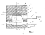
- FIGS. 1 and 2 each show a power or data supply device 1 with a housing 2, in which a plurality of juxtaposed as surface contacts contact elements 3 are arranged.
- a plurality of magnetic body 4 in the form of iron cores or magnets are arranged at a distance from each other.
- a current collection or data removal device 5 with a slave housing 6 is arranged opposite the current or data supply device 1 such that magnets or magnetic bodies 7 which are arranged in the slave housing 6, the magnetic bodies 4, which are arranged in the encoder housing 2 , lie opposite.
- magnets or magnetic bodies 7 which are formed as magnets, and the magnetic bodies 4 as iron cores, it is not necessary to pay attention to a mutual pole. If the magnetic bodies 4 are also designed as magnets, it must be ensured that oppositely directed poles are arranged opposite one another.
- the magnets 7 can be additionally sheathed with an iron sheath 8, thus resulting in a Magnetkrafterhöhung.
- Such embodiments of magnets are well known, which is why will not be discussed here in detail.
- a flow device 1 and a power take-off device 5 will be discussed below.
- the two devices are also suitable for data transmission in the sense of a data-generating device and a data-picking device.
- Magnetic bodies generally designate magnets, magnetizable parts or magnetic parts which react magnetically under the influence of a magnet. It is only essential that the magnetic body 4 of the current generator unit 1 and the current collecting device 5 cooperate in such a way that a magnetic force force results on both parts through a magnetic field.
- the power take-off device 5 is likewise provided with contact elements 9 in the form of surface contacts, which are arranged in the slave housing 6 next to one another in such a way that, when the current-carrying device 1 is connected to the current-collecting device 5, they are respectively arranged opposite the contact elements 3 of the current transmitter unit 1.
- FIGS. 1 and 2 each show the position shortly before contacting the power supply device 1 with the current collection device 5 and thus shortly before a contact connection between the contact elements 3 and 9.
- the contact elements 3 of the current-carrying device 1 are arranged in a grid-shaped configuration in the form of a grid-shaped skeleton 10 in its recesses.
- the grid-shaped frame 10 has a meandering shape with rectangular turns, wherein the contact elements 3 each inserted in a meander or a recess between two ribs 11 and 12, preferably clamped. Due to the meandering shape, a gap 13 results in each case corresponding to the rear side on the next meander with the next contact element 3, by means of which a mobility of the contact elements 3 is provided. In the front meander, which are facing the current collection device 5, the contact elements 3 are clamped.
- the contact elements 3 are each surrounded in the front region by an elastic sheath 14, which extends to just before the contact surfaces 15 of each contact element 3.
- the elastic wrap 14 may be e.g. be introduced or introduced as plastic by injection molding.
- the elastic covering may also be applied in other ways, e.g. in a prefabricated manner, in which case the contact elements are introduced into the plastic accordingly. Again, any lengths of the grid-shaped ridges formed in this way are possible.
- the grid-shaped frame 10 is in a manner not shown, for example by gluing, with a press bridge 16th connected on its back.
- a grid-shaped skeleton instead of a grid-shaped skeleton, other embodiments may of course be provided within the scope of the invention. It is only essential that a plurality of contact elements 3 are arranged like a grid in succession in an elastic envelope.
- the pressing bridge 16 may be formed elastically and slightly concave as a rubber bridge and is arranged correspondingly in the encoder housing 12 between the two magnetic bodies 4, whereby it extends over the entire length of the grid-shaped skeleton 10.
- the elastic sheath 14 By the elastic sheath 14, the air gaps 12 and the pressing bridge 16, a secure surface contact for all contact elements 3 with the contact elements 9 of the current collection device 5 is achieved when connecting the power supply device 1 with the current collection device 5.
- the elastic sheath 14 can also provide a moisture or water-tight connection. At the same time it serves as a corset for the contact elements 3 while maintaining elasticity.
- the contact elements 3 of the current-carrying device 1 have been described as being arranged elastically in the grid-shaped frame 10.
- the contact elements 3 of the power supply device 1 are fixedly arranged in the transmitter housing 2.
- the contact elements 9, as well as the contact elements 3, in the form of thin disks with lateral extensions 17 may be formed.
- About the lateral extensions 17 then takes place via supply and discharge lines 18, the power supply or power transmission to a consumer, not shown.
- the grid-shaped frame 10 may be formed of a resilient plastic part.
- brass parts possibly silver plated, can be used as simple stamped parts.
- the current-carrying device 1 can be provided with one or more conical recesses 19, at whose lower end a respective magnetic body 4 is located.
- the current collection device 5 has one or more conical extensions 20, which are adapted to the cone angle of the conical recesses 19.
- each cone-like extension 20 is in each case a magnetic body 7.
- the cone-like extensions 20 are introduced in accordance self-centering in the cone-like recesses 19, wherein at the end of the introduction, the magnetic body 4 and 7 lie on each other and thereby the contact connections between the contact elements 3 and 9 stable and make sure. As a result of this configuration, a "blind" contacting of the contact elements 3 and 9 is achieved without possibility of error.
- two adjacent contact elements 3 can be connected to one another by a conductive contact bridge 21. (see dashed line in FIG Fig. 1 ). The same applies then to the contact elements 9 cooperating therewith.
- a contact bridge 21 can also be used for cases in which the same output currents or vice versa are to be forwarded from a common input current to two (or more, for longer contact bridges).
- each magnetic body 4 and 7 is composed of a plurality of individual magnetic particles of different polarity, wherein the opposing magnetic bodies 7 and 4 are each arranged opposite to each other.
- coded is meant that each magnetic body is composed of a plurality of individual magnetic particles of different polarity, wherein the opposing magnetic bodies 7 and 4 are each arranged opposite to each other.
- Such a coding is for example from the WO 01/03249 A1 in Fig. 3 can be seen.
- magnets coded in this way are described. In this way, a contact connection can only take place when the correctly coded magnets meet.
- the magnetic body 4 and 7 can also be omitted in case of need and after setting up the power take-off or data collection device to the power or data supply device, a connection or holding force between the two devices can also be performed in other ways, such as locks or latches.
Abstract
Description
Die Erfindung betrifft eine elektrische Verbindungsvorrichtung nach der im Oberbegriff von Anspruch 1 näher definierten Art.The invention relates to an electrical connection device according to the closer defined in the preamble of
Eine Verbindungsvorrichtung dieser Art ist in der
Durch die elastische Anordnung der Kontaktelemente wenigstens einer Einrichtung lassen sich auch mehrere Kontakte optimal zueinander ausrichten und ein sehr guter Flächenkontakt herstellen. Auf diese Weise lassen sich auch höhere Amperezahlen übertragen bzw. weiterleiten.Due to the elastic arrangement of the contact elements of at least one device, it is also possible to optimally align a plurality of contacts with one another and to produce a very good surface contact. In this way, even higher ampere numbers can be transmitted or forwarded.
Der vorliegenden Erfindung liegt die Aufgabe zugrunde, die vorbekannte elektromechanische Verbindungsvorrichtung weiter zu verbessern, insbesondere für eine Serienfertigung und für eine Vielzahl von Kontaktverbindungen noch geeigneter zu machen.The present invention has for its object to further improve the previously known electromechanical connection device, in particular for mass production and for a variety of contact connections to make even more appropriate.
Erfindungsgemäß wird diese Aufgabe dadurch gelöst, dass eine Vielzahl von Kontaktelementen wenigstens einer der beiden Einrichtungen nebeneinander in einer rasterförmigen Ausgestaltung angeordnet sind, dass die in die rasterförmige Ausgestaltung eingesetzten Kontaktelemente elastisch gelagert sind, und dass die rasterförmige Ausgestaltung auf der von den Kontaktelementen abgewandten Seite an einer Pressbrücke anliegt.According to the invention this object is achieved in that a plurality of contact elements of at least one of the two devices are arranged side by side in a grid-shaped configuration, that the contact elements used in the grid-shaped configuration are elastically mounted, and that the grid-shaped configuration on the side facing away from the contact elements a pressing bridge is applied.
Durch die Anordnung der Kontaktelemente wenigstens einer Einrichtung in der rasterförmigen Ausgestaltung lassen sich auf engstem Raum eine Vielzahl von Kontaktverbindungen schaffen. Praktisch sind die Kontaktelemente wie Lettern einer Druckerpresse nebeneinander angeordnet, wobei die Länge praktisch beliebig gewählt werden kann. Durch die elastische Lagerung sind die einzelnen Kontaktelemente frei voneinander beweglich, wodurch sich optimale Kontaktverbindungen mit Flächenberührung ergeben. Die Pressbrücke sorgt ebenfalls für einen einwandfreien Flächenkontakt aufgrund der gemeinsamen Lagerung bzw. Abstützung der Kontaktelemente auf ihrer Rückseite. Die erforderliche Elastizität für die Kontaktelemente kann in einer sehr vorteilhaften Ausgestaltung der Erfindung dadurch erreicht werden, dass die Pressbrücke elastisch ausgebildet ist. Durch eine elastische Pressbrücke können neben einem sehr guten Flächenkontakt auch Toleranzungenauigkeiten ausgeglichen werden. Gleichzeitig wird dabei der Druck gleichmäßig auf die einzelnen Kontaktelemente verteilt.The arrangement of the contact elements of at least one device in the grid-shaped configuration can be created in a confined space a plurality of contact connections. Practically, the contact elements such as letters of a printing press are arranged side by side, wherein the length can be chosen practically arbitrary. Due to the elastic mounting the individual contact elements are freely movable from each other, resulting in optimal contact connections with surface contact. The pressing bridge also ensures a perfect surface contact due to the common storage or support of the contact elements on its back. The required elasticity for the contact elements can be achieved in a very advantageous embodiment of the invention in that the press bridge is formed elastically. Through an elastic pressing bridge tolerance inaccuracies can be compensated in addition to a very good surface contact. At the same time the pressure is evenly distributed to the individual contact elements.
Zusätzlich oder alternativ können die Kontaktelemente wenigstens teilweise in einer elastischen Umhüllung eingebettet sein.Additionally or alternatively, the contact elements may be at least partially embedded in an elastic sheath.
Im Bedarfsfalle lässt sich die Vorrichtung entsprechend dem rasterförmigen Gerippe beliebig verlängern, ähnlich wie Schriftdrucklettern.If necessary, the device according to the grid-shaped skeleton can be extended as desired, much like typographic letters.
In einer vorteilhaften Ausgestaltung der Erfindung kann vorgesehen sein, dass die Strom- oder Datengebereinrichtung und die Stromabnahme- oder Datenabnahmeeinrichtung jeweils mit Magnetkörpern versehen sind, wobei die Magnetkörper der Stromabnahme- oder Datenabnahmeeinrichtung gegenüberliegend zu den Magnetkörpern der Stromgeber- oder Datengebereinrichtung angeordnet sind.In an advantageous embodiment of the invention can be provided that the power or data generator device and the power take-off or data pickup each with Magnet bodies are provided, wherein the magnetic body of the power take-off or data pickup device are arranged opposite to the magnetic bodies of the current generator or data-generating device.
Mit der erfindungsgemäßen Vorrichtung lässt sich ein punktgenaues flächenförmiges Kontaktieren, auch blind, auf sehr kurzer Strecke und unter Duldung von größeren Toleranzen der elektrisch zu verbindenden Teile erreichen.With the device according to the invention can be a pinpoint surface contact, even blind, achieve a very short distance and tolerated by larger tolerances of the parts to be electrically connected.
In einer vorteilhaften konstruktiven Ausgestaltung kann vorgesehen sein, dass die rasterförmige Ausgestaltung durch ein Gerippe gebildet ist, wobei das Gerippe wenigstens annähernd eine mit rechtwinkligen Windungen verlaufende Mäanderform aufweisen kann.In an advantageous structural embodiment, it can be provided that the grid-shaped configuration is formed by a skeleton, wherein the skeleton can have at least approximately a meandering shape running with right-angled turns.
Durch die erfindungsgemäße Mäanderform lässt sich praktisch als Meterware ein rasterförmiges Gerippe bilden, welches entsprechend in beliebiger Länge abgelängt werden kann. In die einzelnen Mäander werden dann die Kontaktelemente eingeschoben und in vorteilhafter Weise im Spritzgussverfahren mit der elastischen Umhüllung versehen, wobei die einzelnen Mäander entsprechend mit dem Spritzguss aufgefüllt werden können. Man kann die nach hinten offenen Mäander jedoch auch freilassen, womit durch den damit vorliegenden Luftspalt eine Erhöhung der Elastizität erreicht wird. Wenn man die Mäanderbreite dabei geringfügig enger macht, als die Dicke der Kontaktelemente, dann werden diese durch Klemmwirkung sicher in den nach vorne ragenden Mäandern gehalten.As a result of the meandering mold according to the invention, a grid-shaped skeleton can be formed practically by the meter, which can be cut to length in any desired length. In the individual meanders, the contact elements are then inserted and provided in an advantageous manner by injection molding with the elastic sheath, wherein the individual meanders can be filled in accordance with the injection molding. However, it is also possible to leave open the meander which is open to the rear, thus increasing the elasticity due to the air gap therewith. If you make the meander width slightly narrower than the thickness of the contact elements, then they are held by clamping action safely in the forward projecting meanders.
Zur Flächenkontaktvergrößerung kann vorgesehen sein, dass zwei nebeneinander liegende Kontaktelemente durch ein leitendes Brückenteil miteinander verbunden sind.For surface contact enlargement can be provided that two adjacent contact elements are interconnected by a conductive bridge part.
Selbstverständlich werden in diesem Falle auch zwei Kontaktelemente der jeweils anderen Einrichtung ebenfalls mit einem leitenden Brückenteil miteinander verbunden. Auf diese Weise wird eine deutlich größere Kontaktfläche geschaffen, wodurch an dieser Stelle noch höhere Ströme übertragen werden können.Of course, in this case, two contact elements of the other device are also connected to each other with a conductive bridge part. In this way, a significantly larger contact area is created, whereby even higher currents can be transmitted at this point.
Anstelle einer Verbindung der Strom- oder Datengebereinrichtung mit der Stromabnahme-.oder Datenabnahmeeinrichtung über die Magnetkörper durch Erzeugung einer magnetischen Haftkraft können die beiden Einrichtungen selbstverständlich auch auf beliebig andere Weise miteinander verbunden werden, wie z.B. eine kraft- oder formschlüssige Verbindung mit oder ohne Verriegelungen.Of course, instead of connecting the power or data-generating device to the power take-off device via the magnetic bodies by generating a magnetic force, the two devices can be interconnected in any other way, e.g. a non-positive or positive connection with or without locks.
Vorteilhafte Weiterbildungen und Ausgestaltungen ergeben sich aus den übrigen Unteransprüchen und aus dem nachfolgend anhand der Zeichnung prinzipmäßig beschriebenen Ausführungsbeispiel.Advantageous developments and refinements emerge from the remaining dependent claims and from the exemplary embodiment described in principle below with reference to the drawing.
Es zeigt:
- Fig. 1
- einen Längsschnitt durch die erfindungsgemäße elektrische Verbindungsvorrichtung nach der Linie I-I der
Fig. 2 ; - Fig. 2
- einen Querschnitt durch die erfindungsgemäße elektrische Verbindungsvorrichtung nach der
Fig. 1 nach der Linie II-II; und
- Fig. 1
- a longitudinal section through the inventive electrical connection device according to the line II of
Fig. 2 ; - Fig. 2
- a cross section through the electrical connecting device according to the invention according to the
Fig. 1 after the line II-II; and
Die
Für eine elektrische Verbindung wird eine Stromabnahme- oder Datenabnahmeeinrichtung 5 mit einem Nehmergehäuse 6 derart der Strom- oder Datengebereinrichtung 1 gegenüberliegend angeordnet, dass Magnete oder Magnetkörper 7, die in dem Nehmergehäuse 6 angeordnet sind, den Magnetkörpern 4, die in dem Gebergehäuse 2 angeordnet sind, gegenüber liegen. Wenn die Magnetkörper 7 als Magnete ausgebildet sind, und die Magnetkörper 4 als Eisenkerne, ist es nicht erforderlich, auf eine Gegenpoligkeit zu achten. Falls die Magnetkörper 4 ebenfalls als Magnete ausgebildet sind, ist dafür zu sorgen, dass jeweils entgegengesetzt gerichtete Pole gegenüberliegend angeordnet werden.For an electrical connection, a current collection or
Zur Verstärkung der Magnetkraft können die Magnete 7 zusätzlich noch mit einem Eisenmantel 8 ummantelt werden, damit sich eine Magnetkrafterhöhung ergibt. Derartige Ausgestaltungen von Magneten sind allgemein bekannt, weshalb hier nicht näher darauf eingegangen wird.To strengthen the magnetic force, the
Zur Vereinfachung wird nachfolgend nur von einer Strömgebereinrichtung 1 und einer Stromabnahmeeinrichtung 5 gesprochen. Selbstverständlich sind die beiden Einrichtungen auch für eine Datenübertragung im Sinne einer Datengebereinrichtung und einer Datenabnahmeeinrichtung geeignet.For the sake of simplicity, only a
Mit Magnetkörper werden ganz allgemein Magnete, magnetisierbare Teile oder magnetische Teile bezeichnet, welche unter dem Einfluss eines Magneten magnetisch reagieren. Wesentlich ist lediglich, dass die Magnetkörper 4 der Stromgebereinheit 1 und der Stromabnahmeeinrichtung 5 derart zusammenwirken, dass sich eine Magnethaftkraft auf beide Teile durch ein magnetisches Feld ergibt.Magnetic bodies generally designate magnets, magnetizable parts or magnetic parts which react magnetically under the influence of a magnet. It is only essential that the
Die Stromabnahmeeinrichtung 5 ist ebenfalls mit Kontaktelementen 9 in Form von Flächenkontakten versehen, welche in dem Nehmergehäuse 6 derart nebeneinander angeordnet sind, dass sie bei einer Verbindung der Stromgebereinrichtung 1 mit der Stromabnahmeeinrichtung 5 jeweils den Kontaktelementen 3 der Stromgebereinheit 1 gegenüberliegend angeordnet sind.The power take-off
Die
Die Kontaktelemente 3 der Stromgebereinrichtung 1 sind in einer rasterförmigen Ausgestaltung in Form eines rasterförmigen Gerippes 10 in dessen Aussparungen angeordnet. Das rasterförmige Gerippe 10 weist eine Mäanderform mit rechtwinkligen Windungen auf, wobei die Kontaktelemente 3 jeweils in einem Mäander bzw. einer Aussparung zwischen zwei Rippen 11 und 12 eingelegt, vorzugsweise eingeklemmt, werden. Aufgrund der Mäanderform ergibt sich jeweils zu dem nächsten Mäander mit dem nächsten Kontaktelement 3 entsprechend rückseitig ein Spalt 13, durch den eine Beweglichkeit der Kontaktelemente 3 gegeben ist. In die vorderen Mäander, die der Stromabnahmeeinrichtung 5 zugewandt sind, sind die Kontaktelemente 3 eingeklemmt.The
Zusätzlich sind zur besseren Führung, jedoch unter Einhaltung einer Elastizität, die Kontaktelemente 3 jeweils im vorderen Bereich von einer elastischen Umhüllung 14 umgeben sein, welche sich bis kurz vor die Kontaktflächen 15 jedes Kontaktelementes 3 erstreckt.In addition, for better guidance, but in compliance with an elasticity, the
Die elastische Umhüllung 14 kann z.B. als Kunststoff im Spritzgussverfahren auf- bzw. eingebracht werden. Selbstverständlich kann die elastische Umhüllung auch auf andere Weise aufgebracht werden, wie z.B. in einer vorgefertigten Weise, wobei dann in den Kunststoff entsprechend die Kontaktelemente eingebracht werden. Auch hier sind beliebige Längen des auf diese Weise gebildeten rasterförmigen Gerippes möglich.The
Das rasterförmige Gerippe 10 wird in nicht näher dargestellter Weise, z.B. durch Verkleben, mit einer Pressbrücke 16 auf seiner Rückseite verbunden. Anstelle eines rasterförmigen Gerippes können selbstverständlich im Rahmen der Erfindung auch andere Ausgestaltungen vorgesehen werden. Wesentlich ist lediglich, dass eine Vielzahl von Kontaktelementen 3 rasterartig hintereinander in einer elastischen Umhüllung angeordnet sind.The grid-
Die Pressbrücke 16 kann elastisch und leicht konkav als Gummibrücke ausgebildet sein und ist entsprechend in dem Gebergehäuse 12 zwischen den beiden Magnetkörpern 4 angeordnet, womit sie sich über die gesamte Länge des rasterförmigen Gerippes 10 erstreckt.The
Durch die elastische Umhüllung 14, die Luftspalte 12 und die Pressbrücke 16 wird beim Verbinden der Stromgebereinrichtung 1 mit der Stromabnahmeeinrichtung 5 ein sicherer Flächenkontakt für alle Kontaktelemente 3 mit den Kontaktelementen 9 der Stromabnahmeeinrichtung 5 erreicht. Die elastische Umhüllung 14 kann auch für eine feuchtigkeits- bzw. wasserdichte Verbindung sorgen. Gleichzeitig dient sie als Korsett für die Kontaktelemente 3 bei Beibehaltung einer Elastizität.By the
Wie ersichtlich, ist dies dabei unabhängig von der Anzahl der nebeneinander angeordneten Kontaktelementen 3 bzw. 9.As can be seen, this is independent of the number of juxtaposed
Bei dem vorliegenden Ausführungsbeispiel wurden die Kontaktelemente 3 der Stromgebereinrichtung 1 als elastisch in dem rasterförmigen Gerippe 10 angeordnet beschrieben. Selbstverständlich ist es im Rahmen der Erfindung klar, dass als Alternative dazu auch die Stromabnahmeeinrichtung 5 mit entsprechend elastisch angeordneten Kontaktelementen 9 versehen sein kann, während die Kontaktelemente 3 der Stromgebereinrichtung 1 fest in dem Gebergehäuse 2 angeordnet sind. Ebenso ist es auch möglich, alle Kontaktelemente 3 und 9 elastisch in rasterförmigen Gerippen 10 zu lagern.In the present embodiment, the
Wie aus der
Das rasterförmige Gerippe 10 kann aus einem elastischen Kunststoffteil gebildet sein. Für die Kontaktelemente 3 bzw. 9 lassen sich Messingteile, evtl. versilbert, als einfache Stanzteile verwenden.The grid-shaped
Zur genauen mechanischen Zuführung bzw. Verbindung der Stromgebereinrichtung 1 mit der Stromabnahmeeinrichtung 5 kann die Stromgebereinrichtung 1 mit ein oder mehreren konusartigen Aussparungen 19 versehen sein, an deren unteren Ende jeweils ein Magnetkörper 4 liegt. Umgekehrt weist die Stromabnahmeeinrichtung 5 ein oder mehrere konusartige Erweiterungen 20 auf, die an die Konuswinkel der konusartigen Aussparungen 19 angepasst sind. In jeder konusartigen Erweiterung 20 befindet sich jeweils ein Magnetkörper 7. Zur elektrischen Verbindung werden die konusartigen Erweiterungen 20 entsprechend in die konusartigen Aussparungen 19 selbstzentrierend eingeführt, wobei am Ende der Einführung die Magnetkörper 4 und 7 aufeinander liegen und dabei die Kontaktverbindungen zwischen den Kontaktelementen 3 und 9 stabil und sicher herstellen. Durch diese Ausgestaltung wird praktisch eine "blinde" Kontaktierung der Kontaktelemente 3 und 9 ohne Fehlermöglichkeit erreicht.For the exact mechanical supply or connection of the current-carrying
Wenn sehr hohe Ströme übertragen werden sollen, kann man zwei nebeneinander liegende Kontaktelemente 3 durch eine leitende Kontaktbrücke 21 miteinander verbinden. (siehe gestrichelte Darstellung in
Eine weitere Sicherheit gegen fehlerhafte Verbindungen bzw. eine Kontaktierung von nicht zueinander passenden Stromgebereinrichtungen 1 mit Stromabnahmeeinrichtungen 5 wird erreicht, wenn die Magnetkörper 4 und 7 "kodiert" ausgebildet sind. Mit "kodiert" ausgebildet ist gemeint, dass jeder Magnetkörper aus mehreren Einzelmagnetteilchen unterschiedlicher Polarität zusammengesetzt ist, wobei die sich gegenüberliegenden Magnetkörper 7 und 4 jeweils gegenpolig angeordnet sind. Eine derartige Kodierung ist z.B. aus der
Das vorstehend beschriebene Ausführungsbeispiel ist in Kombination mit den Magnetkörpern 4 und 7 beschrieben. Selbstverständlich können die Magnetkörper 4 und 7 im Bedarfsfalle auch entfallen und nach einem Aufsetzen der Stromabnahme- oder Datenabnahmeeinrichtung auf die Strom- oder Datengebereinrichtung kann eine Verbindung bzw. Haltekraft zwischen den beiden Einrichtungen auch auf andere Weise durchgeführt werden, wie z.B. Verriegelungen oder Verrastungen.The embodiment described above is described in combination with the
Claims (12)
- An electrical connecting device having the following features:a) a current or data transmitter device which can be connected to at least one current-transmitting or pulse-transmitting source is arranged in a transmitter housing and has contact elements,b) a current receiving or data receiving device, which can be electrically connected to a load or a consumer is arranged in a receiver housing and has contact elements,c) at least the contact elements in one of the two devices (current or data transmitter device, or current receiving or data receiving device) are arranged in an at least partially elastic wall of the associated housing,d) a current, pulse or data transfer can be produced between the contact elements which are in the form of flat contacts with touching surfaces of the current or data transmitter device and the current receiving or data receiving device by connection of the current or data transmitter device to the current receiving or data receiving device,characterized in that
a number of contact elements (3 or 9, respectively) of at least one of the two devices (1 or 5, respectively) are arranged alongside one another in a configuration (10) in the form of an array formed by a frame (10), and that the contact elements (3) which are inserted into the configuration in the form of an array are elastically mounted, and
the contact elements (2) arranged in the frame 10) rest together over the frame (10) on a pressing link (16). - The electrical connecting device as claimed in claim 1,
characterized in that
the contact elements (3) are at least partially embedded in an elastic sheath (14). - The electrical connecting device as claimed in claim 1,
characterized in that
the current or data transmitter device (1) and the current receiving or data receiving device (5) are each provided with magnet bodies (4, 7), with the magnet bodies (7) for the current receiving or data receiving device (5) being arranged opposite the magnet bodies (4) of the current transmitter or data transmitter device (1). - The electrical connecting device as claimed in claim 1,
characterized in that
the frame (10) in the form of an array has an ap proximately meandering shape which runs with right-angled turns. - The electrical connecting device as claimed in claim 2,
characterized in that
the elastic sheath (14) is formed by molding. - The electrical connecting device as claimed in claim 1,
characterized in that
the elastic pressing link (16) is composed of hard rubber or a substance which is similar to hard rubber. - The electrical connecting device as claimed in one of claims 1 to 6,
characterized in that
two contact elements (3) which are located along side one another are connected to one another by means of a conductive link part (21) in order to enlarge the flat contact. - The electrical connecting device as claimed in one of claims 3 to 7,
characterized in that
the magnet bodies (4) are in the form of magnets (7) which are reinforced by iron casings (8). - The electrical connecting device as claimed in one of claims 1 to 8,
characterized in that
the magnet bodies (4) are in the form of magnets, and are each coded by splitting within a magnet into two or more magnet parts of different polarity. - The electrical connecting device as claimed in one of claims 3 to 9,
characterized in that
the magnet bodies (4) of the current or data transmitter device (1) and of the current receiveing or data receiving device (5), which can be arranged opposite one another, are passed through guides (19, 20) in the transmitter housing (2) and in the receiver housing (6) for connection. - The electrical connecting device as claimed in claim 10,
characterized in that
the guides (19, 20) are conical. - The electrical connecting device as claimed in claim 1,
characterized in that
the current or data transmitter device (1) can be connected to the current receiving or data receiveing device (5) by means of mechanical connecting elements to one another.
Applications Claiming Priority (3)
| Application Number | Priority Date | Filing Date | Title |
|---|---|---|---|
| DE10242646A DE10242646A1 (en) | 2002-09-13 | 2002-09-13 | Electrical connection device between current or data source device and current or data reception device, uses elastically mounted contact elements acted on by pressure bridge |
| DE10242646 | 2002-09-13 | ||
| PCT/EP2003/009963 WO2004027936A1 (en) | 2002-09-13 | 2003-09-08 | Electric connecting device |
Publications (2)
| Publication Number | Publication Date |
|---|---|
| EP1540772A1 EP1540772A1 (en) | 2005-06-15 |
| EP1540772B1 true EP1540772B1 (en) | 2009-11-11 |
Family
ID=31895976
Family Applications (1)
| Application Number | Title | Priority Date | Filing Date |
|---|---|---|---|
| EP03753396A Expired - Lifetime EP1540772B1 (en) | 2002-09-13 | 2003-09-08 | Electric connecting device |
Country Status (9)
| Country | Link |
|---|---|
| US (1) | US7097461B2 (en) |
| EP (1) | EP1540772B1 (en) |
| JP (1) | JP2006515102A (en) |
| CN (1) | CN100409495C (en) |
| AT (1) | ATE448585T1 (en) |
| AU (1) | AU2003271591A1 (en) |
| DE (2) | DE10242646A1 (en) |
| RU (1) | RU2312436C2 (en) |
| WO (1) | WO2004027936A1 (en) |
Families Citing this family (70)
| Publication number | Priority date | Publication date | Assignee | Title |
|---|---|---|---|---|
| US7249954B2 (en) * | 2002-02-26 | 2007-07-31 | Paricon Technologies Corporation | Separable electrical interconnect with anisotropic conductive elastomer for translating footprint |
| DE20317436U1 (en) | 2003-11-10 | 2004-01-22 | Magcode Ag | Electrical connection device |
| US7351066B2 (en) | 2005-09-26 | 2008-04-01 | Apple Computer, Inc. | Electromagnetic connector for electronic device |
| US7311526B2 (en) | 2005-09-26 | 2007-12-25 | Apple Inc. | Magnetic connector for electronic device |
| EP1977483A4 (en) * | 2006-01-27 | 2011-11-16 | David Robert Goetz | Releasable plug connector system |
| US7520761B2 (en) * | 2006-07-17 | 2009-04-21 | Paricon Technologies | Separable electrical interconnect with anisotropic conductive elastomer and adaptor with channel for engaging a frame |
| KR100761862B1 (en) * | 2006-11-14 | 2007-09-28 | 삼성전자주식회사 | Socket for testing semiconductor package |
| US7762817B2 (en) | 2008-01-04 | 2010-07-27 | Apple Inc. | System for coupling interfacing parts |
| US9105380B2 (en) | 2008-04-04 | 2015-08-11 | Correlated Magnetics Research, Llc. | Magnetic attachment system |
| US9202615B2 (en) | 2012-02-28 | 2015-12-01 | Correlated Magnetics Research, Llc | System for detaching a magnetic structure from a ferromagnetic material |
| US8179219B2 (en) | 2008-04-04 | 2012-05-15 | Correlated Magnetics Research, Llc | Field emission system and method |
| US7800471B2 (en) | 2008-04-04 | 2010-09-21 | Cedar Ridge Research, Llc | Field emission system and method |
| US8760250B2 (en) | 2009-06-02 | 2014-06-24 | Correlated Magnetics Rsearch, LLC. | System and method for energy generation |
| US9371923B2 (en) | 2008-04-04 | 2016-06-21 | Correlated Magnetics Research, Llc | Magnetic valve assembly |
| US8576036B2 (en) | 2010-12-10 | 2013-11-05 | Correlated Magnetics Research, Llc | System and method for affecting flux of multi-pole magnetic structures |
| US8174347B2 (en) | 2010-07-12 | 2012-05-08 | Correlated Magnetics Research, Llc | Multilevel correlated magnetic system and method for using the same |
| US8816805B2 (en) | 2008-04-04 | 2014-08-26 | Correlated Magnetics Research, Llc. | Magnetic structure production |
| US9202616B2 (en) | 2009-06-02 | 2015-12-01 | Correlated Magnetics Research, Llc | Intelligent magnetic system |
| US7841776B2 (en) | 2008-09-30 | 2010-11-30 | Apple Inc. | Magnetic connector with optical signal path |
| US9791634B2 (en) | 2008-09-30 | 2017-10-17 | Apple Inc. | Magnetic connector with optical signal path |
| US8290593B2 (en) * | 2008-10-31 | 2012-10-16 | Medtronic, Inc. | Implantable medical device including a plurality of lead connection assemblies |
| US8200335B2 (en) * | 2008-10-31 | 2012-06-12 | Medtronic, Inc. | Implantable medical device lead connection assembly |
| CN104115335A (en) * | 2009-02-02 | 2014-10-22 | 艾派克斯技术股份有限公司 | Flexible magnetic interconnects |
| US8388353B2 (en) | 2009-03-11 | 2013-03-05 | Cercacor Laboratories, Inc. | Magnetic connector |
| US7871272B2 (en) * | 2009-03-20 | 2011-01-18 | Casco Products Corporation | Sliding window magnetic electrical connector |
| US9257219B2 (en) | 2012-08-06 | 2016-02-09 | Correlated Magnetics Research, Llc. | System and method for magnetization |
| US8704626B2 (en) | 2010-05-10 | 2014-04-22 | Correlated Magnetics Research, Llc | System and method for moving an object |
| US9275783B2 (en) | 2012-10-15 | 2016-03-01 | Correlated Magnetics Research, Llc. | System and method for demagnetization of a magnetic structure region |
| US9404776B2 (en) | 2009-06-02 | 2016-08-02 | Correlated Magnetics Research, Llc. | System and method for tailoring polarity transitions of magnetic structures |
| US9711268B2 (en) | 2009-09-22 | 2017-07-18 | Correlated Magnetics Research, Llc | System and method for tailoring magnetic forces |
| TW201121163A (en) * | 2009-12-10 | 2011-06-16 | Delta Electronics Inc | Connection structure of power adaptor and electronic apparatus |
| US8348678B2 (en) * | 2010-01-11 | 2013-01-08 | Automotive Industrial Marketing Corp. | Magnetic cable connector systems |
| US9300081B2 (en) | 2010-02-02 | 2016-03-29 | Charles Albert Rudisill | Interposer connectors with magnetic components |
| DE202010017352U1 (en) * | 2010-05-10 | 2011-10-27 | Rosenberger Hochfrequenztechnik Gmbh & Co. Kg | Electrical connection system |
| CN201766193U (en) * | 2010-07-01 | 2011-03-16 | 阿波罗电子集团有限公司 | Vehicle electronic product provided with magnetic connector and mounting bracket thereof |
| CN101931145B (en) * | 2010-08-11 | 2014-01-22 | 惠州Tcl移动通信有限公司 | Electrical connector |
| US8596881B2 (en) * | 2010-12-09 | 2013-12-03 | Microsoft Corporation | Power and data connector |
| US8702437B2 (en) | 2011-03-24 | 2014-04-22 | Correlated Magnetics Research, Llc | Electrical adapter system |
| US8241043B1 (en) * | 2011-04-01 | 2012-08-14 | Cheng Uei Precision Industry Co., Ltd. | Probe connector |
| US8888500B2 (en) | 2011-06-30 | 2014-11-18 | Apple Inc. | Robust magnetic connector |
| US9065205B2 (en) | 2011-08-11 | 2015-06-23 | Apple Inc. | Connector insert having a cable crimp portion with protrusions and a receptacle having label in the front |
| US9219403B2 (en) | 2011-09-06 | 2015-12-22 | Correlated Magnetics Research, Llc | Magnetic shear force transfer device |
| US8920178B2 (en) * | 2011-12-01 | 2014-12-30 | Htc Corporation | Electronic apparatus assembly |
| US8523577B1 (en) * | 2012-02-16 | 2013-09-03 | Cheng Uei Precision Industry Co., Ltd. | Electrical connector |
| US8658909B2 (en) | 2012-02-25 | 2014-02-25 | Pablo Oscar Olivera Brizzio | Programmable breadboard matrix interconnection box |
| US9225126B2 (en) * | 2013-04-09 | 2015-12-29 | Magno Plug Products Inc. | Magnetically actuated AC power connector |
| WO2014010035A1 (en) * | 2012-07-11 | 2014-01-16 | 株式会社日立製作所 | Optical connector and server using optical connector |
| US9245677B2 (en) | 2012-08-06 | 2016-01-26 | Correlated Magnetics Research, Llc. | System for concentrating and controlling magnetic flux of a multi-pole magnetic structure |
| US8758025B1 (en) * | 2012-09-10 | 2014-06-24 | Amazon Technologies, Inc. | Systems and methods for facilitating a connection |
| US9298281B2 (en) | 2012-12-27 | 2016-03-29 | Correlated Magnetics Research, Llc. | Magnetic vector sensor positioning and communications system |
| US10680383B2 (en) | 2013-03-14 | 2020-06-09 | Apex Technologies, Inc. | Linear electrode systems for module attachment with non-uniform axial spacing |
| US9559456B2 (en) * | 2013-03-15 | 2017-01-31 | Google Technology Holdings LLC | Magnetic electrical connection system for an electronic device |
| EP2846418A1 (en) * | 2013-09-06 | 2015-03-11 | Siemens Aktiengesellschaft | Subsea connection assembly |
| CN105281074B (en) * | 2014-07-18 | 2019-08-30 | 富士康(昆山)电脑接插件有限公司 | Electronic equipment and combinations thereof |
| JP6362212B2 (en) * | 2014-08-27 | 2018-07-25 | 日本航空電子工業株式会社 | Connector, mating connector and connector assembly |
| KR102360490B1 (en) * | 2014-12-24 | 2022-02-09 | 삼성전자주식회사 | An electric connector |
| CN204633034U (en) * | 2015-01-27 | 2015-09-09 | 富士康(昆山)电脑接插件有限公司 | Electric connector and butt connector |
| GB201506418D0 (en) * | 2015-04-15 | 2015-05-27 | Connectors Ltd Ab | Connector assembly |
| WO2016176564A1 (en) * | 2015-04-29 | 2016-11-03 | Michael Archuleta | Magnetic coupling for bulbs and sockets |
| EP3159978B1 (en) * | 2015-10-20 | 2020-11-25 | ITT Manufacturing Enterprises LLC | Receptacle, connector and connection interfaces with coupling mechanisms |
| CN105356143B (en) * | 2015-11-30 | 2017-08-29 | 上海斐讯数据通信技术有限公司 | A kind of intelligent plug, socket and its plug assembly |
| CN105573430A (en) * | 2015-12-16 | 2016-05-11 | 联想(北京)有限公司 | Electronic equipment and manufacturing method of connection part |
| KR20170079637A (en) * | 2015-12-30 | 2017-07-10 | 엘지전자 주식회사 | Mobile terminal |
| US9941637B2 (en) * | 2016-07-04 | 2018-04-10 | Panasonic Intellectual Property Management Co., Ltd. | Connection device |
| DE102016222853B4 (en) * | 2016-11-21 | 2018-06-21 | Audi Ag | Coupling device for producing and separating a power-transmitting connector, and energy supply system with such a coupling device |
| CN106740166A (en) * | 2016-11-21 | 2017-05-31 | 爱泊车机器人张家口有限公司 | Magnetic-attraction type cable line for intelligent garage docks charging device and application process |
| CN106639422A (en) * | 2016-11-21 | 2017-05-10 | 爱泊车机器人张家口有限公司 | Comb-tooth-type garage with electric car charging device |
| IT201700015793A1 (en) * | 2017-02-14 | 2018-08-14 | Sauro S R L | CONNECTOR FOR PRINTED CIRCUIT BOARDS |
| CN209169986U (en) * | 2018-11-19 | 2019-07-26 | 富士能电子(昆山)有限公司 | Power supply unit |
| US11424573B2 (en) | 2020-09-24 | 2022-08-23 | Apple Inc. | Magnetic connectors with self-centering floating contacts |
Family Cites Families (19)
| Publication number | Priority date | Publication date | Assignee | Title |
|---|---|---|---|---|
| US3810258A (en) * | 1972-07-11 | 1974-05-07 | W Mathauser | Quick connect electrical coupler |
| FR2566195A1 (en) | 1984-06-13 | 1985-12-20 | Jonathan Jean Pierre | Connector having contact attraction using electromagnetic force |
| CH681121A5 (en) | 1990-10-10 | 1993-01-15 | Erwin Meister | Low current electrical connector e.g. for recording-playback system - has base with circuit plate and contacts retained against plug section by field generated by permanent |
| EP0573471B1 (en) | 1991-02-27 | 1994-10-12 | Esslinger, Udo | Electromechanical connecting device |
| US5447442A (en) * | 1992-01-27 | 1995-09-05 | Everettt Charles Technologies, Inc. | Compliant electrical connectors |
| US5371654A (en) * | 1992-10-19 | 1994-12-06 | International Business Machines Corporation | Three dimensional high performance interconnection package |
| US5385477A (en) * | 1993-07-30 | 1995-01-31 | Ck Technologies, Inc. | Contactor with elastomer encapsulated probes |
| US5455390A (en) * | 1994-02-01 | 1995-10-03 | Tessera, Inc. | Microelectronics unit mounting with multiple lead bonding |
| DE4408652C2 (en) | 1994-03-15 | 1997-11-27 | Gisewsky Karl Robert Dipl Ing | Cable connector |
| JP3817815B2 (en) * | 1997-03-11 | 2006-09-06 | 住友電気工業株式会社 | Electromagnetic connector |
| DE19921576C1 (en) * | 1999-05-10 | 2000-06-29 | Wolf Gmbh Richard | Ball and socket joint connection has conical seating in sleeve, ball, socket, magnet, control, and spring |
| DE19930642A1 (en) * | 1999-07-02 | 2001-01-04 | Magcode Ag | Electromechanical connection device |
| US6241558B1 (en) * | 1999-11-12 | 2001-06-05 | Itt Manufacturing Enterprises, Inc. | Next generation interconnect |
| US6676438B2 (en) * | 2000-02-14 | 2004-01-13 | Advantest Corp. | Contact structure and production method thereof and probe contact assembly using same |
| FR2815127B1 (en) * | 2000-10-05 | 2002-12-20 | Andre Sabatier | ELECTRIC CONNECTOR WITH MULTIPLE CONTACTS |
| DE10224526B8 (en) * | 2001-05-31 | 2006-10-19 | Yazaki Corp. | Electromagnetic induction connection |
| US6838894B2 (en) * | 2002-09-03 | 2005-01-04 | Macintyre Donald M. | Stress relieved contact array |
| US6796810B2 (en) * | 2002-12-10 | 2004-09-28 | Tyco Electronics Corporation | Conductive elastomeric contact system |
| US7404718B2 (en) * | 2003-11-05 | 2008-07-29 | Tensolite Company | High frequency connector assembly |
-
2002
- 2002-09-13 DE DE10242646A patent/DE10242646A1/en not_active Withdrawn
-
2003
- 2003-09-08 DE DE50312119T patent/DE50312119D1/en not_active Expired - Lifetime
- 2003-09-08 AU AU2003271591A patent/AU2003271591A1/en not_active Abandoned
- 2003-09-08 JP JP2004537017A patent/JP2006515102A/en active Pending
- 2003-09-08 RU RU2005110931/09A patent/RU2312436C2/en active
- 2003-09-08 AT AT03753396T patent/ATE448585T1/en not_active IP Right Cessation
- 2003-09-08 CN CNB038249030A patent/CN100409495C/en not_active Expired - Lifetime
- 2003-09-08 WO PCT/EP2003/009963 patent/WO2004027936A1/en active Application Filing
- 2003-09-08 EP EP03753396A patent/EP1540772B1/en not_active Expired - Lifetime
- 2003-09-08 US US10/527,478 patent/US7097461B2/en not_active Expired - Lifetime
Also Published As
| Publication number | Publication date |
|---|---|
| AU2003271591A1 (en) | 2004-04-08 |
| DE50312119D1 (en) | 2009-12-24 |
| CN100409495C (en) | 2008-08-06 |
| ATE448585T1 (en) | 2009-11-15 |
| WO2004027936A1 (en) | 2004-04-01 |
| US7097461B2 (en) | 2006-08-29 |
| US20050255719A1 (en) | 2005-11-17 |
| RU2312436C2 (en) | 2007-12-10 |
| EP1540772A1 (en) | 2005-06-15 |
| DE10242646A1 (en) | 2004-03-25 |
| RU2005110931A (en) | 2006-01-27 |
| CN1695274A (en) | 2005-11-09 |
| JP2006515102A (en) | 2006-05-18 |
Similar Documents
| Publication | Publication Date | Title |
|---|---|---|
| EP1540772B1 (en) | Electric connecting device | |
| EP1683236B1 (en) | Electrical connector device | |
| DE19930642A1 (en) | Electromechanical connection device | |
| DE1765184B2 (en) | ELECTRIC SWITCHING DEVICE | |
| CH669426A5 (en) | ||
| DE2000544C3 (en) | At least one elastic contact tongue having clamping device for batteries that can be used in battery-operated devices | |
| DE2315838C3 (en) | Fuse strip with a plurality of electrical fuses | |
| DE2546525B2 (en) | Device for connecting telecommunication circuits, in particular for dividing them | |
| DE2232299C3 (en) | Time division multiplexed communications equipment | |
| DE102016117451B4 (en) | electronics housing | |
| EP0063696A1 (en) | Plug insert elements for flat cables | |
| DE19848835A1 (en) | Multiple pole plug connector has contact spring arrangement formed on longitudinal edge(s) of cylindrical shell(s) that makes contact with edge of adjacent shell in correctly assembled state | |
| DE3625422C2 (en) | ||
| EP1516398B1 (en) | Connection device for the production of an electric connection | |
| DE1590350A1 (en) | Terminal block with plug part | |
| DE3802642C1 (en) | Electrical plug distributor | |
| WO1998009307A1 (en) | Mobile switching contact arrangement with contact force springs | |
| DE2618572B2 (en) | Slide switch | |
| DE2219131A1 (en) | ELECTRICAL LINE TERMINAL, IN PARTICULAR SWITCHGEAR LINE TERMINAL | |
| DE19539958A1 (en) | Contact for conducting electric current in conductor lead e.g. for contact rails | |
| DE1499847B2 (en) | FIXED STORAGE | |
| DE20023631U1 (en) | Terminal structure for battery pack, includes alterable number of elastic board formed on receptacle in entry direction of male terminal, for fitting male terminal | |
| DE2541692C2 (en) | Component for distributors in telecommunication systems, in particular telephone systems | |
| DE3706101A1 (en) | Distribution frame for telecommunication systems | |
| DE955703C (en) | Electric rotary switch |
Legal Events
| Date | Code | Title | Description |
|---|---|---|---|
| PUAI | Public reference made under article 153(3) epc to a published international application that has entered the european phase |
Free format text: ORIGINAL CODE: 0009012 |
|
| 17P | Request for examination filed |
Effective date: 20050407 |
|
| AK | Designated contracting states |
Kind code of ref document: A1 Designated state(s): AT BE BG CH CY CZ DE DK EE ES FI FR GB GR HU IE IT LI LU MC NL PT RO SE SI SK TR |
|
| AX | Request for extension of the european patent |
Extension state: AL LT LV MK |
|
| DAX | Request for extension of the european patent (deleted) | ||
| GRAP | Despatch of communication of intention to grant a patent |
Free format text: ORIGINAL CODE: EPIDOSNIGR1 |
|
| GRAS | Grant fee paid |
Free format text: ORIGINAL CODE: EPIDOSNIGR3 |
|
| RAP1 | Party data changed (applicant data changed or rights of an application transferred) |
Owner name: ROSENBERGER HOCHFREQUENZTECHNIK GMBH & CO. KG |
|
| GRAA | (expected) grant |
Free format text: ORIGINAL CODE: 0009210 |
|
| AK | Designated contracting states |
Kind code of ref document: B1 Designated state(s): AT BE BG CH CY CZ DE DK EE ES FI FR GB GR HU IE IT LI LU MC NL PT RO SE SI SK TR |
|
| REG | Reference to a national code |
Ref country code: GB Ref legal event code: FG4D Free format text: NOT ENGLISH |
|
| REG | Reference to a national code |
Ref country code: CH Ref legal event code: EP |
|
| REG | Reference to a national code |
Ref country code: IE Ref legal event code: FG4D |
|
| REF | Corresponds to: |
Ref document number: 50312119 Country of ref document: DE Date of ref document: 20091224 Kind code of ref document: P |
|
| REG | Reference to a national code |
Ref country code: CH Ref legal event code: NV Representative=s name: CABINET ROLAND NITHARDT CONSEILS EN PROPRIETE INDU |
|
| REG | Reference to a national code |
Ref country code: SE Ref legal event code: TRGR |
|
| NLV1 | Nl: lapsed or annulled due to failure to fulfill the requirements of art. 29p and 29m of the patents act | ||
| PG25 | Lapsed in a contracting state [announced via postgrant information from national office to epo] |
Ref country code: PT Free format text: LAPSE BECAUSE OF FAILURE TO SUBMIT A TRANSLATION OF THE DESCRIPTION OR TO PAY THE FEE WITHIN THE PRESCRIBED TIME-LIMIT Effective date: 20100311 Ref country code: ES Free format text: LAPSE BECAUSE OF FAILURE TO SUBMIT A TRANSLATION OF THE DESCRIPTION OR TO PAY THE FEE WITHIN THE PRESCRIBED TIME-LIMIT Effective date: 20100222 |
|
| PG25 | Lapsed in a contracting state [announced via postgrant information from national office to epo] |
Ref country code: SI Free format text: LAPSE BECAUSE OF FAILURE TO SUBMIT A TRANSLATION OF THE DESCRIPTION OR TO PAY THE FEE WITHIN THE PRESCRIBED TIME-LIMIT Effective date: 20091111 Ref country code: CY Free format text: LAPSE BECAUSE OF FAILURE TO SUBMIT A TRANSLATION OF THE DESCRIPTION OR TO PAY THE FEE WITHIN THE PRESCRIBED TIME-LIMIT Effective date: 20091111 |
|
| REG | Reference to a national code |
Ref country code: IE Ref legal event code: FD4D |
|
| PG25 | Lapsed in a contracting state [announced via postgrant information from national office to epo] |
Ref country code: BG Free format text: LAPSE BECAUSE OF FAILURE TO SUBMIT A TRANSLATION OF THE DESCRIPTION OR TO PAY THE FEE WITHIN THE PRESCRIBED TIME-LIMIT Effective date: 20100211 Ref country code: IE Free format text: LAPSE BECAUSE OF FAILURE TO SUBMIT A TRANSLATION OF THE DESCRIPTION OR TO PAY THE FEE WITHIN THE PRESCRIBED TIME-LIMIT Effective date: 20091111 Ref country code: EE Free format text: LAPSE BECAUSE OF FAILURE TO SUBMIT A TRANSLATION OF THE DESCRIPTION OR TO PAY THE FEE WITHIN THE PRESCRIBED TIME-LIMIT Effective date: 20091111 Ref country code: DK Free format text: LAPSE BECAUSE OF FAILURE TO SUBMIT A TRANSLATION OF THE DESCRIPTION OR TO PAY THE FEE WITHIN THE PRESCRIBED TIME-LIMIT Effective date: 20091111 Ref country code: RO Free format text: LAPSE BECAUSE OF FAILURE TO SUBMIT A TRANSLATION OF THE DESCRIPTION OR TO PAY THE FEE WITHIN THE PRESCRIBED TIME-LIMIT Effective date: 20091111 |
|
| PG25 | Lapsed in a contracting state [announced via postgrant information from national office to epo] |
Ref country code: CZ Free format text: LAPSE BECAUSE OF FAILURE TO SUBMIT A TRANSLATION OF THE DESCRIPTION OR TO PAY THE FEE WITHIN THE PRESCRIBED TIME-LIMIT Effective date: 20091111 Ref country code: SK Free format text: LAPSE BECAUSE OF FAILURE TO SUBMIT A TRANSLATION OF THE DESCRIPTION OR TO PAY THE FEE WITHIN THE PRESCRIBED TIME-LIMIT Effective date: 20091111 |
|
| PLBE | No opposition filed within time limit |
Free format text: ORIGINAL CODE: 0009261 |
|
| STAA | Information on the status of an ep patent application or granted ep patent |
Free format text: STATUS: NO OPPOSITION FILED WITHIN TIME LIMIT |
|
| 26N | No opposition filed |
Effective date: 20100812 |
|
| PG25 | Lapsed in a contracting state [announced via postgrant information from national office to epo] |
Ref country code: GR Free format text: LAPSE BECAUSE OF FAILURE TO SUBMIT A TRANSLATION OF THE DESCRIPTION OR TO PAY THE FEE WITHIN THE PRESCRIBED TIME-LIMIT Effective date: 20100212 |
|
| BERE | Be: lapsed |
Owner name: ROSENBERGER HOCHFREQUENZTECHNIK G.M.B.H. & CO. KG Effective date: 20100930 |
|
| PG25 | Lapsed in a contracting state [announced via postgrant information from national office to epo] |
Ref country code: MC Free format text: LAPSE BECAUSE OF NON-PAYMENT OF DUE FEES Effective date: 20100930 |
|
| PG25 | Lapsed in a contracting state [announced via postgrant information from national office to epo] |
Ref country code: BE Free format text: LAPSE BECAUSE OF NON-PAYMENT OF DUE FEES Effective date: 20100930 |
|
| PG25 | Lapsed in a contracting state [announced via postgrant information from national office to epo] |
Ref country code: AT Free format text: LAPSE BECAUSE OF NON-PAYMENT OF DUE FEES Effective date: 20100908 |
|
| PG25 | Lapsed in a contracting state [announced via postgrant information from national office to epo] |
Ref country code: HU Free format text: LAPSE BECAUSE OF FAILURE TO SUBMIT A TRANSLATION OF THE DESCRIPTION OR TO PAY THE FEE WITHIN THE PRESCRIBED TIME-LIMIT Effective date: 20100512 Ref country code: LU Free format text: LAPSE BECAUSE OF NON-PAYMENT OF DUE FEES Effective date: 20100908 Ref country code: NL Free format text: LAPSE BECAUSE OF FAILURE TO SUBMIT A TRANSLATION OF THE DESCRIPTION OR TO PAY THE FEE WITHIN THE PRESCRIBED TIME-LIMIT Effective date: 20091111 |
|
| PG25 | Lapsed in a contracting state [announced via postgrant information from national office to epo] |
Ref country code: TR Free format text: LAPSE BECAUSE OF FAILURE TO SUBMIT A TRANSLATION OF THE DESCRIPTION OR TO PAY THE FEE WITHIN THE PRESCRIBED TIME-LIMIT Effective date: 20091111 |
|
| REG | Reference to a national code |
Ref country code: FR Ref legal event code: PLFP Year of fee payment: 14 |
|
| REG | Reference to a national code |
Ref country code: FR Ref legal event code: PLFP Year of fee payment: 15 |
|
| REG | Reference to a national code |
Ref country code: FR Ref legal event code: PLFP Year of fee payment: 16 |
|
| REG | Reference to a national code |
Ref country code: CH Ref legal event code: NV Representative=s name: ACTOSPHERE SARL, CH |
|
| PGFP | Annual fee paid to national office [announced via postgrant information from national office to epo] |
Ref country code: SE Payment date: 20220923 Year of fee payment: 20 Ref country code: GB Payment date: 20220920 Year of fee payment: 20 Ref country code: FI Payment date: 20220920 Year of fee payment: 20 Ref country code: DE Payment date: 20220927 Year of fee payment: 20 |
|
| PGFP | Annual fee paid to national office [announced via postgrant information from national office to epo] |
Ref country code: FR Payment date: 20220926 Year of fee payment: 20 |
|
| PGFP | Annual fee paid to national office [announced via postgrant information from national office to epo] |
Ref country code: IT Payment date: 20220926 Year of fee payment: 20 |
|
| PGFP | Annual fee paid to national office [announced via postgrant information from national office to epo] |
Ref country code: CH Payment date: 20220928 Year of fee payment: 20 |
|
| P01 | Opt-out of the competence of the unified patent court (upc) registered |
Effective date: 20230515 |
|
| REG | Reference to a national code |
Ref country code: DE Ref legal event code: R071 Ref document number: 50312119 Country of ref document: DE |
|
| REG | Reference to a national code |
Ref country code: CH Ref legal event code: PL |
|
| REG | Reference to a national code |
Ref country code: GB Ref legal event code: PE20 Expiry date: 20230907 |
|
| PG25 | Lapsed in a contracting state [announced via postgrant information from national office to epo] |
Ref country code: GB Free format text: LAPSE BECAUSE OF EXPIRATION OF PROTECTION Effective date: 20230907 |
|
| REG | Reference to a national code |
Ref country code: SE Ref legal event code: EUG |