EP1516398B1 - Connection device for the production of an electric connection - Google Patents
Connection device for the production of an electric connection Download PDFInfo
- Publication number
- EP1516398B1 EP1516398B1 EP03740196A EP03740196A EP1516398B1 EP 1516398 B1 EP1516398 B1 EP 1516398B1 EP 03740196 A EP03740196 A EP 03740196A EP 03740196 A EP03740196 A EP 03740196A EP 1516398 B1 EP1516398 B1 EP 1516398B1
- Authority
- EP
- European Patent Office
- Prior art keywords
- electrical current
- connection device
- unit
- connection
- magnetic body
- Prior art date
- Legal status (The legal status is an assumption and is not a legal conclusion. Google has not performed a legal analysis and makes no representation as to the accuracy of the status listed.)
- Expired - Lifetime
Links
Images

Classifications
-
- H—ELECTRICITY
- H01—ELECTRIC ELEMENTS
- H01R—ELECTRICALLY-CONDUCTIVE CONNECTIONS; STRUCTURAL ASSOCIATIONS OF A PLURALITY OF MUTUALLY-INSULATED ELECTRICAL CONNECTING ELEMENTS; COUPLING DEVICES; CURRENT COLLECTORS
- H01R13/00—Details of coupling devices of the kinds covered by groups H01R12/70 or H01R24/00 - H01R33/00
- H01R13/62—Means for facilitating engagement or disengagement of coupling parts or for holding them in engagement
- H01R13/6205—Two-part coupling devices held in engagement by a magnet
-
- H—ELECTRICITY
- H01—ELECTRIC ELEMENTS
- H01R—ELECTRICALLY-CONDUCTIVE CONNECTIONS; STRUCTURAL ASSOCIATIONS OF A PLURALITY OF MUTUALLY-INSULATED ELECTRICAL CONNECTING ELEMENTS; COUPLING DEVICES; CURRENT COLLECTORS
- H01R13/00—Details of coupling devices of the kinds covered by groups H01R12/70 or H01R24/00 - H01R33/00
- H01R13/66—Structural association with built-in electrical component
- H01R13/70—Structural association with built-in electrical component with built-in switch
- H01R13/703—Structural association with built-in electrical component with built-in switch operated by engagement or disengagement of coupling parts, e.g. dual-continuity coupling part
- H01R13/7036—Structural association with built-in electrical component with built-in switch operated by engagement or disengagement of coupling parts, e.g. dual-continuity coupling part the switch being in series with coupling part, e.g. dead coupling, explosion proof coupling
- H01R13/7037—Structural association with built-in electrical component with built-in switch operated by engagement or disengagement of coupling parts, e.g. dual-continuity coupling part the switch being in series with coupling part, e.g. dead coupling, explosion proof coupling making use of a magnetically operated switch
Definitions
- the invention relates to a connecting device for establishing an electrical connection between a current transmitter unit having provided with power connection contacts magnetic body as a switching part, and a Strom choiriser having provided with electrical connection contacts magnetic body as a current receiving part, wherein when placing the current generator unit on the Stromumblerittritt the magnetic body of the current generator unit and Strom confuseerappel are arranged opposite one another and wherein the magnetic body of the Strom confuseritt contact the magnetic body of the power supply unit.
- a generic device is in the EP 0 573 471 described.
- a current inflow occurs via magnets forming flat contacts when the magnets of the power supply unit or power supply unit are attracted by the magnets of the load switching unit or power unit, which is placed on the power supply unit.
- This is effected in that the magnets are arranged on a magnet slide, which are moved together with the magnets located thereon and leading to the magnetic slide power connection contacts in the direction of the Biszuschalt issued.
- the present invention has for its object to further develop the electrical connecting devices described above such that they can be used in many ways depending on the required requirements, in particular, the number of individual the current connection producing magnetic body should be arbitrary.
- the current transmitter unit is formed of individual modules, wherein the modules are each provided with a magnetic body arranged in a receiving housing, wherein the receiving housing of the modules of the current generator unit in each case on the inside as a guide for in the direction of the Strom demandingiser in the Serve receiving housing movable magnet body, and wherein on the receiving housing of the current generator unit on the side remote from the Strom demandingaji side a retaining member or a Wegbegrenzungs adopted is provided for the magnetic body.
- the current generator unit is now formed from modules, and this may preferably also apply to the current unit.
- Each arranged in a receiving housing magnetic body forms a unit and generated due to the mobility in the receiving housing of the power transmitter unit has its own switching contact, wherein the contact energy is provided by the magnetic force as soon as a magnetic body of the Stromtechnikerü is placed.
- the current generator units such that the magnetic body in the idle state, that is, when the Stromtechnikerö is not mounted, is held by a retaining member in the form of a magnet or a magnetic member in a position in which there is no power connection to the outside of the power transmitter unit, as for example in the generic device EP 0 573 471 is described.
- a retention member is not essential.
- the units can be expanded in any desired modular manner. It is only necessary to use the receiving housing with the magnetic bodies in correspondingly adapted recesses or holes in the housing structure. In this way, the most varied variations can be produced depending on the Einsetzart and Einsetziere the modules in a housing structure.
- the modules can be adapted to the local conditions in this way. For electrical connection then each of the prefabricated modules can be used according to the holes or recesses of the housing structure.
- the housing structures can also be produced as a basic body or standard part, with a certain number of recesses or holes, into which then, as desired, the magnetic modules are used.
- the housing structures can additionally be provided with connecting links.
- connecting links In this way, the application possibilities and the number of electrical connections can be further increased arbitrarily.
- this will provide simple and fast connecting members to be connected, such as snap connections. If you use this standard parts with snap links with each positive and negative parts (male / female connection), so leave to achieve the most diverse combinations. For this, for example, can use a link system, as is known, for example, building blocks ® Lego ago.
- magnetic body is the general term for a magnet, a magnetizable body or a magnetic part, through which in conjunction with a second magnetic body, a magnetic field is generated or a magnetic force field.
- the magnetic body 4 is axially displaceable in the interior of the receiving housing 3, which is designed as a guide for the magnetic body 4.
- the magnetic body 4 and the receiving housing 3 are cylindrical.
- the receiving housing 3 and the magnetic body 4 may also have other shapes, such as rectangular or square cross-sectional shapes.
- the magnet body 4 must be displaceable or movable in the direction of a module 5 to be mounted on a current-carrying unit 6.
- a front side 7, ie the side which is directed to the Strom choir 6, must be provided in the region of the magnetic body 4 with an electrically conductive contact plate 8. The same applies to the module 5 of the Strom Spotify 6, which in the Fig.
- a magnetic body 9 may be fixedly disposed inside a receptacle housing 10. Either the magnetic body 9 rests directly against the front side of the receiving housing 10 or it likewise comes into electrical contact with the contact plate 8 of the current generator unit 1 via an electrically conductive contact plate 11 on the front side.
- a retaining member 12 in the form of a magnet or magnetizable part. At rest, the magnetic body 4 is attracted by the retaining member 12 and is thus at a distance from the electrically conductive contact plate eighth
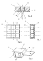
- Fig. 3 From the Fig. 3 is seen in plan view, as several modules 1 (in this case, seven pieces) are received together in holes 16 of the structural housing of the power supply unit 2.
- the structural housing thus forms the current generator unit 2.
- the current receiving unit 6 It is also designed as a structural housing with a plurality of bores for receiving the modules 5.
- the number and shape of the housing structures 2 and 6 depends on the particular application. If you make the structure of the housing 2 and 6 made of plastic, can form a variety of forms. For mass production are, for example, injection molded parts, in which the holes 16 are already introduced in the production in the desired shape.
- the Fig. 4 shows for this purpose a structural housing 2 'or 6' in a rectangular shape, wherein a plurality of modules 1 and 5 are arranged one behind the other.
- a structural housing 2 'and 6' connecting members 17a and 17b which can be interconnected, for example, as snap-action members in the form of male / female parts.
- positive and negative parts 17a and 17b can be arranged at different points of the housing structure (see also dashed representation in the longitudinal walls), which can block-type current generator units 2 'and 6 Stromtechnikerüen connect in any direction or orientation.
- FIGS. 3 and 4 Housing structures shown are as mentioned in the same way both for the current generator unit 2, 2 'and for the Stromstofftechnik 6, 6' possible.
- a module 1 of a current generator unit 2 is shown in a housing structure, which is suitable for low currents or is particularly suitable for the forwarding of signal or control pulses.
- a housing structure which is suitable for low currents or is particularly suitable for the forwarding of signal or control pulses.
- it is not essential to ensure that due to the low amperage to ensure that with a non-patch Strom choirtician knew no contact of the constantly energized magnetic body 1 with the outside of the housing structure or attached to the outside contact plate, but here it is sufficient when the magnetic body 1 is arranged with a small clearance in the housing structure 2 such that it produces a perfect surface contact between the two magnetic bodies 4 and 9 when placing the magnetic body 9 of the Strom choirtician 5.
- an elastic intermediate member 18 is arranged, the corresponding relative movements of the magnetic body 4 relative to the housing housing 2 used in the housing structure 2 permitting.
- an intermediate member 18 may serve, for example, an elastic sealing means, which is introduced into the intermediate space.
- this may be provided with a circumferential collar or with corresponding peripheral projections 19.
- Wegbegrenzungs worn for the magnetic body 4 can according to Fig. 5 serve a threaded nut 20 which is screwed onto a threaded portion of the extension member 13 of the magnetic body 4. It is only necessary to ensure that a game, according to the intended movement of the magnetic body 4 for contacting the magnetic body 9 of the Stromauerbericht 5 to a rear wall 21 of the housing structure 2 is present.
- FIGS. 6 and 7 the embodiment of a housing structure 2 for correspondingly square-shaped magnetic body 4 together with square receiving housings 3 is shown.
- the housing structure 2 is square with, for example, nine square recesses 22 for accommodating one module 1 each consisting of magnetic body 4 and receiving housing 3 with interposed intermediate member 18.
- the Fig. 8 shows the embodiment of the module 1, which is particularly suitable for mass production.
- the magnetic body 4 is rectangular or square and is partially enclosed by a folding member 23, which may be a sheet metal part, for example, as a receiving housing.
- the folding member 23 has laterally Umbordelept 24 for holding and clamping the magnetic body 4.
- a Umfalzung On the side remote from the Strom demandingtechnik 6 side of the folding member 23 is provided with a Umfalzung as a stop member 25, wherein the Umfalzung with an angled portion at the same time an extension member 13 'for one not illustrated power connection forms.
- the Umfalzung is arranged such that it lies with play under or behind the base plate 21.
- the elastic intermediate member 18 (not shown).
Abstract
Description
Die Erfindung betrifft eine Verbindungsvorrichtung zum Herstellen einer elektrischen Verbindung zwischen einer Stromgebereinheit, die mit Stromanschlußkontakten versehene Magnetkörper als Schaltteil aufweist, und einer Stromnehmereinheit, die mit Stromanschlußkontakten versehene Magnetkörper als Stromaufnahmeteil aufweist, wobei bei einem Aufsetzen der Stromgebereinheit auf die Stromnehmereinheit die Magnetkörper von Stromgebereinheit und Stromnehmereinheit sich gegenüberliegend angeordnet sind und wobei die Magnetkörper der Stromnehmereinheit die Magnetkörper der Stromgebereinheit kontaktieren.The invention relates to a connecting device for establishing an electrical connection between a current transmitter unit having provided with power connection contacts magnetic body as a switching part, and a Stromnehmereinheit having provided with electrical connection contacts magnetic body as a current receiving part, wherein when placing the current generator unit on the Stromnehmereinheit the magnetic body of the current generator unit and Stromnehmerereinheit are arranged opposite one another and wherein the magnetic body of the Stromnehmereinheit contact the magnetic body of the power supply unit.
Eine gattungsgemäße Vorrichtung ist in der
In der
In der
Der vorliegenden Erfindung liegt die Aufgabe zugrunde, die vorstehend beschriebenen elektrischen Verbindungsvorrichtungen derart weiterzuentwickeln, daß sie auf vielfältige Weise je nach den geforderten Anforderungen eingesetzt werden können, wobei insbesondere die Anzahl der einzelnen die Stromverbindung herstellenden Magnetkörper beliebig sein soll.The present invention has for its object to further develop the electrical connecting devices described above such that they can be used in many ways depending on the required requirements, in particular, the number of individual the current connection producing magnetic body should be arbitrary.
Erfindungsgemäß wird diese Aufgabe dadurch gelöst, daß die Stromgebereinheit aus einzelnen Modulen gebildet ist, wobei die Module jeweils mit einem in einem Aufnahmegehäuse angeordneten Magnetkörper versehen sind, wobei die Aufnahmegehäuse der Module der Stromgebereinheit jeweils innenseitig als Führung für den in Richtung auf die Stromnehmereinheit in dem Aufnahmegehäuse bewegbaren Magnetkörper dienen, und wobei an dem Aufnahmegehäuse der Stromgebereinheit jeweils auf der von der Stromnehmereinheit abgewandten Seite ein Rückhalteglied oder eine Wegbegrenzungseinrichtung für den Magnetkörper vorgesehen ist.According to the invention this object is achieved in that the current transmitter unit is formed of individual modules, wherein the modules are each provided with a magnetic body arranged in a receiving housing, wherein the receiving housing of the modules of the current generator unit in each case on the inside as a guide for in the direction of the Stromnehmereinheit in the Serve receiving housing movable magnet body, and wherein on the receiving housing of the current generator unit on the side remote from the Stromnehmereinheit side a retaining member or a Wegbegrenzungseinrichtung is provided for the magnetic body.
Erfindungsgemäß wird nunmehr die Stromgebereinheit aus Modulen gebildet, wobei dies vorzugsweise auch für die Stromnehmereinheit gelten kann. Jeder in einem Aufnahmegehäuse angeordnete Magnetkörper bildet eine Einheit und erzeugt aufgrund der Bewegbarkeit in dem Aufnahmegehäuse der Stromgebereinheit einen eigenen schaltenden Kontakt, wobei die Kontaktenergie durch die Magnetkraft erbracht wird, sobald ein Magnetkörper der Stromnehmereinheit aufgesetzt wird.According to the invention, the current generator unit is now formed from modules, and this may preferably also apply to the current unit. Each arranged in a receiving housing magnetic body forms a unit and generated due to the mobility in the receiving housing of the power transmitter unit has its own switching contact, wherein the contact energy is provided by the magnetic force as soon as a magnetic body of the Stromnehmerereinheit is placed.
Im allgemeinen wird man die Stromgebereinheiten derart ausführen, daß die Magnetkörper im Ruhezustand, d.h. wenn die Stromnehmereinheit nicht aufgesetzt ist, durch ein Rückhalteglied in Form eines Magneten oder eines magnetischen Teiles in einer Position gehalten wird, in der keine Stromverbindung zur Außenseite der Stromgebereinheit besteht, wie dies z.B. bei der gattungsgemäßen Vorrichtung
Um eine einwandfreie Kontaktierung und einen Flächenkontakt der Magnetkörper der Stromgebereinheit und der Stromnehmereinheit zu erreichen, um insbesondere hohe Stromstärken ohne Lichtbögen zu ermöglichen, kann in einer vorteilhaften Ausgestaltung der Erfindung vorgesehen sein, daß die der Stromnehmereinheit zugewandten Seite der Gehäusestruktur der Stromgebereinheit elastisch ausgebildet ist.In order to achieve a perfect contact and a surface contact of the magnetic body of the current transmitter unit and the Stromnehmereinheit to allow in particular high currents without arcing, can be provided in an advantageous embodiment of the invention that the Stromnehmereinheit facing side of the housing structure of the current generator unit is formed elastically.
Alternativ dazu ist es auch möglich, zwischen dem Aufnahmegehäuse und dem Magnetkörper der Stromgebereinheit ein elastisches Zwischenglied anzuordnen, das entsprechend die Verschiebung des Magnetkörpers zuläßt.Alternatively, it is also possible between the receiving housing and the magnetic body of the current generator unit an elastic To arrange intermediate member, which allows the corresponding displacement of the magnetic body.
Wenn man dabei gemäß einer erfindungsgemäßen sehr vorteilhaften Weiterbildung mehrere Module mit ihren im Inneren der Aufnahmegehäuse angeordneten Magnetkörpern gemeinsam in einer Gehäusestruktur aufnimmt, lassen sich die Einheiten beliebig modulartig erweitern. Es ist lediglich erforderlich die Aufnahmegehäuse mit den Magnetkörpern in entsprechend angepaßte Aussparungen oder Bohrungen in die Gehäusestruktur einzusetzen. Auf diese Weise lassen sich die vielfältigsten Variationen je nach Einsetzart und Einsetzzahl der Module in eine Gehäusestruktur herstellen. Die Module lassen sich auf diese Weise beliebig an die örtlichen Gegebenheiten anpassen. Zur elektrischen Verbindung können dann jeweils die vorgefertigten Module entsprechend in die Bohrungen oder Aussparungen der Gehäusestruktur eingesetzt werden.If, according to a very advantageous development according to the invention, several modules are accommodated together with their magnet bodies arranged in the interior of the receiving housing together in a housing structure, the units can be expanded in any desired modular manner. It is only necessary to use the receiving housing with the magnetic bodies in correspondingly adapted recesses or holes in the housing structure. In this way, the most varied variations can be produced depending on the Einsetzart and Einsetzzahl the modules in a housing structure. The modules can be adapted to the local conditions in this way. For electrical connection then each of the prefabricated modules can be used according to the holes or recesses of the housing structure.
In gleicher Weise können die Gehäusestrukturen auch als Grundkörper oder Normteil hergestellt werden, mit einer bestimmten Anzahl Aussparungen oder Bohrungen, in die dann je nach Wunsch entsprechend die Magnetmodule eingesetzt werden.In the same way, the housing structures can also be produced as a basic body or standard part, with a certain number of recesses or holes, into which then, as desired, the magnetic modules are used.
In einer sehr vorteilhaften Weiterbildung können dabei die Gehäusestrukturen zusätzlich noch mit Verbindungsgliedern versehen werden. Auf diese Weise lassen sich die Anwendungsmöglichkeiten und die Anzahl der elektrischen Verbindungen noch weiter beliebig steigern. In vorteilhafter Weise wird man hierfür einfach und schnell zu verbindende Verbindungsglieder vorsehen, wie z.B. Schnappverbindungen. Verwendet man hierfür Normteile mit Schnappgliedern mit jeweils Positiv- und Negativteilen (male/female-Verbindung), so lassen sich die vielfältigsten Kombinationen erzielen. Hierfür läßt sich z.B. ein Verbindungssystem verwenden, wie dies z.B. von Lego®-Bausteinen her bekannt ist.In a very advantageous development, the housing structures can additionally be provided with connecting links. In this way, the application possibilities and the number of electrical connections can be further increased arbitrarily. Advantageously, this will provide simple and fast connecting members to be connected, such as snap connections. If you use this standard parts with snap links with each positive and negative parts (male / female connection), so leave to achieve the most diverse combinations. For this, for example, can use a link system, as is known, for example, building blocks ® Lego ago.
Vorteilhafte Ausgestaltungen und Weiterbildungen ergeben sich aus den Unteransprüchen und aus dem nachfolgend anhand der Zeichnung prinzipmäßig beschriebenen Ausführungsbeispiel.Advantageous embodiments and further developments emerge from the dependent claims and from the exemplary embodiment described in principle below with reference to the drawing.
Es zeigt:
- Fig. 1
- eine prinzipmäßige Darstellung eines Moduls einer Stromgebereinheit und eines Moduls einer Stromnehmereinheit;
- Fig.2
- die beiden Module im kontaktierten Zustand von Stromgebereinheit und Stromnehmereinheit;
- Fig.3
- eine Draufsicht in prinzipieller Darstellung einer Stromgebereinheit mit mehreren Modulen in einer gemeinsamen Gehäusestruktur;
- Fig.4
- eine Draufsicht in prinzipieller Darstellung einer Stromgebereinheit mit mehreren Modulen in einer gemeinsamen Gehäusestruktur in einer anderen Ausgestaltung; und
- Fig. 5
- eine prinzipielle Darstellung eines Modules einer Stromgebereinheit in einer anderen Ausgestaltung;
- Fig.6
- eine Gehäusestruktur für ein Modul nach der
Fig. 5 ; - Fig.7
- einen Schnitt nach der Linie VII-VII der
Fig. 6 ; und - Fig. 8
- einen Magnetkörper mit einem Aufnahmegehäuse in Form eines Falzgliedes.
- Fig. 1
- a schematic representation of a module of a current transmitter unit and a module of a Stromnehmereinheit;
- Fig.2
- the two modules in the contacted state of current transmitter unit and Stromnehmerereinheit;
- Figure 3
- a plan view in a schematic representation of a current transmitter unit with a plurality of modules in a common housing structure;
- Figure 4
- a plan view in a schematic representation of a current transmitter unit with a plurality of modules in a common housing structure in another embodiment; and
- Fig. 5
- a schematic representation of a module of a current transmitter unit in another embodiment;
- Figure 6
- a housing structure for a module according to the
Fig. 5 ; - Figure 7
- a section along the line VII-VII of
Fig. 6 ; and - Fig. 8
- a magnetic body with a receiving housing in the form of a folding member.
Da die Funktionsweise und die elektrische Verbindung über die Flachkontakte bildenden Magnetkörper aus den in der Beschreibungseinleitung bereits genannten Schriften hinlänglich bekannt ist, wird nachfolgend nur auf die für die Erfindung wesentlichen Teile eingegangen.Since the operation and the electrical connection via the flat contacts forming magnetic body from the writings already mentioned in the introduction is well known, will be discussed below only on the essential parts of the invention.
Eine Stromgebereinheit mit einer Gehäusestruktur 2, wie sie in der Draufsicht in der
Im Rahmen der vorliegenden Erfindung stellt der Ausdruck "Magnetkörper" die allgemeine Bezeichnung für einen Magneten, einen magnetisierbaren Körper oder ein magnetisches Teil dar, durch welche in Verbindung mit einem zweiten Magnetkörper ein magnetisches Feld erzeugt wird bzw. ein magnetisches Kraftfeld.In the context of the present invention, the term "magnetic body" is the general term for a magnet, a magnetizable body or a magnetic part, through which in conjunction with a second magnetic body, a magnetic field is generated or a magnetic force field.
Der Magnetkörper 4 ist im Inneren des Aufnahmegehäuses 3, welches als Führung für den Magnetkörper 4 ausgebildet ist, axial verschieblich. Vorzugsweise sind der Magnetkörper 4 und das Aufnahmegehäuse 3 zylinderförmig ausgebildet. Selbstverständlich können das Aufnahmegehäuse 3 und der Magnetkörper 4 auch andere Formen, wie z.B. rechteckige oder quadratische Querschnittsformen aufweisen. In jedem Falle muß der Magnetkörper 4 in Richtung auf einem aufzusetzenden Modul 5 einer Stromnehmereinheit 6 verschiebbar bzw. bewegbar sein. Wenn das Aufnahmegehäuse 3 aus nicht elektrisch leitfähigem Kunststoff besteht, muß eine Vorderseite 7, d.h. die Seite die zu der Stromnehmereinheit 6 gerichtet ist, im Bereich des Magnetkörpers 4 mit einer elektrisch leitfähigen Kontaktplatte 8 versehen sein. Gleiches gilt für das Modul 5 der Stromnehmereinheit 6, welche in der
Auf der von der Stromnehmereinheit 6 abgewandten Seite befindet sich im Inneren des Aufnahmegehäuses 3 unter dem Magnetkörper 4 ein Rückhalteglied 12 in Form eines Magneten oder magnetisierbaren Teiles. Im Ruhezustand wird der Magnetkörper 4 von dem Rückhalteglied 12 angezogen und befindet sich damit auf Abstand zu der elektrisch leitfähigen Kontaktplatte 8.On the side facing away from the
Wird nun - wie aus der
Da der Magnetkörper 4 auf seiner Rückseite über ein Verlängerungsglied 13 mit einem elastischen Stromanschlußkontakt 14 versehen ist, wird auf diese Weise auch eine Stromverbindung zu der Stromgebereinheit 1 hergestellt. Bei aufgesetzter Stromnehmereinheit 6 findet aufgrund der elektrischen Kontaktverbindung über die Magnetkörper 4 und 9 mit den Kontaktplatten 8 und 11 eine Stromverbindung zu einem Stromanschlußkontakt 15 auf der Rückseite des Magnetkörpers 9 statt. Der über die Stromgebereinheit 2 eingeleitete Strom oder auch ein Spannungsimpuls kann somit zur Steuerung von elektrischen oder elektronischen Geräten und Einrichtungen eingesetzt werden, die mit dem Stromanschlußkontakt 15 verbunden sind.Since the
Aus der
Gleiches gilt für die Stromnehmereinheit 6. Auch sie ist als Strukturgehäuse mit mehreren Bohrungen zur Aufnahme der Module 5 ausgebildet.The same applies to the
Die Anzahl und die Form der Gehäusestrukturen 2 und 6 richtet sich dabei nach dem jeweiligen Anwendungsfall. Wenn man die Strukturgehäuse 2 und 6 aus Kunststoff herstellt, lassen sich die verschiedensten Formen bilden. Für die Massenherstellung eignen sich z.B. Spritzgußteile, in die die Bohrungen 16 bereits bei der Herstellung in der gewünschten Form eingebracht sind.The number and shape of the
Die
Die in den
Wesentlich ist sowohl für die Stromgebereinheit 2 als auch für die Stromnehmereinheit 6, daß die Module 1 und 5 vorgefertigte Einheiten mit Stromanschlußkontakten 14 und Stronamschlußkontakten 15 bilden, welche dann je nach der gewünschten Anforderung in beliebiger Anzahl und Reihenfolge in die Bohrungen 16 des jeweils dazugehörigen Strukturgehäuses 2 bzw. 6 eingesetzt werden und somit beliebig viele Stromverbindungen herstellen.It is essential both for the
Wenn die Stromzuführung zu den Stromanschlußkontakten 14 der Module 1 individuell bzw. einzeln erfolgt, so lassen sich bei einer entsprechenden Stromzugabe die Module 1 der Stromgebereinheit 2 einzeln aktivieren und somit auch jeweils einzeln bzw. individuell ein Schaltkontakt zu dem dazugehörigen Modul 5 der Stromnehmereinheit 6 herstellen.If the power supply to the
In der
In den
Die
Claims (16)
- Connection device for producing an electrical connection between an electrical current supply unit, which has magnetic bodies which are provided with electrical current connection contacts as a switching member, and an electrical current consumption unit which has magnetic bodies which are provided with electrical current connection contacts as an electrical current input unit, the magnetic bodies of the electrical current supply unit and the electrical current consumption unit being arranged opposite each other when the electrical current supply unit is placed on the electrical current consumption unit and the magnetic bodies of the electrical current consumption unit contacting the magnetic bodies of the electrical current supply unit,
characterised in that the electrical current supply unit (2) is formed from individual modules (1), the modules (1) each being provided with a magnetic body (4) which is arranged in a receiving housing (3), the receiving housings of the modules (1) of the electrical current supply unit (2) each acting internally as a guide for the magnetic body (4) which can be moved in the direction towards the electrical current consumption unit (6) in the receiving housing (3), and a retaining member (12) or a path limitation device for the magnetic body (4) being provided in each case on the receiving housing (3) of the electrical current supply unit (2) at the side remote from the electrical current consumption unit (6), the receiving housings (3) with their magnetic bodies (4) arranged therein being received in a common housing structure which is constructed as an electrical current supply unit (2). - Connection device according to claim 1,
characterised in that
the retaining member (12) is formed by a magnet or a magnetic component. - Connection device according to claim 2,
characterised in that
the side of the housing structure of the electrical current supply unit (2) facing the electrical current consumption unit (6) is constructed in a resilient manner. - Connection device according to claim 1,
characterised in that
a resilient intermediate member (18) is arranged in each case between the receiving housing (3) and the magnetic body (4) of the electrical current supply unit (2). - Connection device according to claim 1 and claim 4, characterised in that the path limitation device is formed by a stop member (20) which is connected to the magnetic body (4) and which is provided with a clearance and which, when the magnetic body (4) of the electrical current supply unit (2) comes into contact with the positioned magnetic body (9) of the electrical current consumption unit (6), moves into abutment against the receiving housing (3).
- Connection device according to claim 5,
characterised in that
the receiving housing (3) is formed by a folding member which at least partially comprises the magnetic body (4), the folding member being provided with a fold as a stop member (25) at the side remote from the electrical current consumption unit (6). - Connection device according to claim 6,
characterised in that
the folding member at the same time also forms the extension member (13') for a current connection contact (14). - Connection device according to claim 1,
characterised in that
the electrical current consumption unit (6) is formed from individual modules (5) which each have a magnetic body (9) which is arranged in a receiving housing (10). - Connection device according to claim 8,
characterised in that
a plurality of receiving housings (10) with the magnetic bodies (9) arranged in the interior are received in a common structural housing which is constructed as an electrical current consumption unit (6). - Connection device according to any one of claims 1 to 9,
characterised in that
the receiving housings (2, 6) comprise a non-electrically conductive material, preferably plastics material, electrically conductive contact plates (8, 11) being arranged at the side of the receiving housing (3 or 10) directed towards the other unit. - Connection device according to any one of claims 1 to 10,
characterised in that
the receiving housings (3, 10) are received in recesses or holes (16) of the associated housing structure. - Connection device according to any one of claims 1 to 11,
characterised in that
the housing structures can be connected to each other in a modular manner by means of connection members (17a, 17b) which are arranged on the housing structures. - Connection device according to claim 12,
characterised in that
the connection members (17a, 17b) are constructed as resiliently formed snap-fit connections with a positive component and a negative component in the form of a male/female connection. - Connection device according to claim 1,
characterised in that
the modules (1) of the electrical current supply unit (2) can be switched individually and independently of each other by means of selective electrical current supplies to the electrical current connection contacts (14) of the magnetic bodies (4). - Connection device according to claim 1,
characterised in that
the modules (1) can be switched together by supplying electrical current to the electrical current connection contacts (14) of the magnetic bodies (4). - Connection device according to claim 1,
characterised in that
the magnetic bodies (4, 9) comprise encoded magnets, magnetic bodies (4, 9) with different polarisation being arranged opposite each other in the electrical current supply unit (2) and the electrical current consumption unit (6).
Applications Claiming Priority (3)
| Application Number | Priority Date | Filing Date | Title |
|---|---|---|---|
| DE10225968A DE10225968A1 (en) | 2002-06-11 | 2002-06-11 | Connection device for establishing an electrical connection |
| DE10225968 | 2002-06-11 | ||
| PCT/EP2003/005942 WO2003105286A1 (en) | 2002-06-11 | 2003-06-06 | Connection device for the production of an electric connection |
Publications (2)
| Publication Number | Publication Date |
|---|---|
| EP1516398A1 EP1516398A1 (en) | 2005-03-23 |
| EP1516398B1 true EP1516398B1 (en) | 2010-04-21 |
Family
ID=29594394
Family Applications (1)
| Application Number | Title | Priority Date | Filing Date |
|---|---|---|---|
| EP03740196A Expired - Lifetime EP1516398B1 (en) | 2002-06-11 | 2003-06-06 | Connection device for the production of an electric connection |
Country Status (5)
| Country | Link |
|---|---|
| EP (1) | EP1516398B1 (en) |
| AT (1) | ATE465531T1 (en) |
| AU (1) | AU2003273662A1 (en) |
| DE (2) | DE10225968A1 (en) |
| WO (1) | WO2003105286A1 (en) |
Family Cites Families (1)
| Publication number | Priority date | Publication date | Assignee | Title |
|---|---|---|---|---|
| DE29516069U1 (en) * | 1995-10-06 | 1995-12-14 | Fritsch Klaus Dieter | Receiving device for an electric light source |
-
2002
- 2002-06-11 DE DE10225968A patent/DE10225968A1/en not_active Withdrawn
-
2003
- 2003-06-06 EP EP03740196A patent/EP1516398B1/en not_active Expired - Lifetime
- 2003-06-06 DE DE50312644T patent/DE50312644D1/en not_active Expired - Lifetime
- 2003-06-06 AT AT03740196T patent/ATE465531T1/en not_active IP Right Cessation
- 2003-06-06 WO PCT/EP2003/005942 patent/WO2003105286A1/en not_active Application Discontinuation
- 2003-06-06 AU AU2003273662A patent/AU2003273662A1/en not_active Abandoned
Also Published As
| Publication number | Publication date |
|---|---|
| ATE465531T1 (en) | 2010-05-15 |
| DE10225968A1 (en) | 2003-12-24 |
| DE50312644D1 (en) | 2010-06-02 |
| EP1516398A1 (en) | 2005-03-23 |
| WO2003105286A1 (en) | 2003-12-18 |
| AU2003273662A1 (en) | 2003-12-22 |
Similar Documents
| Publication | Publication Date | Title |
|---|---|---|
| EP1194983B1 (en) | Electromechanical connecting device | |
| DE10242646A1 (en) | Electrical connection device between current or data source device and current or data reception device, uses elastically mounted contact elements acted on by pressure bridge | |
| EP0819326B1 (en) | Electromechanical connection device | |
| DE20317436U1 (en) | Electrical connection device | |
| DE10242645A1 (en) | Method of creating electrical connection to modules e.g. in motor vehicle, by using magnetic bodies in current providing unit and current receiving unit to form contact automatically | |
| EP2338210B1 (en) | Electromechanical connection system | |
| EP2638580A1 (en) | Electrochemical energy store comprising an attachment element | |
| EP2135337B1 (en) | Low-voltage, medium-voltage or high-voltage switching or control device, in particular a switchgear assembly | |
| DE19627481C2 (en) | Electrical switch and fuse device | |
| EP0982978A2 (en) | Housing, in particular lock housing with electrical interconnections | |
| EP1516398B1 (en) | Connection device for the production of an electric connection | |
| DE2920288A1 (en) | PROTECTIVE PLUG FOR CONNECTING BLOCKS | |
| EP1297547B1 (en) | Connecting bars for electrical devices and apparatus for different nominal currents having a cavity | |
| EP1869688B1 (en) | Multi-pole switching device with an additional housing and a mutual mechanical locking apparatus | |
| EP2897230A1 (en) | Electrical connection in particular for an electrical heating system of a vehicle | |
| EP0669198A1 (en) | Injection moulding apparatus | |
| DE3432025A1 (en) | Switching apparatus, especially for switching high-power current loads on and off | |
| EP0481335A2 (en) | Switch device | |
| DE2304629C3 (en) | Terminal block, in particular switchgear terminal block | |
| DE2462035C3 (en) | keyboard | |
| DE102018206054B4 (en) | Contactor | |
| DE19539958A1 (en) | Contact for conducting electric current in conductor lead e.g. for contact rails | |
| DE1959943A1 (en) | Kit for building electrical circuits | |
| DE2061376A1 (en) | Electric switch, in particular for battery-operated toys | |
| DE3131003A1 (en) | Electrical switch, especially for motor vehicles |
Legal Events
| Date | Code | Title | Description |
|---|---|---|---|
| PUAI | Public reference made under article 153(3) epc to a published international application that has entered the european phase |
Free format text: ORIGINAL CODE: 0009012 |
|
| 17P | Request for examination filed |
Effective date: 20041229 |
|
| AK | Designated contracting states |
Kind code of ref document: A1 Designated state(s): AT BE BG CH CY CZ DE DK EE ES FI FR GB GR HU IE IT LI LU MC NL PT RO SE SI SK TR |
|
| AX | Request for extension of the european patent |
Extension state: AL LT LV MK |
|
| DAX | Request for extension of the european patent (deleted) | ||
| GRAP | Despatch of communication of intention to grant a patent |
Free format text: ORIGINAL CODE: EPIDOSNIGR1 |
|
| GRAS | Grant fee paid |
Free format text: ORIGINAL CODE: EPIDOSNIGR3 |
|
| GRAA | (expected) grant |
Free format text: ORIGINAL CODE: 0009210 |
|
| RAP1 | Party data changed (applicant data changed or rights of an application transferred) |
Owner name: ROSENBERGER HOCHFREQUENZTECHNIK GMBH & CO. KG |
|
| AK | Designated contracting states |
Kind code of ref document: B1 Designated state(s): AT BE BG CH CY CZ DE DK EE ES FI FR GB GR HU IE IT LI LU MC NL PT RO SE SI SK TR |
|
| REG | Reference to a national code |
Ref country code: GB Ref legal event code: FG4D Free format text: NOT ENGLISH |
|
| REG | Reference to a national code |
Ref country code: CH Ref legal event code: NV Representative=s name: CABINET ROLAND NITHARDT CONSEILS EN PROPRIETE INDU Ref country code: CH Ref legal event code: EP |
|
| REG | Reference to a national code |
Ref country code: IE Ref legal event code: FG4D Free format text: LANGUAGE OF EP DOCUMENT: GERMAN |
|
| REF | Corresponds to: |
Ref document number: 50312644 Country of ref document: DE Date of ref document: 20100602 Kind code of ref document: P |
|
| REG | Reference to a national code |
Ref country code: SE Ref legal event code: TRGR |
|
| REG | Reference to a national code |
Ref country code: NL Ref legal event code: VDEP Effective date: 20100421 |
|
| PG25 | Lapsed in a contracting state [announced via postgrant information from national office to epo] |
Ref country code: NL Free format text: LAPSE BECAUSE OF FAILURE TO SUBMIT A TRANSLATION OF THE DESCRIPTION OR TO PAY THE FEE WITHIN THE PRESCRIBED TIME-LIMIT Effective date: 20100421 Ref country code: ES Free format text: LAPSE BECAUSE OF FAILURE TO SUBMIT A TRANSLATION OF THE DESCRIPTION OR TO PAY THE FEE WITHIN THE PRESCRIBED TIME-LIMIT Effective date: 20100801 |
|
| REG | Reference to a national code |
Ref country code: IE Ref legal event code: FD4D |
|
| PG25 | Lapsed in a contracting state [announced via postgrant information from national office to epo] |
Ref country code: SI Free format text: LAPSE BECAUSE OF FAILURE TO SUBMIT A TRANSLATION OF THE DESCRIPTION OR TO PAY THE FEE WITHIN THE PRESCRIBED TIME-LIMIT Effective date: 20100421 |
|
| BERE | Be: lapsed |
Owner name: ROSENBERGER HOCHFREQUENZTECHNIK G.M.B.H. & CO. KG Effective date: 20100630 |
|
| PG25 | Lapsed in a contracting state [announced via postgrant information from national office to epo] |
Ref country code: GR Free format text: LAPSE BECAUSE OF FAILURE TO SUBMIT A TRANSLATION OF THE DESCRIPTION OR TO PAY THE FEE WITHIN THE PRESCRIBED TIME-LIMIT Effective date: 20100722 Ref country code: CY Free format text: LAPSE BECAUSE OF FAILURE TO SUBMIT A TRANSLATION OF THE DESCRIPTION OR TO PAY THE FEE WITHIN THE PRESCRIBED TIME-LIMIT Effective date: 20100421 |
|
| PG25 | Lapsed in a contracting state [announced via postgrant information from national office to epo] |
Ref country code: IE Free format text: LAPSE BECAUSE OF FAILURE TO SUBMIT A TRANSLATION OF THE DESCRIPTION OR TO PAY THE FEE WITHIN THE PRESCRIBED TIME-LIMIT Effective date: 20100421 Ref country code: PT Free format text: LAPSE BECAUSE OF FAILURE TO SUBMIT A TRANSLATION OF THE DESCRIPTION OR TO PAY THE FEE WITHIN THE PRESCRIBED TIME-LIMIT Effective date: 20100823 Ref country code: EE Free format text: LAPSE BECAUSE OF FAILURE TO SUBMIT A TRANSLATION OF THE DESCRIPTION OR TO PAY THE FEE WITHIN THE PRESCRIBED TIME-LIMIT Effective date: 20100421 Ref country code: DK Free format text: LAPSE BECAUSE OF FAILURE TO SUBMIT A TRANSLATION OF THE DESCRIPTION OR TO PAY THE FEE WITHIN THE PRESCRIBED TIME-LIMIT Effective date: 20100421 Ref country code: MC Free format text: LAPSE BECAUSE OF NON-PAYMENT OF DUE FEES Effective date: 20100630 |
|
| PLBE | No opposition filed within time limit |
Free format text: ORIGINAL CODE: 0009261 |
|
| STAA | Information on the status of an ep patent application or granted ep patent |
Free format text: STATUS: NO OPPOSITION FILED WITHIN TIME LIMIT |
|
| PG25 | Lapsed in a contracting state [announced via postgrant information from national office to epo] |
Ref country code: RO Free format text: LAPSE BECAUSE OF FAILURE TO SUBMIT A TRANSLATION OF THE DESCRIPTION OR TO PAY THE FEE WITHIN THE PRESCRIBED TIME-LIMIT Effective date: 20100421 Ref country code: CZ Free format text: LAPSE BECAUSE OF FAILURE TO SUBMIT A TRANSLATION OF THE DESCRIPTION OR TO PAY THE FEE WITHIN THE PRESCRIBED TIME-LIMIT Effective date: 20100421 Ref country code: SK Free format text: LAPSE BECAUSE OF FAILURE TO SUBMIT A TRANSLATION OF THE DESCRIPTION OR TO PAY THE FEE WITHIN THE PRESCRIBED TIME-LIMIT Effective date: 20100421 |
|
| 26N | No opposition filed |
Effective date: 20110124 |
|
| PG25 | Lapsed in a contracting state [announced via postgrant information from national office to epo] |
Ref country code: BE Free format text: LAPSE BECAUSE OF NON-PAYMENT OF DUE FEES Effective date: 20100630 |
|
| PG25 | Lapsed in a contracting state [announced via postgrant information from national office to epo] |
Ref country code: AT Free format text: LAPSE BECAUSE OF NON-PAYMENT OF DUE FEES Effective date: 20100606 |
|
| PG25 | Lapsed in a contracting state [announced via postgrant information from national office to epo] |
Ref country code: LU Free format text: LAPSE BECAUSE OF NON-PAYMENT OF DUE FEES Effective date: 20100606 Ref country code: BG Free format text: LAPSE BECAUSE OF FAILURE TO SUBMIT A TRANSLATION OF THE DESCRIPTION OR TO PAY THE FEE WITHIN THE PRESCRIBED TIME-LIMIT Effective date: 20100421 Ref country code: HU Free format text: LAPSE BECAUSE OF FAILURE TO SUBMIT A TRANSLATION OF THE DESCRIPTION OR TO PAY THE FEE WITHIN THE PRESCRIBED TIME-LIMIT Effective date: 20101022 |
|
| PG25 | Lapsed in a contracting state [announced via postgrant information from national office to epo] |
Ref country code: TR Free format text: LAPSE BECAUSE OF FAILURE TO SUBMIT A TRANSLATION OF THE DESCRIPTION OR TO PAY THE FEE WITHIN THE PRESCRIBED TIME-LIMIT Effective date: 20100421 |
|
| PG25 | Lapsed in a contracting state [announced via postgrant information from national office to epo] |
Ref country code: BG Free format text: LAPSE BECAUSE OF FAILURE TO SUBMIT A TRANSLATION OF THE DESCRIPTION OR TO PAY THE FEE WITHIN THE PRESCRIBED TIME-LIMIT Effective date: 20100721 |
|
| REG | Reference to a national code |
Ref country code: FR Ref legal event code: PLFP Year of fee payment: 14 |
|
| REG | Reference to a national code |
Ref country code: FR Ref legal event code: PLFP Year of fee payment: 15 |
|
| REG | Reference to a national code |
Ref country code: FR Ref legal event code: PLFP Year of fee payment: 16 |
|
| REG | Reference to a national code |
Ref country code: CH Ref legal event code: NV Representative=s name: ACTOSPHERE SARL, CH |
|
| PGFP | Annual fee paid to national office [announced via postgrant information from national office to epo] |
Ref country code: SE Payment date: 20220622 Year of fee payment: 20 Ref country code: IT Payment date: 20220622 Year of fee payment: 20 Ref country code: GB Payment date: 20220621 Year of fee payment: 20 |
|
| PGFP | Annual fee paid to national office [announced via postgrant information from national office to epo] |
Ref country code: FI Payment date: 20220621 Year of fee payment: 20 |
|
| PGFP | Annual fee paid to national office [announced via postgrant information from national office to epo] |
Ref country code: FR Payment date: 20220623 Year of fee payment: 20 |
|
| PGFP | Annual fee paid to national office [announced via postgrant information from national office to epo] |
Ref country code: DE Payment date: 20220628 Year of fee payment: 20 |
|
| PGFP | Annual fee paid to national office [announced via postgrant information from national office to epo] |
Ref country code: CH Payment date: 20220628 Year of fee payment: 20 |
|
| REG | Reference to a national code |
Ref country code: DE Ref legal event code: R071 Ref document number: 50312644 Country of ref document: DE |
|
| REG | Reference to a national code |
Ref country code: CH Ref legal event code: PL |
|
| P01 | Opt-out of the competence of the unified patent court (upc) registered |
Effective date: 20230515 |
|
| REG | Reference to a national code |
Ref country code: GB Ref legal event code: PE20 Expiry date: 20230605 |
|
| REG | Reference to a national code |
Ref country code: SE Ref legal event code: EUG |
|
| PG25 | Lapsed in a contracting state [announced via postgrant information from national office to epo] |
Ref country code: GB Free format text: LAPSE BECAUSE OF EXPIRATION OF PROTECTION Effective date: 20230605 |