EP1540323B1 - Procédé de fabrication d'un circuit pout bio-capteur comprenant une électrode de référence intégrée - Google Patents
Procédé de fabrication d'un circuit pout bio-capteur comprenant une électrode de référence intégrée Download PDFInfo
- Publication number
- EP1540323B1 EP1540323B1 EP03769206A EP03769206A EP1540323B1 EP 1540323 B1 EP1540323 B1 EP 1540323B1 EP 03769206 A EP03769206 A EP 03769206A EP 03769206 A EP03769206 A EP 03769206A EP 1540323 B1 EP1540323 B1 EP 1540323B1
- Authority
- EP
- European Patent Office
- Prior art keywords
- silver
- reference electrode
- core
- substrate
- electrode
- Prior art date
- Legal status (The legal status is an assumption and is not a legal conclusion. Google has not performed a legal analysis and makes no representation as to the accuracy of the status listed.)
- Expired - Lifetime
Links
- 238000004519 manufacturing process Methods 0.000 title claims description 12
- BQCADISMDOOEFD-UHFFFAOYSA-N Silver Chemical compound [Ag] BQCADISMDOOEFD-UHFFFAOYSA-N 0.000 claims description 88
- 239000004332 silver Substances 0.000 claims description 61
- 229910052709 silver Inorganic materials 0.000 claims description 60
- 239000000758 substrate Substances 0.000 claims description 45
- 238000000034 method Methods 0.000 claims description 42
- HKZLPVFGJNLROG-UHFFFAOYSA-M silver monochloride Chemical compound [Cl-].[Ag+] HKZLPVFGJNLROG-UHFFFAOYSA-M 0.000 claims description 32
- 229910021607 Silver chloride Inorganic materials 0.000 claims description 31
- 239000000463 material Substances 0.000 claims description 28
- 238000007639 printing Methods 0.000 claims description 27
- 230000008878 coupling Effects 0.000 claims description 22
- 238000010168 coupling process Methods 0.000 claims description 22
- 238000005859 coupling reaction Methods 0.000 claims description 22
- GGCZERPQGJTIQP-UHFFFAOYSA-N sodium;9,10-dioxoanthracene-2-sulfonic acid Chemical compound [Na+].C1=CC=C2C(=O)C3=CC(S(=O)(=O)O)=CC=C3C(=O)C2=C1 GGCZERPQGJTIQP-UHFFFAOYSA-N 0.000 claims description 15
- 239000000126 substance Substances 0.000 claims description 13
- 229910052751 metal Inorganic materials 0.000 claims description 12
- 239000002184 metal Substances 0.000 claims description 12
- 150000003839 salts Chemical class 0.000 claims description 11
- PCHJSUWPFVWCPO-UHFFFAOYSA-N gold Chemical compound [Au] PCHJSUWPFVWCPO-UHFFFAOYSA-N 0.000 claims description 10
- 229910052737 gold Inorganic materials 0.000 claims description 10
- 239000010931 gold Substances 0.000 claims description 10
- BASFCYQUMIYNBI-UHFFFAOYSA-N platinum Chemical compound [Pt] BASFCYQUMIYNBI-UHFFFAOYSA-N 0.000 claims description 7
- 239000004065 semiconductor Substances 0.000 claims description 5
- 238000002848 electrochemical method Methods 0.000 claims description 4
- 239000000919 ceramic Substances 0.000 claims description 3
- 239000011521 glass Substances 0.000 claims description 3
- 239000004033 plastic Substances 0.000 claims description 3
- 229910052697 platinum Inorganic materials 0.000 claims description 3
- 238000003491 array Methods 0.000 claims 6
- 239000000243 solution Substances 0.000 description 29
- 108020004414 DNA Proteins 0.000 description 17
- 239000012491 analyte Substances 0.000 description 14
- 238000005516 engineering process Methods 0.000 description 14
- XUIMIQQOPSSXEZ-UHFFFAOYSA-N Silicon Chemical compound [Si] XUIMIQQOPSSXEZ-UHFFFAOYSA-N 0.000 description 11
- 239000003792 electrolyte Substances 0.000 description 11
- 230000008569 process Effects 0.000 description 11
- 229910052710 silicon Inorganic materials 0.000 description 11
- 239000010703 silicon Substances 0.000 description 11
- 238000005660 chlorination reaction Methods 0.000 description 10
- FAPWRFPIFSIZLT-UHFFFAOYSA-M Sodium chloride Chemical compound [Na+].[Cl-] FAPWRFPIFSIZLT-UHFFFAOYSA-M 0.000 description 9
- 239000012266 salt solution Substances 0.000 description 8
- 108020003215 DNA Probes Proteins 0.000 description 7
- 239000003298 DNA probe Substances 0.000 description 7
- 238000005253 cladding Methods 0.000 description 7
- 229910052721 tungsten Inorganic materials 0.000 description 7
- 239000010937 tungsten Substances 0.000 description 7
- KWYUFKZDYYNOTN-UHFFFAOYSA-M Potassium hydroxide Chemical compound [OH-].[K+] KWYUFKZDYYNOTN-UHFFFAOYSA-M 0.000 description 6
- HEMHJVSKTPXQMS-UHFFFAOYSA-M Sodium hydroxide Chemical compound [OH-].[Na+] HEMHJVSKTPXQMS-UHFFFAOYSA-M 0.000 description 6
- 239000003638 chemical reducing agent Substances 0.000 description 6
- WFKWXMTUELFFGS-UHFFFAOYSA-N tungsten Chemical compound [W] WFKWXMTUELFFGS-UHFFFAOYSA-N 0.000 description 6
- VEXZGXHMUGYJMC-UHFFFAOYSA-M Chloride anion Chemical compound [Cl-] VEXZGXHMUGYJMC-UHFFFAOYSA-M 0.000 description 5
- 102000004190 Enzymes Human genes 0.000 description 5
- 108090000790 Enzymes Proteins 0.000 description 5
- WCUXLLCKKVVCTQ-UHFFFAOYSA-M Potassium chloride Chemical compound [Cl-].[K+] WCUXLLCKKVVCTQ-UHFFFAOYSA-M 0.000 description 5
- 239000007864 aqueous solution Substances 0.000 description 5
- RBTARNINKXHZNM-UHFFFAOYSA-K iron trichloride Chemical compound Cl[Fe](Cl)Cl RBTARNINKXHZNM-UHFFFAOYSA-K 0.000 description 5
- 238000002493 microarray Methods 0.000 description 5
- 229910021578 Iron(III) chloride Inorganic materials 0.000 description 4
- 230000008901 benefit Effects 0.000 description 4
- 239000000460 chlorine Substances 0.000 description 4
- XEEYBQQBJWHFJM-UHFFFAOYSA-N iron Substances [Fe] XEEYBQQBJWHFJM-UHFFFAOYSA-N 0.000 description 4
- 238000004064 recycling Methods 0.000 description 4
- 239000003124 biologic agent Substances 0.000 description 3
- 238000001311 chemical methods and process Methods 0.000 description 3
- 238000006243 chemical reaction Methods 0.000 description 3
- 238000004140 cleaning Methods 0.000 description 3
- 238000000840 electrochemical analysis Methods 0.000 description 3
- 238000009713 electroplating Methods 0.000 description 3
- 239000000203 mixture Substances 0.000 description 3
- 238000006722 reduction reaction Methods 0.000 description 3
- 239000000523 sample Substances 0.000 description 3
- HAAYBYDROVFKPU-UHFFFAOYSA-N silver;azane;nitrate Chemical compound N.N.[Ag+].[O-][N+]([O-])=O HAAYBYDROVFKPU-UHFFFAOYSA-N 0.000 description 3
- 239000011734 sodium Substances 0.000 description 3
- 239000011780 sodium chloride Substances 0.000 description 3
- 101710134784 Agnoprotein Proteins 0.000 description 2
- 238000000018 DNA microarray Methods 0.000 description 2
- WQZGKKKJIJFFOK-GASJEMHNSA-N Glucose Natural products OC[C@H]1OC(O)[C@H](O)[C@@H](O)[C@@H]1O WQZGKKKJIJFFOK-GASJEMHNSA-N 0.000 description 2
- OAKJQQAXSVQMHS-UHFFFAOYSA-N Hydrazine Chemical compound NN OAKJQQAXSVQMHS-UHFFFAOYSA-N 0.000 description 2
- UFHFLCQGNIYNRP-UHFFFAOYSA-N Hydrogen Chemical compound [H][H] UFHFLCQGNIYNRP-UHFFFAOYSA-N 0.000 description 2
- 230000002378 acidificating effect Effects 0.000 description 2
- 150000001450 anions Chemical class 0.000 description 2
- 230000000295 complement effect Effects 0.000 description 2
- 239000007822 coupling agent Substances 0.000 description 2
- 230000008021 deposition Effects 0.000 description 2
- 238000001514 detection method Methods 0.000 description 2
- 238000005530 etching Methods 0.000 description 2
- 239000007789 gas Substances 0.000 description 2
- 239000008103 glucose Substances 0.000 description 2
- 239000001257 hydrogen Substances 0.000 description 2
- 229910052739 hydrogen Inorganic materials 0.000 description 2
- 150000002500 ions Chemical class 0.000 description 2
- 229910000510 noble metal Inorganic materials 0.000 description 2
- 239000003960 organic solvent Substances 0.000 description 2
- 230000003647 oxidation Effects 0.000 description 2
- 238000007254 oxidation reaction Methods 0.000 description 2
- 239000002245 particle Substances 0.000 description 2
- 239000001103 potassium chloride Substances 0.000 description 2
- 235000011164 potassium chloride Nutrition 0.000 description 2
- 230000009467 reduction Effects 0.000 description 2
- -1 silver ions Chemical class 0.000 description 2
- JKFYKCYQEWQPTM-UHFFFAOYSA-N 2-azaniumyl-2-(4-fluorophenyl)acetate Chemical compound OC(=O)C(N)C1=CC=C(F)C=C1 JKFYKCYQEWQPTM-UHFFFAOYSA-N 0.000 description 1
- OKTJSMMVPCPJKN-UHFFFAOYSA-N Carbon Chemical compound [C] OKTJSMMVPCPJKN-UHFFFAOYSA-N 0.000 description 1
- ZAMOUSCENKQFHK-UHFFFAOYSA-N Chlorine atom Chemical compound [Cl] ZAMOUSCENKQFHK-UHFFFAOYSA-N 0.000 description 1
- 102000053602 DNA Human genes 0.000 description 1
- DGAQECJNVWCQMB-PUAWFVPOSA-M Ilexoside XXIX Chemical compound C[C@@H]1CC[C@@]2(CC[C@@]3(C(=CC[C@H]4[C@]3(CC[C@@H]5[C@@]4(CC[C@@H](C5(C)C)OS(=O)(=O)[O-])C)C)[C@@H]2[C@]1(C)O)C)C(=O)O[C@H]6[C@@H]([C@H]([C@@H]([C@H](O6)CO)O)O)O.[Na+] DGAQECJNVWCQMB-PUAWFVPOSA-M 0.000 description 1
- 239000000020 Nitrocellulose Substances 0.000 description 1
- ZLMJMSJWJFRBEC-UHFFFAOYSA-N Potassium Chemical compound [K] ZLMJMSJWJFRBEC-UHFFFAOYSA-N 0.000 description 1
- 229910021612 Silver iodide Inorganic materials 0.000 description 1
- 230000003213 activating effect Effects 0.000 description 1
- 239000013543 active substance Substances 0.000 description 1
- 230000003321 amplification Effects 0.000 description 1
- 238000004458 analytical method Methods 0.000 description 1
- 238000013459 approach Methods 0.000 description 1
- QZPSXPBJTPJTSZ-UHFFFAOYSA-N aqua regia Chemical compound Cl.O[N+]([O-])=O QZPSXPBJTPJTSZ-UHFFFAOYSA-N 0.000 description 1
- 238000012742 biochemical analysis Methods 0.000 description 1
- 229940075397 calomel Drugs 0.000 description 1
- 229910052799 carbon Inorganic materials 0.000 description 1
- 239000002800 charge carrier Substances 0.000 description 1
- 229910052801 chlorine Inorganic materials 0.000 description 1
- 239000011248 coating agent Substances 0.000 description 1
- 238000000576 coating method Methods 0.000 description 1
- 230000001419 dependent effect Effects 0.000 description 1
- 238000013461 design Methods 0.000 description 1
- 238000011161 development Methods 0.000 description 1
- 230000018109 developmental process Effects 0.000 description 1
- ZOMNIUBKTOKEHS-UHFFFAOYSA-L dimercury dichloride Chemical compound Cl[Hg][Hg]Cl ZOMNIUBKTOKEHS-UHFFFAOYSA-L 0.000 description 1
- 238000001035 drying Methods 0.000 description 1
- 230000000694 effects Effects 0.000 description 1
- 239000012799 electrically-conductive coating Substances 0.000 description 1
- 230000005518 electrochemistry Effects 0.000 description 1
- 239000007772 electrode material Substances 0.000 description 1
- 238000011010 flushing procedure Methods 0.000 description 1
- 238000010438 heat treatment Methods 0.000 description 1
- 238000009396 hybridization Methods 0.000 description 1
- 238000011835 investigation Methods 0.000 description 1
- 239000004922 lacquer Substances 0.000 description 1
- 239000003446 ligand Substances 0.000 description 1
- 239000007788 liquid Substances 0.000 description 1
- 238000001459 lithography Methods 0.000 description 1
- 239000011159 matrix material Substances 0.000 description 1
- 229910021645 metal ion Inorganic materials 0.000 description 1
- 239000007769 metal material Substances 0.000 description 1
- 229920001220 nitrocellulos Polymers 0.000 description 1
- 238000003199 nucleic acid amplification method Methods 0.000 description 1
- 229910052700 potassium Inorganic materials 0.000 description 1
- 239000011591 potassium Substances 0.000 description 1
- 239000002244 precipitate Substances 0.000 description 1
- 239000000376 reactant Substances 0.000 description 1
- 230000009257 reactivity Effects 0.000 description 1
- 239000012487 rinsing solution Substances 0.000 description 1
- 238000007650 screen-printing Methods 0.000 description 1
- 229940045105 silver iodide Drugs 0.000 description 1
- 229910052708 sodium Inorganic materials 0.000 description 1
- 239000007790 solid phase Substances 0.000 description 1
Images

Classifications
-
- G—PHYSICS
- G01—MEASURING; TESTING
- G01N—INVESTIGATING OR ANALYSING MATERIALS BY DETERMINING THEIR CHEMICAL OR PHYSICAL PROPERTIES
- G01N33/00—Investigating or analysing materials by specific methods not covered by groups G01N1/00 - G01N31/00
- G01N33/48—Biological material, e.g. blood, urine; Haemocytometers
- G01N33/50—Chemical analysis of biological material, e.g. blood, urine; Testing involving biospecific ligand binding methods; Immunological testing
- G01N33/53—Immunoassay; Biospecific binding assay; Materials therefor
- G01N33/543—Immunoassay; Biospecific binding assay; Materials therefor with an insoluble carrier for immobilising immunochemicals
- G01N33/54366—Apparatus specially adapted for solid-phase testing
- G01N33/54373—Apparatus specially adapted for solid-phase testing involving physiochemical end-point determination, e.g. wave-guides, FETS, gratings
- G01N33/5438—Electrodes
-
- G—PHYSICS
- G01—MEASURING; TESTING
- G01N—INVESTIGATING OR ANALYSING MATERIALS BY DETERMINING THEIR CHEMICAL OR PHYSICAL PROPERTIES
- G01N27/00—Investigating or analysing materials by the use of electric, electrochemical, or magnetic means
- G01N27/26—Investigating or analysing materials by the use of electric, electrochemical, or magnetic means by investigating electrochemical variables; by using electrolysis or electrophoresis
- G01N27/28—Electrolytic cell components
- G01N27/30—Electrodes, e.g. test electrodes; Half-cells
- G01N27/327—Biochemical electrodes, e.g. electrical or mechanical details for in vitro measurements
- G01N27/3275—Sensing specific biomolecules, e.g. nucleic acid strands, based on an electrode surface reaction
- G01N27/3277—Sensing specific biomolecules, e.g. nucleic acid strands, based on an electrode surface reaction being a redox reaction, e.g. detection by cyclic voltammetry
Definitions
- the invention relates to a method for producing a biosensor circuit arrangement.
- electrochemical methods are often used to obtain qualitative or quantitative information about a concentration of a redox-active substance in an analyte.
- the reduction or oxidation potentials of the substances to be investigated and electrical current values occurring at electrodes are frequently determined and evaluated.
- E is the electrical potential of a redox system
- E 0 is a standard electrical potential
- R is the gas constant
- T is the absolute temperature
- n is the electrochemical valence
- F is the Faraday constant
- [Ox] is the concentration of the oxidized form
- [Red ] the concentration of the reduced form of the redox substance.
- Such a reference potential is provided by means of a reference electrode.
- a reference electrode of the first kind the electrical potential is determined by the electrochemical equilibrium between the material of the electrode and its ions in the solution.
- the metal ions in the solution have a decisive influence on the electrical potential.
- An example of a reference electrode of the first type is the hydrogen electrode.
- an electrically conductive structure allows the charge exchange between two media.
- a reference electrode of the second kind there is known an arrangement in which the concentration of ions determining electric potential is determined by the presence of a sparingly soluble equi-ionic compound which provides a second solid phase.
- a reference electrode of the second kind is a metal which is covered with a layer of a sparingly soluble salt of the metal and immersed in the solution of an easily soluble salt having a common anion with the sparingly soluble salt.
- the electrode potential is determined by the activity of the anions of the easily soluble salt.
- Examples of reference electrodes of the second kind are the calomel electrode or the silver / silver chloride electrode.
- One embodiment of a silver / silver chloride electrode has a silver chloride-coated silver wire immersed in a chloride ion-containing solution.
- the concentration of silver ions is very small and due to the balance due to the presence of the chloride ions in the solution Ag + + Cl - ⁇ AgCl (2) established.
- electrochemical analysis methods use macroscopic reference electrodes, in particular a silver / silver chloride electrode, which are brought into operative contact with the analyte.
- Typical dimensions of such electrodes range from several centimeters to a few millimeters.
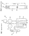
- a prior art electrochemical experimental assembly 100 is shown.
- a container 101 an analyte 102 is filled, which is examined by means of working electrodes 103, 104 electrochemically.
- the first working electrode 103 is coupled to a power supply 105, whereas the second working electrode 104 is coupled to an ammeter 106.
- a voltmeter 107 is connected between the first working electrode 103 and a silver wire-coated silver wire 110 of a silver / silver chloride electrode assembly 109.
- the analyte 102 is brought into operative contact with the silver / silver chloride electrode assembly 109.
- the analyte 102 of the electrochemical experimental assembly 100 is provided with an electrical reference potential.
- the experimental arrangement is arranged to examine the analyte 102, and by means of the silver / silver chloride electrode arrangement 109 a reference potential is provided for the examination.
- silver / silver chloride reference electrode 109 has the disadvantage that a significant minimum volume of the analyte 102 is required to reliably bring the macroscopic reference electrode with the analyte 102 in operative contact. Furthermore, the mechanical structure of the silver / silver chloride electrode assembly 109 is expensive, which is why such reference electrodes only be used in laboratory systems. In particular, for biosensory applications, the silver / silver chloride electrode assembly 109 is unsuitable, since in biology usually only small sample volumes are available.
- Fig.2 a sensor arrangement 200 known from [1] for electrochemical measurements, which has a reference electrode.
- the sensor arrangement 200 has a dimension of 8 mm by 50 mm and has a working electrode 201, a counterelectrode 202 and a reference electrode 203. Furthermore, contacts 204 are provided by means of which the sensor arrangement 200 can be coupled to a control circuit is.
- the sensor arrangement 200 has a three-electrode arrangement common in electrochemistry with the electrodes 201, 202, 203 and is produced using a screen-printing method.
- the working electrode 201 is made of carbon, whereas the counter electrode 202 and the reference electrode 203 are each formed as a silver / silver chloride electrode.
- the analyte is pipetted onto the electrodes 201 to 203, whereby a volume of at least 15 ⁇ l is required.
- sample volumes are often not available, especially in biological studies with sufficiently strong sample concentration.
- a chlorinated silver wire is often used as a reference electrode, since one can be formed in a relatively small size.
- a silver wire or a silver-plated platinum wire is surface-chlorinated and then brought into operative contact with an analyte.
- this is a reference electrode with dimension in the millimeter range, an even greater miniaturization is not possible. Therefore, the Dri-Ref TM reference electrodes known from [2] are primarily suitable for laboratory use, whereas they are unsuitable for commercial applications.
- the knowledge of the electrical potential of an electrolyte is important. Therefore, a reference electrode is required in a DNA sensor array when electrochemical analysis methods are used.
- the diameter of the biologically activated region of a sensor array is often between 100 ⁇ m and 200 ⁇ m with typically ten to one hundred DNA sensors per mm 2 of substrate surface area.
- WO 99/19057 discloses a method of making a biosensor circuit assembly wherein reference and bio molecular columns are printed on a substrate.
- EP 0 299 778 A2 discloses a method of making an electrochemical microsensor containing a reference electrode and electrode structures having printed biologically active molecules.
- the invention is based on the problem to provide a cost-effective and producible with reasonable effort reference electrode, which is also suitable for applications of biosensing.
- a miniaturized, monolithically integrated reference electrode of the second type is formed, wherein the integrated circuit of the circuit arrangement is electrically coupled to the reference electrode of the second type, so that the reference electrode can be brought to an electrical reference potential.
- the electrochemical reference electrode according to the invention is particularly tailored to the needs of highly integrated electrochemical analysis systems.
- the reference electrode of the invention can advantageously be used on the surface of a sensor arrangement designed as a circuit arrangement, and can in particular be formed with dimensions comparable to integrated components (eg an integrated biosensor element).
- the cost of producing the circuit arrangement according to the invention is low, so that the reference electrode is particularly suitable for mass production, eg of biosensor arrangements.
- a reference potential can be provided with little effort and with high accuracy.
- the miniaturized reference electrode (which can be configured in particular as a silver / silver chloride reference electrode) can be produced with little effort (for example using simple printing or electrochemical methods). To produce the electrode complex and therefore cost-intensive process techniques of the semiconductor industry are unnecessary.
- the integrated circuit can be set up in such a way that it can be provided by the reference electrode with a signal which is characteristic of the electrical potential in a surrounding region of the reference electrode.
- the reference electrode may detect the electric potential in its surrounding area (the surrounding area is, for example, an electrolyte in which the reference electrode is immersed) and provide a corresponding signal to the circuit.
- the circuit may be further configured to provide, for example, a control signal to a counter electrode immersed, for example, in the electrolyte based on the detected potential, which is selected such that the electrical potential of the electrolyte is influenced by the counter electrode (eg, the potential the value of a reference potential is set).
- the coupling between the integrated circuit and the core of the reference electrode can be realized as a direct coupling of an electrically conductive coupling means of the integrated circuit with the metallic core of the reference electrode.
- the circuit arrangement may comprise an electrically conductive coupling structure, by means of which the integrated circuit is electrically coupled to the metallic core.
- the coupling structure is preferably made of a chemically inert material such as gold or platinum.
- the metal of the core of the reference electrode is silver, and the salt of the metal is preferably Silver chloride. Then, the reference electrode is designed as a silver / silver chloride reference electrode. Alternatively, however, any other metal-metal salt combination is suitable, provided that the salt is sufficiently sparingly soluble (for example silver / silver iodide).
- the substrate may comprise, for example, a semiconductor material (in particular silicon), glass, plastic and / or ceramic.
- a semiconductor material in particular silicon
- glass glass
- plastic plastic
- / or ceramic Preferably, the substrate is a silicon wafer.
- the circuit arrangement is set up as a sensor arrangement.
- the reference electrode of the circuit arrangement may serve to keep an electrical potential of the sensor arrangement constant.
- the circuit arrangement is set up as a biosensor arrangement.
- the circuit arrangement may be a biosensor array for DNA analysis using an electrochemical process (e.g., redox recycling).
- the reference potential required for the operation of the potentiostats contained on a semiconductor chip as a substrate can be provided by using the reference electrode according to the invention.
- An electrically conductive coupling structure may be formed so as to electrically couple the integrated circuit to the core.
- silver is used as the metallic material of the core.
- silver chloride is preferably used as a salt of the metal to form the cladding of the metallic core.
- the core is formed by printing the substrate and / or the coupling structure with silver material.
- the core may be formed by printing the substrate and / or the coupling structure with silver salt material using a per se known printing technique and chemically reducing the silver salt material to silver.
- the core may be at least partially surrounded by the shell by chlorinating the core of silver using an electrochemical process or a chemical process.
- the method according to the invention makes it possible to integrate a reference electrode on and / or in the substrate. As a result, a subsequent, consuming attaching the reference electrode is unnecessary.
- Suitable substrates are all materials on which electrically conductive structures can be applied as a component of the reference electrode, such as glass, ceramic, plastic. Preference is given to using a semiconductor substrate with which it is possible to require the operation of a sensor arrangement or to provide a constant voltage to integrate electrical circuit, preferably in CMOS technology.
- an electrically conductive coupling structure (illustratively also called ground electrode) is applied to the chip surface.
- the base electrode By means of the base electrode, an electrical contact between the reference electrode to be formed and the integrated circuit in the substrate can be realized.
- the base electrode is made of a chemically inert material such as gold or platinum.
- the reference electrode of the invention in the design of the circuit arrangement as a biosensor arrangement, it is advantageous to form the reference electrode of the invention in the same operation and using the same or a similar device with which the surface of the substrate is biologically activated.
- a printable reference electrode is advantageous.
- a circuit arrangement according to the invention which has a reference electrode made of a silver core and a silver chloride cladding, first the core of silver is formed on the substrate. The silver core is then at least partially surrounded by a shell of poorly soluble silver chloride.
- the silver core will be formed by printing the substrate (or by printing a previously formed coupling structure on the substrate to make electrical coupling between the integrated circuit of the substrate and the silver core) with silver material.
- a solution of silver particles in a nitrocellulose lacquer is printed on the substrate or on the coupling structure (base electrode), wherein the above-described stamp method or the above-described ink-jet method can be used.
- an electrically conductive coating forms on the substrate or on the base electrode.
- This coating can serve directly as a metal core of the reference electrode or, alternatively, can also be galvanically reinforced.
- the resulting layer sequence is immersed in a solution of a silver salt, and an electrical voltage is applied to the metallic core. This voltage can be achieved, for example, by using the functionality of the integrated one already formed in the substrate Circuit are created.
- the shape of the formed reference electrode can be flexibly adjusted by adjusting the printing operation.
- This method has the advantage that the same printing technology can be used to apply the silver core as it is used to biologically activate a sensor array.
- the silver core of the reference electrode is applied in the same step, in which the sensor fields of a circuit arrangement designed as a biosensor arrangement are provided with suitable capture molecules (for example DNA half-strands).
- suitable capture molecules for example DNA half-strands.
- a special cleaning step of the printhead may be required if the application of silver material to the substrate or to the base electrode is realized using an organic solution of silver particles, whereas biological agents often use an aqueous solution of the biomolecules becomes.
- the silver core is formed by printing the substrate and / or the base electrode with silver salt material and the silver salt. Material is chemically reduced to silver.
- a silver salt solution is printed on the base electrode, for example, an ammoniacal silver nitrate solution, and immediately thereafter, a reducing agent, for example a hydrazine solution (H 2 N-NH 2 ) was added.
- a reducing agent for example a hydrazine solution (H 2 N-NH 2 ) was added.
- This method has the significant advantage that electroplating is unnecessary to deposit a closed silver layer on the base electrode.
- the quality of the silver layer depends strongly on the chemical conditions under which the reduction reaction takes place and on the nature of the surface on which the silver mirror is deposited.
- the geometric shape of a reference electrode formed in this way is determined by the geometric shape of the printed silver salt solution and can be formed independently of the shape of the base electrode.
- the silver salt solution on the one hand and the reducing agent on the other hand can also be printed in already mixed form. If an ammoniacal silver nitrate solution (AgNO 3 with NH 3 ) is mixed with glucose solution and this mixture is printed on the base electrode, a silver level is deposited on the printed surface. This reaction is significantly accelerated by the mixture is heated after printing or printed on an already heated surface. If silver salt solution and reducing agent are printed successively, then by means of a suitable choice of substance, in particular of the reducing agent, and by adjusting the concentrations, the deposition of the silver level can be considerably accelerated so that heating of the mixture for silvering is dispensable.
- an ammoniacal silver nitrate solution AgNO 3 with NH 3
- This method also has the great advantage that the same printing technology used for biologically activating the sensor fields (eg application of DNA half-strands) can be used to apply the silver electrode. Ideally, the silver electrode can even be applied in the same work step as the biological molecules. Furthermore, it is advantageous that it is exclusively an aqueous solution of the substances used, so that no special measures are required for cleaning the print head, as is the case for example with the use of organic solvents.
- the silver core is immersed in a chloride ion-containing solution, for example, sodium chloride (NaCl) or potassium chloride (KCl). Since silver is a relatively noble metal, an electrical voltage is preferably applied to the electrodes, so that the reaction Ag + Cl - ⁇ AgCl + e - (3) runs fast enough.
- a chloride ion-containing solution for example, sodium chloride (NaCl) or potassium chloride (KCl).
- an electrical voltage is preferably applied to the electrodes, so that the reaction Ag + Cl - ⁇ AgCl + e - (3) runs fast enough.
- sodium (Na + + e - ⁇ Na) or potassium material (K + + e - ⁇ K) reacted in the aqueous solution to sodium hydroxide (NaOH) or potassium hydroxide to (KOH) where hydrogen is released: 2Na + 2H 2 O ⁇ 2NaOH + H 2 (4) respectively.
- the chlorination of the silver core is preferably carried out before the chips are sawn out of a wafer.
- suitable electrically conductive coupling means between the chip on the wafer first of all basic electrodes (or a part of the basic electrodes) electrically coupled together.
- a suitable chloride ion-containing saline solution By immersing the wafer in a suitable chloride ion-containing saline solution and applying a suitable voltage to the electrode assembly thus formed all silver electrodes of all the chips of the wafer are chlorinated in a common process step.
- the electrical couplings between the ground electrodes are automatically cut through.
- the galvanic chlorination of the silver electrode can be realized on the single chip, if several electrodes are sufficiently close to each other on the chip electrode.
- a chloride-containing saline solution for example NaCl or KCl solution
- a positive electrical potential is applied to the silver cores (preferably using the integrated circuits coupled thereto), and one of the other electrodes, which is also coated with the saline solution is in active contact, is used as a counter-electrode.
- the silver core may be at least partially surrounded by the shell by chlorinating the silver core using a chemical process.
- the chemical chlorination can be realized by immersing the silver core, for example, in an acidic ferric chloride solution, thereby causing a chlorination reaction of the silver.
- the redox system Ag / Ag + has a normal potential of 0.799V
- the redox system Ag / AgCl has a standard potential of only 0.222V. This means that the silver core can be chlorinated by simply printing out an acidic ferric chloride solution (FeCl 3 ).
- This method also has the advantage that the same printing technology used to biologically activate sensor fields is used to chlorinate the silver core.
- the iron (III) chloride solution can be applied in the same work step as the biologically active capture molecules.
- the direct chlorination of the silver electrode are used in the substances containing elemental chlorine, such as aqua regia (HNO 3 + 3HCl). Due to the high reactivity of such substances special measures are necessary in particular during printing.
- elemental chlorine such as aqua regia (HNO 3 + 3HCl). Due to the high reactivity of such substances special measures are necessary in particular during printing.
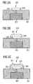
- an integrated circuit 302 is formed in a silicon substrate 301. Using a suitable etching process, a via hole is etched into the surface of the silicon substrate 301, and this contact hole is filled with a tungsten bonding member 303. Then the surface of the layer sequence thus obtained is covered with a continuous gold layer and using a lithography and an etching process, etches back the gold layer such that the gold base electrode 304 remains. As in 3A As shown, the gold ground electrode 304 is coupled to the integrated circuit 302 via the electrically conductive tungsten bonding pad 303.
- silver material 311 is deposited as the core of a reference electrode on the gold base electrode 304.
- this is realized by printing the gold base electrode 304 with a silver salt solution.
- the silver salt material is chemically reduced to elemental silver material, thereby illustratively forming a silver mirror 311.
- an ammoniacal silver nitrate solution (AgNO 3 with NH 3 ) and as a reducing agent, a glucose solution is used.
- the core of silver material 311 is chlorinated using a chemical process, thereby forming the silver chloride cladding 321.
- the chlorination is carried out by adding ferric chloride, whereby a thin, porous silver chloride layer 321 is formed.
- the silver core 311 and the silver chloride cladding 321 form a reference integrated electrode to which an electrical coupling to the integrated circuit 302 is realized by means of the electrically conductive base electrode 304 and by means of the electrically conductive tungsten contacting element 303.
- the integrated circuit 302 is set up in such a way that it can be provided by the reference electrode with a signal which is characteristic of the electrical potential in a surrounding region of the reference electrode.
- the process described is characterized by a particularly simple procedure: all substances are present in aqueous solution, which is why they are suitable for the printing processes also customary in biotechnology. In particular, expensive electrochemical processes (electroplating, chlorination) are dispensable, which is why the production method described is very cost-effective.
- the silver mirror 311 has a sufficiently good mechanical stability.
- the circuit arrangement 320 is suitable for being operated together with a biosensor, which may preferably also be integrated on or in the substrate 301.
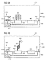
- Fig.4A to Fig.4C a designed as a biosensor arrangement 400 circuit arrangement according to a preferred embodiment of the invention described.
- macromolecular biomolecules can be detected using a reduction-oxidation-recycling method, wherein a reference electrode according to the invention keeps an analyte at a constant and defined electrical potential.
- the biosensor arrangement 400 is shown with a first working electrode 401 and a second working electrode 402 integrated in a silicon substrate 403.
- a holding area 404 made of gold material is applied on the first working electrode 401.
- the holding region 404 serves to immobilize DNA probe molecules 405 on the first working electrode 401.
- On the second working electrode 402, such a holding region is not provided.
- the biosensor arrangement 400 becomes one investigating solution, namely brought into contact with an electrolyte 406 such that DNA strands 407 possibly contained in the solution 406 to be investigated can hybridize with a sequence complementary to the sequence of the DNA probe molecules 405.
- an integrated reference electrode arrangement 415 is integrated in the silicon substrate 403.
- the integrated reference electrode arrangement 415 has a circuit 416 integrated in the silicon substrate 403. Further, the integrated reference electrode assembly 415 has a reference electrode formed of a silver core 418 formed on the silicon substrate 403 and partially surrounded by a silver chloride cladding 419 of sparingly soluble silver chloride salt.
- the integrated circuit 416 is electrically coupled to the silver core 418 via an electrically conductive tungsten coupling means 417.
- the integrated circuit 416 is arranged such that it is provided by the reference electrode a characteristic of the electrical potential of the electrolyte 406 signal.
- the circuit 416 is coupled via another tungsten coupling means 420 to a counterelectrode 421 arranged on the silicon substrate 403.
- the circuit 416 is further configured to provide a control signal to the counter electrode 421 immersed in the electrolyte 406 based on the detected potential. This is selected such that the electric potential of the electrolyte 406 is influenced by the counter electrode 421 such that the electric potential of the electrolyte 406 is equal to a reference value.
- FIG. 2 shows a scenario according to which DNA strands 407 to be detected in the solution to be examined 406 are included, one of which has hybridized with a DNA probe molecule 405.
- the DNA strands 407 in the zu are characterized with an enzyme 408, with which it is possible to cleave the molecules described below in electrochemically activated partial molecules.
- an enzyme 408 with which it is possible to cleave the molecules described below in electrochemically activated partial molecules.
- DNA probe molecules 405 are provided when DNA strands 407 to be detected are contained in the solution 406 to be investigated.
- a special flushing of the biosensor arrangement 400 is preferably carried out, wherein the rinsing solution used for this purpose is set up such that such DNA Strands on which a hybridization event has not occurred, are removed, and whereby the biosensor array 400 is cleaned of the solution 406 under investigation.
- the rinse solution used for rinsing is added to an electrochemically inactive substance which contains molecules which can be cleaved by means of the enzyme 408 into two partial molecules 410, of which at least one is electrochemically active and usually has an electrical charge.
- partial molecules 410 are, as in 4C drawn to the positively charged first working electrode 201, indicated by an arrow 411 in FIG 4C is indicated.
- the negatively charged partial molecules 410 are oxidized at the first working electrode 401, which has a positive electrical potential, and are drawn as oxidized partial molecules 413 to the negatively charged second working electrode 402, where they are again reduced.
- the reduced partial molecules 414 in turn migrate to the positively charged working electrode 401. In this way, an electrical circulating current is generated which is proportional to the number of charge carriers respectively generated by means of the enzymes 408.
- the oxidation and reduction potentials are to be controlled. For this it is necessary to apply a known electrical potential. Illustratively, this is done by means of the potentiostat device formed by the reference electrode, the counterelectrode 421 (and the working electrodes 401, 402).
- the functionality of the reference electrode assembly 415 according to the invention is essential to the functionality of the biosensor assembly 400.
Landscapes
- Health & Medical Sciences (AREA)
- Life Sciences & Earth Sciences (AREA)
- Immunology (AREA)
- Molecular Biology (AREA)
- Chemical & Material Sciences (AREA)
- Engineering & Computer Science (AREA)
- Physics & Mathematics (AREA)
- Biomedical Technology (AREA)
- Pathology (AREA)
- Hematology (AREA)
- General Physics & Mathematics (AREA)
- Analytical Chemistry (AREA)
- Urology & Nephrology (AREA)
- General Health & Medical Sciences (AREA)
- Biochemistry (AREA)
- Cell Biology (AREA)
- Medicinal Chemistry (AREA)
- Food Science & Technology (AREA)
- Microbiology (AREA)
- Biotechnology (AREA)
- Spectroscopy & Molecular Physics (AREA)
- Chemical Kinetics & Catalysis (AREA)
- Electrochemistry (AREA)
- Apparatus Associated With Microorganisms And Enzymes (AREA)
- Measuring Or Testing Involving Enzymes Or Micro-Organisms (AREA)
Claims (9)
- Procédé de fabrication d'un montage biocapteur-circuit• dans lequel on forme un circuit intégré dans un substrat ;• dans lequel on forme un noyau d'une électrode de référence intégrée au moyen d'une impression du substrat par du matériau d'argent en tant que métal ;• dans lequel on dépose des molécules biologiques au moyen d'une impression sur des champs de capteur du montage biocapteur-circuit de sorte que les champs de capteur sont activés biologiquement ;• dans lequel on effectue l'impression du substrat par du matériau d'argent et l'impression des champs de capteur par les molécules biologiques dans le même stade opératoire ;• dans lequel on entoure ensuite le noyau en matériau d'argent au moins en partie d'une enveloppe en un sel peu soluble du matériau d'argent, en formant ainsi l'électrode de référence intégrée ;• dans lequel on couple électriquement le circuit intégré au noyau de l'électrode de référence intégré.
- Procédé de fabrication d'un montage biocapteur-circuit• dans lequel on forme un circuit intégré dans un substrat ;• dans lequel on forme un noyau d'une électrode de référence intégrée en argent comme métal,o en imprimant le substrat par du matériau de sel d'argent ;o en réduisant chimiquement le matériau de sel d'argent en argent ;• dans lequel on dépose des molécules biologiques au moyen d'une impression sur des champs de capteur du montage biocapteur-circuit de sorte que les champs de capteur sont activés biologiquement ;• dans lequel on effectue l'impression du substrat par le noyau de l'électrode de référence intégré et l'impression des champs de capteur par les molécules biologiques et dans le même stade opératoire ;• dans lequel ensuite on entoure le noyau de l'électrode de référence intégrée au moins en partie d'une enveloppe en un sel d'argent peu soluble en tant que métal en formant ainsi l'électrode de référence intégrée ;• dans lequel on couple le circuit intégré au noyau de l'électrode de référence intégrée.
- Procédé suivant la revendication 1 ou 2,
dans lequel on forme une structure de couplage conductrice d'électricité de façon à coupler électriquement par celle-ci le circuit intégré au noyau. - Procédé suivant la revendication 3,
dans lequel on met la structure de couplage sur/ou dans le substrat de façon à ce que le noyau soit formé au moyen du recouvrement de la structure de couplage et/ou du substrat par le matériau d'argent ou par le matériau de sel d'argent. - Procédé suivant l'une des revendications 1 à 4,
dans lequel on utilise comme sel du métal le chlorure d'argent. - Procédé suivant l'une des revendications 1 à 5,
dans lequel on entoure au moins en partie le noyau de l'enveloppe en chlorant le noyau d'argent en utilisant• un procédé électrochimique ou• un procédé chimique. - Procédé suivant l'une des revendications 1 à 6,
dans lequel le circuit est tel qu'il peut lui être mis à disposition par l'électrode de référence un signal caractéristique du potentiel électrique dans une partie environnante de l'électrode de référence. - Procédé suivant l'une des revendications 1 à 7,
dans lequel on utilise comme substrat• un matériau semi-conducteur ;• du verre ;• de la matière plastique ; et/ou• de la céramique. - Procédé suivant l'une des revendications 3 à 8,
dans lequel la structure de couplage est en• or ; et/ou• platine
Applications Claiming Priority (3)
| Application Number | Priority Date | Filing Date | Title |
|---|---|---|---|
| DE10243569A DE10243569A1 (de) | 2002-09-19 | 2002-09-19 | Schaltkreis-Anordnung und Verfahren zum Herstellen einer Schaltkreis-Anordnung |
| DE10243569 | 2002-09-19 | ||
| PCT/DE2003/003123 WO2004029610A1 (fr) | 2002-09-19 | 2003-09-19 | Ensemble circuit avec électrode de référence intégrée et procédé de réalisation associé |
Publications (2)
| Publication Number | Publication Date |
|---|---|
| EP1540323A1 EP1540323A1 (fr) | 2005-06-15 |
| EP1540323B1 true EP1540323B1 (fr) | 2009-01-07 |
Family
ID=31969282
Family Applications (1)
| Application Number | Title | Priority Date | Filing Date |
|---|---|---|---|
| EP03769206A Expired - Lifetime EP1540323B1 (fr) | 2002-09-19 | 2003-09-19 | Procédé de fabrication d'un circuit pout bio-capteur comprenant une électrode de référence intégrée |
Country Status (5)
| Country | Link |
|---|---|
| US (1) | US20060258931A1 (fr) |
| EP (1) | EP1540323B1 (fr) |
| JP (1) | JP4307383B2 (fr) |
| DE (2) | DE10243569A1 (fr) |
| WO (1) | WO2004029610A1 (fr) |
Families Citing this family (1)
| Publication number | Priority date | Publication date | Assignee | Title |
|---|---|---|---|---|
| CN115186613B (zh) * | 2022-07-01 | 2026-01-09 | 郑州轻工业大学 | 一种搭建半加半减分子开关电路的方法 |
Citations (1)
| Publication number | Priority date | Publication date | Assignee | Title |
|---|---|---|---|---|
| WO1999019507A1 (fr) * | 1997-10-16 | 1999-04-22 | Abbott Laboratories | Mediateurs d'electrodes de biocapteur pour la regeneration de cofacteurs |
Family Cites Families (14)
| Publication number | Priority date | Publication date | Assignee | Title |
|---|---|---|---|---|
| JPS56146218A (en) * | 1980-04-15 | 1981-11-13 | Matsushita Electric Industrial Co Ltd | Method of manufacturing dielectric ceramic electronic part |
| US5509410A (en) * | 1983-06-06 | 1996-04-23 | Medisense, Inc. | Strip electrode including screen printing of a single layer |
| FR2554593B1 (fr) * | 1983-11-08 | 1986-09-19 | Comp Generale Electricite | Tete de dosage electrochimique a electrodes serigraphiees |
| US4874500A (en) * | 1987-07-15 | 1989-10-17 | Sri International | Microelectrochemical sensor and sensor array |
| US4836908A (en) * | 1987-12-22 | 1989-06-06 | Abbott Laboratories | Miniaturized reference electrodes |
| US5200051A (en) * | 1988-11-14 | 1993-04-06 | I-Stat Corporation | Wholly microfabricated biosensors and process for the manufacture and use thereof |
| GB2229005A (en) * | 1989-03-10 | 1990-09-12 | Plessey Co Plc | Biosensor device |
| EP0588153B1 (fr) * | 1992-09-14 | 1996-12-27 | Siemens Aktiengesellschaft | Capteur de gaz |
| GB9311035D0 (en) * | 1993-05-28 | 1993-07-14 | Environmental Med Prod | Electrochemical metal analysis |
| DE19621996C2 (de) * | 1996-05-31 | 1998-04-09 | Siemens Ag | Verfahren zur Herstellung einer Kombination eines Drucksensors und eines elektrochemischen Sensors |
| DE19621997C1 (de) * | 1996-05-31 | 1997-07-31 | Siemens Ag | Elektrochemischer Sensor |
| DE19623517C1 (de) * | 1996-06-12 | 1997-08-21 | Siemens Ag | MOS-Transistor für biotechnische Anwendungen |
| JP3063837B2 (ja) * | 1997-09-26 | 2000-07-12 | 日本電気株式会社 | 尿マルチセンサ |
| AU2001261145B2 (en) * | 2000-05-03 | 2005-08-11 | The United States Government, As Represented By The Department Of The Navy | Biological identification system with integrated sensor chip |
-
2002
- 2002-09-19 DE DE10243569A patent/DE10243569A1/de not_active Withdrawn
-
2003
- 2003-09-19 DE DE50311062T patent/DE50311062D1/de not_active Expired - Lifetime
- 2003-09-19 EP EP03769206A patent/EP1540323B1/fr not_active Expired - Lifetime
- 2003-09-19 US US10/528,504 patent/US20060258931A1/en not_active Abandoned
- 2003-09-19 JP JP2004538734A patent/JP4307383B2/ja not_active Expired - Fee Related
- 2003-09-19 WO PCT/DE2003/003123 patent/WO2004029610A1/fr not_active Ceased
Patent Citations (1)
| Publication number | Priority date | Publication date | Assignee | Title |
|---|---|---|---|---|
| WO1999019507A1 (fr) * | 1997-10-16 | 1999-04-22 | Abbott Laboratories | Mediateurs d'electrodes de biocapteur pour la regeneration de cofacteurs |
Also Published As
| Publication number | Publication date |
|---|---|
| DE10243569A1 (de) | 2004-04-01 |
| JP2005539239A (ja) | 2005-12-22 |
| DE50311062D1 (de) | 2009-02-26 |
| WO2004029610A1 (fr) | 2004-04-08 |
| EP1540323A1 (fr) | 2005-06-15 |
| US20060258931A1 (en) | 2006-11-16 |
| JP4307383B2 (ja) | 2009-08-05 |
Similar Documents
| Publication | Publication Date | Title |
|---|---|---|
| DE3752278T2 (de) | Verfahren für elektrochemische Messungen | |
| Deroco et al. | Electrochemical determination of capsaicin in pepper samples using sustainable paper-based screen-printed bulk modified with carbon black | |
| DE60125544T2 (de) | Elektrochemisches verfahren zur messung chemischer reaktionsraten | |
| de Oliveira et al. | Flow injection amperometric determination of isoniazid using a screen-printed carbon electrode modified with silver hexacyanoferrates nanoparticles | |
| Wang et al. | Screen-printed voltammetric sensor for TNT | |
| Suzuki et al. | An integrated three-electrode system with a micromachined liquid-junction Ag/AgCl reference electrode | |
| Oh et al. | Recent developments in electrochemical paper-based analytical devices | |
| DE112011105961T5 (de) | Nanolückenwandler mit Diamantelektroden | |
| US12523629B2 (en) | Nano- and/or micro-structured printed electrodes | |
| WO2009147093A1 (fr) | Procédé de détection d'espèces chimiques ou biologiques, et arrangement d'électrodes destiné à ce procédé | |
| Escarpa et al. | Agricultural and food electroanalysis | |
| US5830343A (en) | Electrochemical analysis process | |
| Redondo et al. | 3D-printed nanocarbon sensors for the detection of chlorophenols and nitrophenols: Towards environmental applications of additive manufacturing | |
| Sharafi et al. | A highly sensitive and ecofriendly assay platform for the simultaneous electrochemical determination of rifampicin and isoniazid in human serum and pharmaceutical formulations | |
| US8968825B1 (en) | Disposable palladium nanoparticle-modified graphite pencil electrode | |
| Siqueira et al. | Nanoporous gold microelectrode arrays using microchips: A highly sensitive and cost-effective platform for electroanalytical applications | |
| Feldman et al. | Electrochemical determination of low blood lead concentrations with a disposable carbon microarray electrode | |
| Pedre et al. | Electrochemical sensor for thiourea focused on metallurgical applications of copper | |
| EP1540323B1 (fr) | Procédé de fabrication d'un circuit pout bio-capteur comprenant une électrode de référence intégrée | |
| EP1738172B1 (fr) | Procede de fonctionnalisation de puces de biocapteurs | |
| EP3807626B1 (fr) | Biocapteur, procédé de détection utilisant ce biocapteur, procédé de fabrication et utilisation du biocapteur | |
| DE102004019641B4 (de) | FET-basierter Gassensor | |
| DE4232729C2 (de) | Mikrobezugselektrode zur Erzeugung eines konstanten Bezugs- oder Referenzpotentials | |
| DE102005003910B4 (de) | Elektrochemisches Transducer-Array und dessen Verwendung | |
| Bouchemel et al. | SnO-Sn (OH) 2 nanoflakes as non-enzymatic glucose sensor for human serum analysis using EIS |
Legal Events
| Date | Code | Title | Description |
|---|---|---|---|
| PUAI | Public reference made under article 153(3) epc to a published international application that has entered the european phase |
Free format text: ORIGINAL CODE: 0009012 |
|
| 17P | Request for examination filed |
Effective date: 20050311 |
|
| AK | Designated contracting states |
Kind code of ref document: A1 Designated state(s): AT BE BG CH CY CZ DE DK EE ES FI FR GB GR HU IE IT LI LU MC NL PT RO SE SI SK TR |
|
| RBV | Designated contracting states (corrected) |
Designated state(s): DE FR GB |
|
| RAP1 | Party data changed (applicant data changed or rights of an application transferred) |
Owner name: SIEMENS AKTIENGESELLSCHAFT |
|
| GRAP | Despatch of communication of intention to grant a patent |
Free format text: ORIGINAL CODE: EPIDOSNIGR1 |
|
| RTI1 | Title (correction) |
Free format text: METHOD FOR PRODUCING BIOSENSOR SWITCHING CIRCUIT ARRANGEMENT COMPRISING AN INTEGRATED REFERENCE ELECTRODE |
|
| GRAS | Grant fee paid |
Free format text: ORIGINAL CODE: EPIDOSNIGR3 |
|
| GRAA | (expected) grant |
Free format text: ORIGINAL CODE: 0009210 |
|
| AK | Designated contracting states |
Kind code of ref document: B1 Designated state(s): DE FR GB |
|
| REG | Reference to a national code |
Ref country code: GB Ref legal event code: FG4D Free format text: NOT ENGLISH |
|
| REF | Corresponds to: |
Ref document number: 50311062 Country of ref document: DE Date of ref document: 20090226 Kind code of ref document: P |
|
| PLBE | No opposition filed within time limit |
Free format text: ORIGINAL CODE: 0009261 |
|
| STAA | Information on the status of an ep patent application or granted ep patent |
Free format text: STATUS: NO OPPOSITION FILED WITHIN TIME LIMIT |
|
| PGFP | Annual fee paid to national office [announced via postgrant information from national office to epo] |
Ref country code: GB Payment date: 20090910 Year of fee payment: 7 |
|
| 26N | No opposition filed |
Effective date: 20091008 |
|
| GBPC | Gb: european patent ceased through non-payment of renewal fee |
Effective date: 20100919 |
|
| REG | Reference to a national code |
Ref country code: FR Ref legal event code: ST Effective date: 20110531 |
|
| PG25 | Lapsed in a contracting state [announced via postgrant information from national office to epo] |
Ref country code: FR Free format text: LAPSE BECAUSE OF NON-PAYMENT OF DUE FEES Effective date: 20100930 |
|
| PG25 | Lapsed in a contracting state [announced via postgrant information from national office to epo] |
Ref country code: GB Free format text: LAPSE BECAUSE OF NON-PAYMENT OF DUE FEES Effective date: 20100919 |
|
| PGFP | Annual fee paid to national office [announced via postgrant information from national office to epo] |
Ref country code: FR Payment date: 20091008 Year of fee payment: 7 |
|
| REG | Reference to a national code |
Ref country code: DE Ref legal event code: R081 Ref document number: 50311062 Country of ref document: DE Owner name: BOEHRINGER INGELHEIM VETMEDICA GMBH, DE Free format text: FORMER OWNER: SIEMENS AKTIENGESELLSCHAFT, 80333 MUENCHEN, DE Effective date: 20140612 |
|
| PGFP | Annual fee paid to national office [announced via postgrant information from national office to epo] |
Ref country code: DE Payment date: 20220620 Year of fee payment: 20 |
|
| REG | Reference to a national code |
Ref country code: DE Ref legal event code: R071 Ref document number: 50311062 Country of ref document: DE |