EP1540323B1 - Method for producing biosensor switching circuit arrangement comprising an integrated reference electrode - Google Patents
Method for producing biosensor switching circuit arrangement comprising an integrated reference electrode Download PDFInfo
- Publication number
- EP1540323B1 EP1540323B1 EP03769206A EP03769206A EP1540323B1 EP 1540323 B1 EP1540323 B1 EP 1540323B1 EP 03769206 A EP03769206 A EP 03769206A EP 03769206 A EP03769206 A EP 03769206A EP 1540323 B1 EP1540323 B1 EP 1540323B1
- Authority
- EP
- European Patent Office
- Prior art keywords
- silver
- reference electrode
- core
- substrate
- electrode
- Prior art date
- Legal status (The legal status is an assumption and is not a legal conclusion. Google has not performed a legal analysis and makes no representation as to the accuracy of the status listed.)
- Expired - Lifetime
Links
- 238000004519 manufacturing process Methods 0.000 title claims description 12
- BQCADISMDOOEFD-UHFFFAOYSA-N Silver Chemical compound [Ag] BQCADISMDOOEFD-UHFFFAOYSA-N 0.000 claims description 88
- 239000004332 silver Substances 0.000 claims description 61
- 229910052709 silver Inorganic materials 0.000 claims description 60
- 239000000758 substrate Substances 0.000 claims description 45
- 238000000034 method Methods 0.000 claims description 42
- HKZLPVFGJNLROG-UHFFFAOYSA-M silver monochloride Chemical compound [Cl-].[Ag+] HKZLPVFGJNLROG-UHFFFAOYSA-M 0.000 claims description 32
- 229910021607 Silver chloride Inorganic materials 0.000 claims description 31
- 239000000463 material Substances 0.000 claims description 28
- 238000007639 printing Methods 0.000 claims description 27
- 230000008878 coupling Effects 0.000 claims description 22
- 238000010168 coupling process Methods 0.000 claims description 22
- 238000005859 coupling reaction Methods 0.000 claims description 22
- GGCZERPQGJTIQP-UHFFFAOYSA-N sodium;9,10-dioxoanthracene-2-sulfonic acid Chemical compound [Na+].C1=CC=C2C(=O)C3=CC(S(=O)(=O)O)=CC=C3C(=O)C2=C1 GGCZERPQGJTIQP-UHFFFAOYSA-N 0.000 claims description 15
- 239000000126 substance Substances 0.000 claims description 13
- 229910052751 metal Inorganic materials 0.000 claims description 12
- 239000002184 metal Substances 0.000 claims description 12
- 150000003839 salts Chemical class 0.000 claims description 11
- PCHJSUWPFVWCPO-UHFFFAOYSA-N gold Chemical compound [Au] PCHJSUWPFVWCPO-UHFFFAOYSA-N 0.000 claims description 10
- 229910052737 gold Inorganic materials 0.000 claims description 10
- 239000010931 gold Substances 0.000 claims description 10
- BASFCYQUMIYNBI-UHFFFAOYSA-N platinum Chemical compound [Pt] BASFCYQUMIYNBI-UHFFFAOYSA-N 0.000 claims description 7
- 239000004065 semiconductor Substances 0.000 claims description 5
- 238000002848 electrochemical method Methods 0.000 claims description 4
- 239000000919 ceramic Substances 0.000 claims description 3
- 239000011521 glass Substances 0.000 claims description 3
- 239000004033 plastic Substances 0.000 claims description 3
- 229910052697 platinum Inorganic materials 0.000 claims description 3
- 238000003491 array Methods 0.000 claims 6
- 239000000243 solution Substances 0.000 description 29
- 108020004414 DNA Proteins 0.000 description 17
- 239000012491 analyte Substances 0.000 description 14
- 238000005516 engineering process Methods 0.000 description 14
- XUIMIQQOPSSXEZ-UHFFFAOYSA-N Silicon Chemical compound [Si] XUIMIQQOPSSXEZ-UHFFFAOYSA-N 0.000 description 11
- 239000003792 electrolyte Substances 0.000 description 11
- 230000008569 process Effects 0.000 description 11
- 229910052710 silicon Inorganic materials 0.000 description 11
- 239000010703 silicon Substances 0.000 description 11
- 238000005660 chlorination reaction Methods 0.000 description 10
- FAPWRFPIFSIZLT-UHFFFAOYSA-M Sodium chloride Chemical compound [Na+].[Cl-] FAPWRFPIFSIZLT-UHFFFAOYSA-M 0.000 description 9
- 239000012266 salt solution Substances 0.000 description 8
- 108020003215 DNA Probes Proteins 0.000 description 7
- 239000003298 DNA probe Substances 0.000 description 7
- 238000005253 cladding Methods 0.000 description 7
- 229910052721 tungsten Inorganic materials 0.000 description 7
- 239000010937 tungsten Substances 0.000 description 7
- KWYUFKZDYYNOTN-UHFFFAOYSA-M Potassium hydroxide Chemical compound [OH-].[K+] KWYUFKZDYYNOTN-UHFFFAOYSA-M 0.000 description 6
- HEMHJVSKTPXQMS-UHFFFAOYSA-M Sodium hydroxide Chemical compound [OH-].[Na+] HEMHJVSKTPXQMS-UHFFFAOYSA-M 0.000 description 6
- 239000003638 chemical reducing agent Substances 0.000 description 6
- WFKWXMTUELFFGS-UHFFFAOYSA-N tungsten Chemical compound [W] WFKWXMTUELFFGS-UHFFFAOYSA-N 0.000 description 6
- VEXZGXHMUGYJMC-UHFFFAOYSA-M Chloride anion Chemical compound [Cl-] VEXZGXHMUGYJMC-UHFFFAOYSA-M 0.000 description 5
- 102000004190 Enzymes Human genes 0.000 description 5
- 108090000790 Enzymes Proteins 0.000 description 5
- WCUXLLCKKVVCTQ-UHFFFAOYSA-M Potassium chloride Chemical compound [Cl-].[K+] WCUXLLCKKVVCTQ-UHFFFAOYSA-M 0.000 description 5
- 239000007864 aqueous solution Substances 0.000 description 5
- RBTARNINKXHZNM-UHFFFAOYSA-K iron trichloride Chemical compound Cl[Fe](Cl)Cl RBTARNINKXHZNM-UHFFFAOYSA-K 0.000 description 5
- 238000002493 microarray Methods 0.000 description 5
- 229910021578 Iron(III) chloride Inorganic materials 0.000 description 4
- 230000008901 benefit Effects 0.000 description 4
- 239000000460 chlorine Substances 0.000 description 4
- XEEYBQQBJWHFJM-UHFFFAOYSA-N iron Substances [Fe] XEEYBQQBJWHFJM-UHFFFAOYSA-N 0.000 description 4
- 238000004064 recycling Methods 0.000 description 4
- 239000003124 biologic agent Substances 0.000 description 3
- 238000001311 chemical methods and process Methods 0.000 description 3
- 238000006243 chemical reaction Methods 0.000 description 3
- 238000004140 cleaning Methods 0.000 description 3
- 238000000840 electrochemical analysis Methods 0.000 description 3
- 238000009713 electroplating Methods 0.000 description 3
- 239000000203 mixture Substances 0.000 description 3
- 238000006722 reduction reaction Methods 0.000 description 3
- 239000000523 sample Substances 0.000 description 3
- HAAYBYDROVFKPU-UHFFFAOYSA-N silver;azane;nitrate Chemical compound N.N.[Ag+].[O-][N+]([O-])=O HAAYBYDROVFKPU-UHFFFAOYSA-N 0.000 description 3
- 239000011734 sodium Substances 0.000 description 3
- 239000011780 sodium chloride Substances 0.000 description 3
- 101710134784 Agnoprotein Proteins 0.000 description 2
- 238000000018 DNA microarray Methods 0.000 description 2
- WQZGKKKJIJFFOK-GASJEMHNSA-N Glucose Natural products OC[C@H]1OC(O)[C@H](O)[C@@H](O)[C@@H]1O WQZGKKKJIJFFOK-GASJEMHNSA-N 0.000 description 2
- OAKJQQAXSVQMHS-UHFFFAOYSA-N Hydrazine Chemical compound NN OAKJQQAXSVQMHS-UHFFFAOYSA-N 0.000 description 2
- UFHFLCQGNIYNRP-UHFFFAOYSA-N Hydrogen Chemical compound [H][H] UFHFLCQGNIYNRP-UHFFFAOYSA-N 0.000 description 2
- 230000002378 acidificating effect Effects 0.000 description 2
- 150000001450 anions Chemical class 0.000 description 2
- 230000000295 complement effect Effects 0.000 description 2
- 239000007822 coupling agent Substances 0.000 description 2
- 230000008021 deposition Effects 0.000 description 2
- 238000001514 detection method Methods 0.000 description 2
- 238000005530 etching Methods 0.000 description 2
- 239000007789 gas Substances 0.000 description 2
- 239000008103 glucose Substances 0.000 description 2
- 239000001257 hydrogen Substances 0.000 description 2
- 229910052739 hydrogen Inorganic materials 0.000 description 2
- 150000002500 ions Chemical class 0.000 description 2
- 229910000510 noble metal Inorganic materials 0.000 description 2
- 239000003960 organic solvent Substances 0.000 description 2
- 230000003647 oxidation Effects 0.000 description 2
- 238000007254 oxidation reaction Methods 0.000 description 2
- 239000002245 particle Substances 0.000 description 2
- 239000001103 potassium chloride Substances 0.000 description 2
- 235000011164 potassium chloride Nutrition 0.000 description 2
- 230000009467 reduction Effects 0.000 description 2
- -1 silver ions Chemical class 0.000 description 2
- JKFYKCYQEWQPTM-UHFFFAOYSA-N 2-azaniumyl-2-(4-fluorophenyl)acetate Chemical compound OC(=O)C(N)C1=CC=C(F)C=C1 JKFYKCYQEWQPTM-UHFFFAOYSA-N 0.000 description 1
- OKTJSMMVPCPJKN-UHFFFAOYSA-N Carbon Chemical compound [C] OKTJSMMVPCPJKN-UHFFFAOYSA-N 0.000 description 1
- ZAMOUSCENKQFHK-UHFFFAOYSA-N Chlorine atom Chemical compound [Cl] ZAMOUSCENKQFHK-UHFFFAOYSA-N 0.000 description 1
- 102000053602 DNA Human genes 0.000 description 1
- DGAQECJNVWCQMB-PUAWFVPOSA-M Ilexoside XXIX Chemical compound C[C@@H]1CC[C@@]2(CC[C@@]3(C(=CC[C@H]4[C@]3(CC[C@@H]5[C@@]4(CC[C@@H](C5(C)C)OS(=O)(=O)[O-])C)C)[C@@H]2[C@]1(C)O)C)C(=O)O[C@H]6[C@@H]([C@H]([C@@H]([C@H](O6)CO)O)O)O.[Na+] DGAQECJNVWCQMB-PUAWFVPOSA-M 0.000 description 1
- 239000000020 Nitrocellulose Substances 0.000 description 1
- ZLMJMSJWJFRBEC-UHFFFAOYSA-N Potassium Chemical compound [K] ZLMJMSJWJFRBEC-UHFFFAOYSA-N 0.000 description 1
- 229910021612 Silver iodide Inorganic materials 0.000 description 1
- 230000003213 activating effect Effects 0.000 description 1
- 239000013543 active substance Substances 0.000 description 1
- 230000003321 amplification Effects 0.000 description 1
- 238000004458 analytical method Methods 0.000 description 1
- 238000013459 approach Methods 0.000 description 1
- QZPSXPBJTPJTSZ-UHFFFAOYSA-N aqua regia Chemical compound Cl.O[N+]([O-])=O QZPSXPBJTPJTSZ-UHFFFAOYSA-N 0.000 description 1
- 238000012742 biochemical analysis Methods 0.000 description 1
- 229940075397 calomel Drugs 0.000 description 1
- 229910052799 carbon Inorganic materials 0.000 description 1
- 239000002800 charge carrier Substances 0.000 description 1
- 229910052801 chlorine Inorganic materials 0.000 description 1
- 239000011248 coating agent Substances 0.000 description 1
- 238000000576 coating method Methods 0.000 description 1
- 230000001419 dependent effect Effects 0.000 description 1
- 238000013461 design Methods 0.000 description 1
- 238000011161 development Methods 0.000 description 1
- 230000018109 developmental process Effects 0.000 description 1
- ZOMNIUBKTOKEHS-UHFFFAOYSA-L dimercury dichloride Chemical compound Cl[Hg][Hg]Cl ZOMNIUBKTOKEHS-UHFFFAOYSA-L 0.000 description 1
- 238000001035 drying Methods 0.000 description 1
- 230000000694 effects Effects 0.000 description 1
- 239000012799 electrically-conductive coating Substances 0.000 description 1
- 230000005518 electrochemistry Effects 0.000 description 1
- 239000007772 electrode material Substances 0.000 description 1
- 238000011010 flushing procedure Methods 0.000 description 1
- 238000010438 heat treatment Methods 0.000 description 1
- 238000009396 hybridization Methods 0.000 description 1
- 238000011835 investigation Methods 0.000 description 1
- 239000004922 lacquer Substances 0.000 description 1
- 239000003446 ligand Substances 0.000 description 1
- 239000007788 liquid Substances 0.000 description 1
- 238000001459 lithography Methods 0.000 description 1
- 239000011159 matrix material Substances 0.000 description 1
- 229910021645 metal ion Inorganic materials 0.000 description 1
- 239000007769 metal material Substances 0.000 description 1
- 229920001220 nitrocellulos Polymers 0.000 description 1
- 238000003199 nucleic acid amplification method Methods 0.000 description 1
- 229910052700 potassium Inorganic materials 0.000 description 1
- 239000011591 potassium Substances 0.000 description 1
- 239000002244 precipitate Substances 0.000 description 1
- 239000000376 reactant Substances 0.000 description 1
- 230000009257 reactivity Effects 0.000 description 1
- 239000012487 rinsing solution Substances 0.000 description 1
- 238000007650 screen-printing Methods 0.000 description 1
- 229940045105 silver iodide Drugs 0.000 description 1
- 229910052708 sodium Inorganic materials 0.000 description 1
- 239000007790 solid phase Substances 0.000 description 1
Images

Classifications
-
- G—PHYSICS
- G01—MEASURING; TESTING
- G01N—INVESTIGATING OR ANALYSING MATERIALS BY DETERMINING THEIR CHEMICAL OR PHYSICAL PROPERTIES
- G01N33/00—Investigating or analysing materials by specific methods not covered by groups G01N1/00 - G01N31/00
- G01N33/48—Biological material, e.g. blood, urine; Haemocytometers
- G01N33/50—Chemical analysis of biological material, e.g. blood, urine; Testing involving biospecific ligand binding methods; Immunological testing
- G01N33/53—Immunoassay; Biospecific binding assay; Materials therefor
- G01N33/543—Immunoassay; Biospecific binding assay; Materials therefor with an insoluble carrier for immobilising immunochemicals
- G01N33/54366—Apparatus specially adapted for solid-phase testing
- G01N33/54373—Apparatus specially adapted for solid-phase testing involving physiochemical end-point determination, e.g. wave-guides, FETS, gratings
- G01N33/5438—Electrodes
-
- G—PHYSICS
- G01—MEASURING; TESTING
- G01N—INVESTIGATING OR ANALYSING MATERIALS BY DETERMINING THEIR CHEMICAL OR PHYSICAL PROPERTIES
- G01N27/00—Investigating or analysing materials by the use of electric, electrochemical, or magnetic means
- G01N27/26—Investigating or analysing materials by the use of electric, electrochemical, or magnetic means by investigating electrochemical variables; by using electrolysis or electrophoresis
- G01N27/28—Electrolytic cell components
- G01N27/30—Electrodes, e.g. test electrodes; Half-cells
- G01N27/327—Biochemical electrodes, e.g. electrical or mechanical details for in vitro measurements
- G01N27/3275—Sensing specific biomolecules, e.g. nucleic acid strands, based on an electrode surface reaction
- G01N27/3277—Sensing specific biomolecules, e.g. nucleic acid strands, based on an electrode surface reaction being a redox reaction, e.g. detection by cyclic voltammetry
Definitions
- the invention relates to a method for producing a biosensor circuit arrangement.
- electrochemical methods are often used to obtain qualitative or quantitative information about a concentration of a redox-active substance in an analyte.
- the reduction or oxidation potentials of the substances to be investigated and electrical current values occurring at electrodes are frequently determined and evaluated.
- E is the electrical potential of a redox system
- E 0 is a standard electrical potential
- R is the gas constant
- T is the absolute temperature
- n is the electrochemical valence
- F is the Faraday constant
- [Ox] is the concentration of the oxidized form
- [Red ] the concentration of the reduced form of the redox substance.
- Such a reference potential is provided by means of a reference electrode.
- a reference electrode of the first kind the electrical potential is determined by the electrochemical equilibrium between the material of the electrode and its ions in the solution.
- the metal ions in the solution have a decisive influence on the electrical potential.
- An example of a reference electrode of the first type is the hydrogen electrode.
- an electrically conductive structure allows the charge exchange between two media.
- a reference electrode of the second kind there is known an arrangement in which the concentration of ions determining electric potential is determined by the presence of a sparingly soluble equi-ionic compound which provides a second solid phase.
- a reference electrode of the second kind is a metal which is covered with a layer of a sparingly soluble salt of the metal and immersed in the solution of an easily soluble salt having a common anion with the sparingly soluble salt.
- the electrode potential is determined by the activity of the anions of the easily soluble salt.
- Examples of reference electrodes of the second kind are the calomel electrode or the silver / silver chloride electrode.
- One embodiment of a silver / silver chloride electrode has a silver chloride-coated silver wire immersed in a chloride ion-containing solution.
- the concentration of silver ions is very small and due to the balance due to the presence of the chloride ions in the solution Ag + + Cl - ⁇ AgCl (2) established.
- electrochemical analysis methods use macroscopic reference electrodes, in particular a silver / silver chloride electrode, which are brought into operative contact with the analyte.
- Typical dimensions of such electrodes range from several centimeters to a few millimeters.
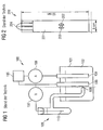
- a prior art electrochemical experimental assembly 100 is shown.
- a container 101 an analyte 102 is filled, which is examined by means of working electrodes 103, 104 electrochemically.
- the first working electrode 103 is coupled to a power supply 105, whereas the second working electrode 104 is coupled to an ammeter 106.
- a voltmeter 107 is connected between the first working electrode 103 and a silver wire-coated silver wire 110 of a silver / silver chloride electrode assembly 109.
- the analyte 102 is brought into operative contact with the silver / silver chloride electrode assembly 109.
- the analyte 102 of the electrochemical experimental assembly 100 is provided with an electrical reference potential.
- the experimental arrangement is arranged to examine the analyte 102, and by means of the silver / silver chloride electrode arrangement 109 a reference potential is provided for the examination.
- silver / silver chloride reference electrode 109 has the disadvantage that a significant minimum volume of the analyte 102 is required to reliably bring the macroscopic reference electrode with the analyte 102 in operative contact. Furthermore, the mechanical structure of the silver / silver chloride electrode assembly 109 is expensive, which is why such reference electrodes only be used in laboratory systems. In particular, for biosensory applications, the silver / silver chloride electrode assembly 109 is unsuitable, since in biology usually only small sample volumes are available.
- Fig.2 a sensor arrangement 200 known from [1] for electrochemical measurements, which has a reference electrode.
- the sensor arrangement 200 has a dimension of 8 mm by 50 mm and has a working electrode 201, a counterelectrode 202 and a reference electrode 203. Furthermore, contacts 204 are provided by means of which the sensor arrangement 200 can be coupled to a control circuit is.
- the sensor arrangement 200 has a three-electrode arrangement common in electrochemistry with the electrodes 201, 202, 203 and is produced using a screen-printing method.
- the working electrode 201 is made of carbon, whereas the counter electrode 202 and the reference electrode 203 are each formed as a silver / silver chloride electrode.
- the analyte is pipetted onto the electrodes 201 to 203, whereby a volume of at least 15 ⁇ l is required.
- sample volumes are often not available, especially in biological studies with sufficiently strong sample concentration.
- a chlorinated silver wire is often used as a reference electrode, since one can be formed in a relatively small size.
- a silver wire or a silver-plated platinum wire is surface-chlorinated and then brought into operative contact with an analyte.
- this is a reference electrode with dimension in the millimeter range, an even greater miniaturization is not possible. Therefore, the Dri-Ref TM reference electrodes known from [2] are primarily suitable for laboratory use, whereas they are unsuitable for commercial applications.
- the knowledge of the electrical potential of an electrolyte is important. Therefore, a reference electrode is required in a DNA sensor array when electrochemical analysis methods are used.
- the diameter of the biologically activated region of a sensor array is often between 100 ⁇ m and 200 ⁇ m with typically ten to one hundred DNA sensors per mm 2 of substrate surface area.
- WO 99/19057 discloses a method of making a biosensor circuit assembly wherein reference and bio molecular columns are printed on a substrate.
- EP 0 299 778 A2 discloses a method of making an electrochemical microsensor containing a reference electrode and electrode structures having printed biologically active molecules.
- the invention is based on the problem to provide a cost-effective and producible with reasonable effort reference electrode, which is also suitable for applications of biosensing.
- a miniaturized, monolithically integrated reference electrode of the second type is formed, wherein the integrated circuit of the circuit arrangement is electrically coupled to the reference electrode of the second type, so that the reference electrode can be brought to an electrical reference potential.
- the electrochemical reference electrode according to the invention is particularly tailored to the needs of highly integrated electrochemical analysis systems.
- the reference electrode of the invention can advantageously be used on the surface of a sensor arrangement designed as a circuit arrangement, and can in particular be formed with dimensions comparable to integrated components (eg an integrated biosensor element).
- the cost of producing the circuit arrangement according to the invention is low, so that the reference electrode is particularly suitable for mass production, eg of biosensor arrangements.
- a reference potential can be provided with little effort and with high accuracy.
- the miniaturized reference electrode (which can be configured in particular as a silver / silver chloride reference electrode) can be produced with little effort (for example using simple printing or electrochemical methods). To produce the electrode complex and therefore cost-intensive process techniques of the semiconductor industry are unnecessary.
- the integrated circuit can be set up in such a way that it can be provided by the reference electrode with a signal which is characteristic of the electrical potential in a surrounding region of the reference electrode.
- the reference electrode may detect the electric potential in its surrounding area (the surrounding area is, for example, an electrolyte in which the reference electrode is immersed) and provide a corresponding signal to the circuit.
- the circuit may be further configured to provide, for example, a control signal to a counter electrode immersed, for example, in the electrolyte based on the detected potential, which is selected such that the electrical potential of the electrolyte is influenced by the counter electrode (eg, the potential the value of a reference potential is set).
- the coupling between the integrated circuit and the core of the reference electrode can be realized as a direct coupling of an electrically conductive coupling means of the integrated circuit with the metallic core of the reference electrode.
- the circuit arrangement may comprise an electrically conductive coupling structure, by means of which the integrated circuit is electrically coupled to the metallic core.
- the coupling structure is preferably made of a chemically inert material such as gold or platinum.
- the metal of the core of the reference electrode is silver, and the salt of the metal is preferably Silver chloride. Then, the reference electrode is designed as a silver / silver chloride reference electrode. Alternatively, however, any other metal-metal salt combination is suitable, provided that the salt is sufficiently sparingly soluble (for example silver / silver iodide).
- the substrate may comprise, for example, a semiconductor material (in particular silicon), glass, plastic and / or ceramic.
- a semiconductor material in particular silicon
- glass glass
- plastic plastic
- / or ceramic Preferably, the substrate is a silicon wafer.
- the circuit arrangement is set up as a sensor arrangement.
- the reference electrode of the circuit arrangement may serve to keep an electrical potential of the sensor arrangement constant.
- the circuit arrangement is set up as a biosensor arrangement.
- the circuit arrangement may be a biosensor array for DNA analysis using an electrochemical process (e.g., redox recycling).
- the reference potential required for the operation of the potentiostats contained on a semiconductor chip as a substrate can be provided by using the reference electrode according to the invention.
- An electrically conductive coupling structure may be formed so as to electrically couple the integrated circuit to the core.
- silver is used as the metallic material of the core.
- silver chloride is preferably used as a salt of the metal to form the cladding of the metallic core.
- the core is formed by printing the substrate and / or the coupling structure with silver material.
- the core may be formed by printing the substrate and / or the coupling structure with silver salt material using a per se known printing technique and chemically reducing the silver salt material to silver.
- the core may be at least partially surrounded by the shell by chlorinating the core of silver using an electrochemical process or a chemical process.
- the method according to the invention makes it possible to integrate a reference electrode on and / or in the substrate. As a result, a subsequent, consuming attaching the reference electrode is unnecessary.
- Suitable substrates are all materials on which electrically conductive structures can be applied as a component of the reference electrode, such as glass, ceramic, plastic. Preference is given to using a semiconductor substrate with which it is possible to require the operation of a sensor arrangement or to provide a constant voltage to integrate electrical circuit, preferably in CMOS technology.
- an electrically conductive coupling structure (illustratively also called ground electrode) is applied to the chip surface.
- the base electrode By means of the base electrode, an electrical contact between the reference electrode to be formed and the integrated circuit in the substrate can be realized.
- the base electrode is made of a chemically inert material such as gold or platinum.
- the reference electrode of the invention in the design of the circuit arrangement as a biosensor arrangement, it is advantageous to form the reference electrode of the invention in the same operation and using the same or a similar device with which the surface of the substrate is biologically activated.
- a printable reference electrode is advantageous.
- a circuit arrangement according to the invention which has a reference electrode made of a silver core and a silver chloride cladding, first the core of silver is formed on the substrate. The silver core is then at least partially surrounded by a shell of poorly soluble silver chloride.
- the silver core will be formed by printing the substrate (or by printing a previously formed coupling structure on the substrate to make electrical coupling between the integrated circuit of the substrate and the silver core) with silver material.
- a solution of silver particles in a nitrocellulose lacquer is printed on the substrate or on the coupling structure (base electrode), wherein the above-described stamp method or the above-described ink-jet method can be used.
- an electrically conductive coating forms on the substrate or on the base electrode.
- This coating can serve directly as a metal core of the reference electrode or, alternatively, can also be galvanically reinforced.
- the resulting layer sequence is immersed in a solution of a silver salt, and an electrical voltage is applied to the metallic core. This voltage can be achieved, for example, by using the functionality of the integrated one already formed in the substrate Circuit are created.
- the shape of the formed reference electrode can be flexibly adjusted by adjusting the printing operation.
- This method has the advantage that the same printing technology can be used to apply the silver core as it is used to biologically activate a sensor array.
- the silver core of the reference electrode is applied in the same step, in which the sensor fields of a circuit arrangement designed as a biosensor arrangement are provided with suitable capture molecules (for example DNA half-strands).
- suitable capture molecules for example DNA half-strands.
- a special cleaning step of the printhead may be required if the application of silver material to the substrate or to the base electrode is realized using an organic solution of silver particles, whereas biological agents often use an aqueous solution of the biomolecules becomes.
- the silver core is formed by printing the substrate and / or the base electrode with silver salt material and the silver salt. Material is chemically reduced to silver.
- a silver salt solution is printed on the base electrode, for example, an ammoniacal silver nitrate solution, and immediately thereafter, a reducing agent, for example a hydrazine solution (H 2 N-NH 2 ) was added.
- a reducing agent for example a hydrazine solution (H 2 N-NH 2 ) was added.
- This method has the significant advantage that electroplating is unnecessary to deposit a closed silver layer on the base electrode.
- the quality of the silver layer depends strongly on the chemical conditions under which the reduction reaction takes place and on the nature of the surface on which the silver mirror is deposited.
- the geometric shape of a reference electrode formed in this way is determined by the geometric shape of the printed silver salt solution and can be formed independently of the shape of the base electrode.
- the silver salt solution on the one hand and the reducing agent on the other hand can also be printed in already mixed form. If an ammoniacal silver nitrate solution (AgNO 3 with NH 3 ) is mixed with glucose solution and this mixture is printed on the base electrode, a silver level is deposited on the printed surface. This reaction is significantly accelerated by the mixture is heated after printing or printed on an already heated surface. If silver salt solution and reducing agent are printed successively, then by means of a suitable choice of substance, in particular of the reducing agent, and by adjusting the concentrations, the deposition of the silver level can be considerably accelerated so that heating of the mixture for silvering is dispensable.
- an ammoniacal silver nitrate solution AgNO 3 with NH 3
- This method also has the great advantage that the same printing technology used for biologically activating the sensor fields (eg application of DNA half-strands) can be used to apply the silver electrode. Ideally, the silver electrode can even be applied in the same work step as the biological molecules. Furthermore, it is advantageous that it is exclusively an aqueous solution of the substances used, so that no special measures are required for cleaning the print head, as is the case for example with the use of organic solvents.
- the silver core is immersed in a chloride ion-containing solution, for example, sodium chloride (NaCl) or potassium chloride (KCl). Since silver is a relatively noble metal, an electrical voltage is preferably applied to the electrodes, so that the reaction Ag + Cl - ⁇ AgCl + e - (3) runs fast enough.
- a chloride ion-containing solution for example, sodium chloride (NaCl) or potassium chloride (KCl).
- an electrical voltage is preferably applied to the electrodes, so that the reaction Ag + Cl - ⁇ AgCl + e - (3) runs fast enough.
- sodium (Na + + e - ⁇ Na) or potassium material (K + + e - ⁇ K) reacted in the aqueous solution to sodium hydroxide (NaOH) or potassium hydroxide to (KOH) where hydrogen is released: 2Na + 2H 2 O ⁇ 2NaOH + H 2 (4) respectively.
- the chlorination of the silver core is preferably carried out before the chips are sawn out of a wafer.
- suitable electrically conductive coupling means between the chip on the wafer first of all basic electrodes (or a part of the basic electrodes) electrically coupled together.
- a suitable chloride ion-containing saline solution By immersing the wafer in a suitable chloride ion-containing saline solution and applying a suitable voltage to the electrode assembly thus formed all silver electrodes of all the chips of the wafer are chlorinated in a common process step.
- the electrical couplings between the ground electrodes are automatically cut through.
- the galvanic chlorination of the silver electrode can be realized on the single chip, if several electrodes are sufficiently close to each other on the chip electrode.
- a chloride-containing saline solution for example NaCl or KCl solution
- a positive electrical potential is applied to the silver cores (preferably using the integrated circuits coupled thereto), and one of the other electrodes, which is also coated with the saline solution is in active contact, is used as a counter-electrode.
- the silver core may be at least partially surrounded by the shell by chlorinating the silver core using a chemical process.
- the chemical chlorination can be realized by immersing the silver core, for example, in an acidic ferric chloride solution, thereby causing a chlorination reaction of the silver.
- the redox system Ag / Ag + has a normal potential of 0.799V
- the redox system Ag / AgCl has a standard potential of only 0.222V. This means that the silver core can be chlorinated by simply printing out an acidic ferric chloride solution (FeCl 3 ).
- This method also has the advantage that the same printing technology used to biologically activate sensor fields is used to chlorinate the silver core.
- the iron (III) chloride solution can be applied in the same work step as the biologically active capture molecules.
- the direct chlorination of the silver electrode are used in the substances containing elemental chlorine, such as aqua regia (HNO 3 + 3HCl). Due to the high reactivity of such substances special measures are necessary in particular during printing.
- elemental chlorine such as aqua regia (HNO 3 + 3HCl). Due to the high reactivity of such substances special measures are necessary in particular during printing.
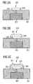
- an integrated circuit 302 is formed in a silicon substrate 301. Using a suitable etching process, a via hole is etched into the surface of the silicon substrate 301, and this contact hole is filled with a tungsten bonding member 303. Then the surface of the layer sequence thus obtained is covered with a continuous gold layer and using a lithography and an etching process, etches back the gold layer such that the gold base electrode 304 remains. As in 3A As shown, the gold ground electrode 304 is coupled to the integrated circuit 302 via the electrically conductive tungsten bonding pad 303.
- silver material 311 is deposited as the core of a reference electrode on the gold base electrode 304.
- this is realized by printing the gold base electrode 304 with a silver salt solution.
- the silver salt material is chemically reduced to elemental silver material, thereby illustratively forming a silver mirror 311.
- an ammoniacal silver nitrate solution (AgNO 3 with NH 3 ) and as a reducing agent, a glucose solution is used.
- the core of silver material 311 is chlorinated using a chemical process, thereby forming the silver chloride cladding 321.
- the chlorination is carried out by adding ferric chloride, whereby a thin, porous silver chloride layer 321 is formed.
- the silver core 311 and the silver chloride cladding 321 form a reference integrated electrode to which an electrical coupling to the integrated circuit 302 is realized by means of the electrically conductive base electrode 304 and by means of the electrically conductive tungsten contacting element 303.
- the integrated circuit 302 is set up in such a way that it can be provided by the reference electrode with a signal which is characteristic of the electrical potential in a surrounding region of the reference electrode.
- the process described is characterized by a particularly simple procedure: all substances are present in aqueous solution, which is why they are suitable for the printing processes also customary in biotechnology. In particular, expensive electrochemical processes (electroplating, chlorination) are dispensable, which is why the production method described is very cost-effective.
- the silver mirror 311 has a sufficiently good mechanical stability.
- the circuit arrangement 320 is suitable for being operated together with a biosensor, which may preferably also be integrated on or in the substrate 301.
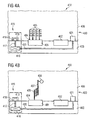
- Fig.4A to Fig.4C a designed as a biosensor arrangement 400 circuit arrangement according to a preferred embodiment of the invention described.
- macromolecular biomolecules can be detected using a reduction-oxidation-recycling method, wherein a reference electrode according to the invention keeps an analyte at a constant and defined electrical potential.
- the biosensor arrangement 400 is shown with a first working electrode 401 and a second working electrode 402 integrated in a silicon substrate 403.
- a holding area 404 made of gold material is applied on the first working electrode 401.
- the holding region 404 serves to immobilize DNA probe molecules 405 on the first working electrode 401.
- On the second working electrode 402, such a holding region is not provided.
- the biosensor arrangement 400 becomes one investigating solution, namely brought into contact with an electrolyte 406 such that DNA strands 407 possibly contained in the solution 406 to be investigated can hybridize with a sequence complementary to the sequence of the DNA probe molecules 405.
- an integrated reference electrode arrangement 415 is integrated in the silicon substrate 403.
- the integrated reference electrode arrangement 415 has a circuit 416 integrated in the silicon substrate 403. Further, the integrated reference electrode assembly 415 has a reference electrode formed of a silver core 418 formed on the silicon substrate 403 and partially surrounded by a silver chloride cladding 419 of sparingly soluble silver chloride salt.
- the integrated circuit 416 is electrically coupled to the silver core 418 via an electrically conductive tungsten coupling means 417.
- the integrated circuit 416 is arranged such that it is provided by the reference electrode a characteristic of the electrical potential of the electrolyte 406 signal.
- the circuit 416 is coupled via another tungsten coupling means 420 to a counterelectrode 421 arranged on the silicon substrate 403.
- the circuit 416 is further configured to provide a control signal to the counter electrode 421 immersed in the electrolyte 406 based on the detected potential. This is selected such that the electric potential of the electrolyte 406 is influenced by the counter electrode 421 such that the electric potential of the electrolyte 406 is equal to a reference value.
- FIG. 2 shows a scenario according to which DNA strands 407 to be detected in the solution to be examined 406 are included, one of which has hybridized with a DNA probe molecule 405.
- the DNA strands 407 in the zu are characterized with an enzyme 408, with which it is possible to cleave the molecules described below in electrochemically activated partial molecules.
- an enzyme 408 with which it is possible to cleave the molecules described below in electrochemically activated partial molecules.
- DNA probe molecules 405 are provided when DNA strands 407 to be detected are contained in the solution 406 to be investigated.
- a special flushing of the biosensor arrangement 400 is preferably carried out, wherein the rinsing solution used for this purpose is set up such that such DNA Strands on which a hybridization event has not occurred, are removed, and whereby the biosensor array 400 is cleaned of the solution 406 under investigation.
- the rinse solution used for rinsing is added to an electrochemically inactive substance which contains molecules which can be cleaved by means of the enzyme 408 into two partial molecules 410, of which at least one is electrochemically active and usually has an electrical charge.
- partial molecules 410 are, as in 4C drawn to the positively charged first working electrode 201, indicated by an arrow 411 in FIG 4C is indicated.
- the negatively charged partial molecules 410 are oxidized at the first working electrode 401, which has a positive electrical potential, and are drawn as oxidized partial molecules 413 to the negatively charged second working electrode 402, where they are again reduced.
- the reduced partial molecules 414 in turn migrate to the positively charged working electrode 401. In this way, an electrical circulating current is generated which is proportional to the number of charge carriers respectively generated by means of the enzymes 408.
- the oxidation and reduction potentials are to be controlled. For this it is necessary to apply a known electrical potential. Illustratively, this is done by means of the potentiostat device formed by the reference electrode, the counterelectrode 421 (and the working electrodes 401, 402).
- the functionality of the reference electrode assembly 415 according to the invention is essential to the functionality of the biosensor assembly 400.
Landscapes
- Health & Medical Sciences (AREA)
- Life Sciences & Earth Sciences (AREA)
- Immunology (AREA)
- Molecular Biology (AREA)
- Chemical & Material Sciences (AREA)
- Engineering & Computer Science (AREA)
- Physics & Mathematics (AREA)
- Biomedical Technology (AREA)
- Pathology (AREA)
- Hematology (AREA)
- General Physics & Mathematics (AREA)
- Analytical Chemistry (AREA)
- Urology & Nephrology (AREA)
- General Health & Medical Sciences (AREA)
- Biochemistry (AREA)
- Cell Biology (AREA)
- Medicinal Chemistry (AREA)
- Food Science & Technology (AREA)
- Microbiology (AREA)
- Biotechnology (AREA)
- Spectroscopy & Molecular Physics (AREA)
- Chemical Kinetics & Catalysis (AREA)
- Electrochemistry (AREA)
- Apparatus Associated With Microorganisms And Enzymes (AREA)
- Measuring Or Testing Involving Enzymes Or Micro-Organisms (AREA)
Description
Die Erfindung betrifft ein Verfahren zum Herstellen einer Biosensor-Schaltkreis-Anordnung.The invention relates to a method for producing a biosensor circuit arrangement.
In der chemischen und biochemischen Analysetechnik werden häufig elektrochemische Verfahren eingesetzt, um qualitative bzw. quantitative Informationen über eine Konzentration eines redoxaktiven Stoffs in einem Analyten zu gewinnen. Dabei werden häufig die Reduktions- bzw. Oxidationspotentiale der zu untersuchenden Stoffe sowie an Elektroden auftretende elektrische Stromwerte ermittelt und ausgewertet.In chemical and biochemical analysis techniques, electrochemical methods are often used to obtain qualitative or quantitative information about a concentration of a redox-active substance in an analyte. In this case, the reduction or oxidation potentials of the substances to be investigated and electrical current values occurring at electrodes are frequently determined and evaluated.
Das elektrochemische Potential einer metallischen Elektrode in einer Lösung kann unter Verwendung der Nernstschen Gleichung berechnet werden, die das Potential eines Redox-Systems gemäß dem folgenden Ausdruck beschreibt: ![]()
![]()
Dabei ist E das elektrische Potential eines Redox-Systems, E0 ein elektrisches Standard-Potential, R die Gaskonstante, T die absolute Temperatur, n die elektrochemische Wertigkeit, F die Faraday-Konstante, [Ox] die Konzentration der oxidierten Form und [Red] die Konzentration der reduzierten Form des Redox-Stoffes.E is the electrical potential of a redox system, E 0 is a standard electrical potential, R is the gas constant, T is the absolute temperature, n is the electrochemical valence, F is the Faraday constant, [Ox] is the concentration of the oxidized form and [Red ] the concentration of the reduced form of the redox substance.
Aus Gleichung (1) ist ersichtlich, dass das elektrochemische Potential eines Redox-Systems von den Konzentrationen der Reaktionsteilnehmer abhängt. Aus diesem Grunde ist es erforderlich, ein Referenz-Potential bereitzustellen, das unabhängig von den Konzentrationsverhältnissen im Analyten einen Bezugspunkt für die elektrochemischen Potentiale bildet.From equation (1) it can be seen that the electrochemical potential of a redox system depends on the concentrations of the reactants. For this reason, it is necessary to provide a reference potential, which forms a reference point for the electrochemical potentials regardless of the concentration ratios in the analyte.
Ein derartiges Referenz-Potential wird mittels einer Referenz-Elektrode bereitgestellt.Such a reference potential is provided by means of a reference electrode.
Bei einer Referenz-Elektrode erster Art wird das elektrische Potential durch das elektrochemische Gleichgewicht zwischen dem Material der Elektrode und seinen Ionen in der Lösung bestimmt. Die Metallionen in der Lösung haben einen bestimmenden Einfluss auf das elektrische Potential. Ein Beispiel für eine Referenz-Elektrode erster Art ist die Wasserstoff-Elektrode. Anschaulich ermöglicht bei einer Elektrode erster Art eine elektrisch leitfähige Struktur den Ladungsaustausch zwischen zwei Medien.In a reference electrode of the first kind, the electrical potential is determined by the electrochemical equilibrium between the material of the electrode and its ions in the solution. The metal ions in the solution have a decisive influence on the electrical potential. An example of a reference electrode of the first type is the hydrogen electrode. Illustratively, in an electrode of the first type, an electrically conductive structure allows the charge exchange between two media.
Als Referenz-Elektrode zweiter Art ist eine Anordnung bekannt, in der die Konzentration der das elektrische Potential bestimmenden Ionen durch die Anwesenheit einer schwerlöslichen gleichionigen Verbindung, welche eine zweite feste Phase liefert, festgelegt ist. Eine Referenz-Elektrode zweiter Art ist ein Metall, das mit einer Schicht eines schwerlöslichen Salzes des Metalls bedeckt ist und in die Lösung eines leichtlöslichen Salzes eintaucht, das mit dem schwerlöslichen Salz ein gemeinsames Anion hat. Das Elektroden-Potential wird mittels der Aktivität der Anionen des leichtlöslichen Salzes festgelegt. Beispiele für Referenz-Elektroden zweiter Art ist die Kalomel-Elektrode oder die Silber/Silberchlorid-Elektrode.As a reference electrode of the second kind, there is known an arrangement in which the concentration of ions determining electric potential is determined by the presence of a sparingly soluble equi-ionic compound which provides a second solid phase. A reference electrode of the second kind is a metal which is covered with a layer of a sparingly soluble salt of the metal and immersed in the solution of an easily soluble salt having a common anion with the sparingly soluble salt. The electrode potential is determined by the activity of the anions of the easily soluble salt. Examples of reference electrodes of the second kind are the calomel electrode or the silver / silver chloride electrode.
Eine Ausführungsform einer Silber/Silberchlorid-Elektrode weist einen mit Silberchlorid-Salz überzogenen Silber-Draht auf, der in eine Chloridionen-haltige Lösung eintaucht. Die Konzentration der Silberionen ist aufgrund der Anwesenheit der Chloridionen in der Lösung sehr klein und durch das Gleichgewicht
Ag+ + Cl- ↔ AgCl (2)
festgelegt.One embodiment of a silver / silver chloride electrode has a silver chloride-coated silver wire immersed in a chloride ion-containing solution. The concentration of silver ions is very small and due to the balance due to the presence of the chloride ions in the solution
Ag + + Cl - ↔ AgCl (2)
established.
Gemäß dem Stand der Technik werden in elektrochemischen Analyseverfahren makroskopische Referenz-Elektroden, insbesondere eine Silber/Silberchlorid-Elektrode, verwendet, die mit dem Analyten in Wirkkontakt gebracht werden. Typische Abmessungen derartiger Elektroden reichen von mehreren Zentimetern bis zu wenigen Millimetern.According to the prior art, electrochemical analysis methods use macroscopic reference electrodes, in particular a silver / silver chloride electrode, which are brought into operative contact with the analyte. Typical dimensions of such electrodes range from several centimeters to a few millimeters.
In
Allerdings weist die in
Im Weiteren wird bezugnehmend auf
Die Sensor-Anordnung 200 weist eine Dimension von 8mm mal 50mm auf und hat eine Arbeits-Elektrode 201, eine GegenElektrode 202 und eine Referenz-Elektrode 203. Ferner sind Kontaktierungen 204 bereitgestellt, mittels welcher die Sensor-Anordnung 200 mit einem Steuer-Schaltkreis koppelbar ist. Die Sensor-Anordnung 200 weist eine in der Elektrochemie übliche Drei-Elektroden-Anordnung mit den Elektroden 201, 202, 203 auf und ist unter Verwendung eines Siebdruck-Verfahrens hergestellt. Die Arbeits-Elektrode 201 ist aus Kohlenstoff, wohingegen die Gegen-Elektrode 202 und die Referenz-Elektrode 203 jeweils als Silber/Silberchlorid-Elektrode ausgebildet ist.The
Um die Konzentration eines Analyten zu ermitteln, wird der Analyt auf die Elektroden 201 bis 203 pipettiert, wobei ein Volumen von mindestens 15µl erforderlich ist. Derartige Probenvolumina stehen insbesondere bei biologischen Untersuchungen bei ausreichend starker Probenkonzentration häufig nicht zur Verfügung.In order to determine the concentration of an analyte, the analyte is pipetted onto the
In miniaturisierten Systemen wird häufig ein chlorierter Silberdraht als Referenz-Elektrode eingesetzt, da ein solcher in relativ geringer Abmessung ausgebildet werden kann. Hierbei wird ein Silber-Draht oder ein versilberter Platindraht oberflächlich chloriert und anschließend mit einem Analyten in Wirkkontakt gebracht. Wie beispielsweise in [2] beschrieben, ist dadurch eine Referenz-Elektrode mit einer Dimension im Millimeter-Bereich ausbildbar, eine noch stärkere Miniaturisierung ist aber nicht möglich. Daher eignen sind die aus [2] bekannten Dri-Ref™ Referenz-Elektroden vorwiegend für den Laborbetrieb, wohingegen sie für kommerzielle Anwendungen ungeeignet sind.In miniaturized systems, a chlorinated silver wire is often used as a reference electrode, since one can be formed in a relatively small size. Here, a silver wire or a silver-plated platinum wire is surface-chlorinated and then brought into operative contact with an analyte. As described for example in [2], this is a reference electrode with dimension in the millimeter range, an even greater miniaturization is not possible. Therefore, the Dri-Ref ™ reference electrodes known from [2] are primarily suitable for laboratory use, whereas they are unsuitable for commercial applications.
Insbesondere in der DNA-Sensorik, zum Beispiel bei Redox-Recycling-Sensoren, ist die Kenntnis des elektrischen Potentials eines Elektrolyten wichtig. Daher ist eine Referenz-Elektrode bei einer DNA-Sensor-Anordnung erforderlich, wenn elektrochemische Analyseverfahren eingesetzt werden. Bei einem DNA-Sensor beträgt der Durchmesser des biologisch-aktivierten Bereichs einer Sensor-Anordnung häufig zwischen 100µm und 200µm, wobei typischerweise zehn bis hundert DNA-Sensoren pro mm2 Substrat-Oberfläche vorgesehen sind.In particular, in the DNA sensor, for example, redox recycling sensors, the knowledge of the electrical potential of an electrolyte is important. Therefore, a reference electrode is required in a DNA sensor array when electrochemical analysis methods are used. In a DNA sensor, the diameter of the biologically activated region of a sensor array is often between 100μm and 200μm with typically ten to one hundred DNA sensors per mm 2 of substrate surface area.
Diese Dimensionsangaben resultieren aus der Dimension, die bei Aufbringen geeigneter DNA-Fängermoleküle (z.B. DNA-Halbstränge) auf die Sensor-Oberfläche unter Verwendung einer Piezo- oder Nadeltechnik erreichbar sind. Bei der anschaulich als Tintenstrahl-Technologie bekannten Piezo-Technologie wird das biologische Agens mittels eines Druckkopfes, der jenen ähnelt, die bei Büro-Tintenstrahldruckern verwendet werden, kontaktlos in kleinen Tröpfchen auf die Sensor-Oberfläche aufgebracht. Bei der anschaulich als Stempeltechnologie bezeichneten Nadel-Technologie arbeitet die Druckvorrichtung vergleichbar einem Nadeldrucker. Die Drucknadel wird in einem Ring, der das zu druckende biologische Agens enthält, mit der Flüssigkeit benetzt und anschließend auf die Sensor-Oberfläche aufgedrückt. Grundlagen dieser Technologien sind beispielsweise in [3] beschrieben. In [4] wird eine Übersicht über gängige Geräte und Verfahren zum Herstellen von Mikroarrays gegeben.
- [5] offenbart ein Verfahren zur Herstellung einer Kombination eines Drucksensors und eines elektrischen Sensors.
- [6] offenbart einen elektrochemischen Sensor auf einem Substrat mit einer Edelmetallelektrode.
- [7] offenbart eine elektrochemische Metallanalysevorrichtung mit einer gedruckten Elektrode.
- [8] offenbart einen planaren Gassensor, insbesondere einen pCO2- oder pO2-Sensor.
- [9] offenbart einen MOS-Transistor mit einer Gate-Elektrode, die elektrosch leitfähig mit einem freigelegten Kontaktbereich gekoppelt ist.
- [5] discloses a method of manufacturing a combination of a pressure sensor and an electrical sensor.
- [6] discloses an electrochemical sensor on a substrate with a noble metal electrode.
- [7] discloses a metal electrochemical analyzer having a printed electrode.
- [8] discloses a planar gas sensor, in particular a pCO 2 or pO 2 sensor.
- [9] discloses a MOS transistor having a gate electrode electroconductively coupled to an exposed contact area.
Der Erfindung liegt das Problem zugrunde, eine kostengünstige und mit vertretbarem Aufwand herstellbare Referenz-Elektrode bereitzustellen, die sich auch für Anwendungen der Biosensorik eignet.The invention is based on the problem to provide a cost-effective and producible with reasonable effort reference electrode, which is also suitable for applications of biosensing.
Das Problem wird durch ein Verfahren zum Herstellen einer Biosensor-Schaltkreis-Anordnung mit den Merkmalen gemäß den unabhängigen Patentansprüchen gelöst.The problem is solved by a method for producing a biosensor circuit arrangement with the features according to the independent patent claims.
Anschaulich ist erfindungsgemäß eine miniaturisierte, monolithisch integrierte Referenz-Elektrode zweiter Art ausgebildet, wobei der integrierte Schaltkreis der Schaltkreis-Anordnung mit der Referenz-Elektrode zweiter Art elektrisch gekoppelt ist, so dass die Referenz-Elektrode auf ein elektrisches Referenz-Potential bringbar ist. Die erfindungsgemäße elektrochemische Referenz-Elektrode ist insbesondere auf die Bedürfnisse hochintegrierter elektrochemischer Analysesysteme zugeschnitten. Die Referenz-Elektrode der Erfindung kann vorteilhaft auf der Oberfläche einer als Sensor-Anordnung ausgestalteten Schaltkreis-Anordnung verwendet werden, und kann insbesondere mit vergleichbaren Abmessungen wie integrierte Bauelemente (z.B. ein integriertes Biosensor-Element) ausgebildet werden. Der Aufwand zum Herstellen der erfindungsgemäßen Schaltkreis-Anordnung ist gering, so dass sich die Referenz-Elektrode insbesondere für die Massenproduktion eignet, z.B. von Biosensor-Anordnungen. Mittels der Schaltkreis-Anordnung ist mit geringem Aufwand und hoher Genauigkeit ein Referenz-Potential bereitstellbar. Dies ist insbesondere im Hinblick auf die Technologie eines vollelektronischen monolithischen Biosensors vorteilhaft, da für solche Anwendungen aus dem Stand der Technik keine befriedigenden Lösungen zum Bereitstellen eines Referenz-Potentials bekannt sind. Die miniaturisierte Referenz-Elektrode (die insbesondere als Silber/Silberchlorid-Referenz-Elektrode ausgestaltet sein kann) kann mit geringem Aufwand (beispielsweise unter Verwendung einfacher Druck- oder elektrochemischer Verfahren) hergestellt werden. Zur Herstellung der Elektrode sind aufwendige und daher kostenintensive Prozesstechniken der Halbleiterindustrie entbehrlich.Illustratively, according to the invention, a miniaturized, monolithically integrated reference electrode of the second type is formed, wherein the integrated circuit of the circuit arrangement is electrically coupled to the reference electrode of the second type, so that the reference electrode can be brought to an electrical reference potential. The electrochemical reference electrode according to the invention is particularly tailored to the needs of highly integrated electrochemical analysis systems. The reference electrode of the invention can advantageously be used on the surface of a sensor arrangement designed as a circuit arrangement, and can in particular be formed with dimensions comparable to integrated components (eg an integrated biosensor element). The cost of producing the circuit arrangement according to the invention is low, so that the reference electrode is particularly suitable for mass production, eg of biosensor arrangements. By means of the circuit arrangement, a reference potential can be provided with little effort and with high accuracy. This is particularly advantageous in view of the technology of a fully electronic monolithic biosensor, since no satisfactory solutions for providing a reference potential are known for such applications from the prior art. The miniaturized reference electrode (which can be configured in particular as a silver / silver chloride reference electrode) can be produced with little effort (for example using simple printing or electrochemical methods). To produce the electrode complex and therefore cost-intensive process techniques of the semiconductor industry are unnecessary.
Bevorzugte Weiterbildungen der Erfindung ergeben sich aus den abhängigen Ansprüchen.Preferred developments of the invention will become apparent from the dependent claims.
Vorzugsweise kann der integrierte Schaltkreis derart eingerichtet sein, dass ihm von der Referenz-Elektrode ein für das elektrische Potential in einem Umgebungsbereich der Referenz-Elektrode charakteristisches Signal bereitstellbar ist.Preferably, the integrated circuit can be set up in such a way that it can be provided by the reference electrode with a signal which is characteristic of the electrical potential in a surrounding region of the reference electrode.
Mit anderen Worten kann die Referenz-Elektrode das elektrische Potential in ihrem Umgebungsbereich erfassen (der Umgebungsbereich ist z.B. ein Elektrolyt, in den die Referenz-Elektrode eintaucht) und dem Schaltkreis ein entsprechendes Signal bereitstellen. Der Schaltkreis kann ferner derart eingerichtet sein, dass er einer zum Beispiel in den Elektrolyten eingetauchten Gegenelektrode basierend auf dem erfassten Potential ein Steuer-Signal bereitstellt, das derart gewählt ist, dass das elektrische Potential des Elektrolyten mittels der Gegenelektrode beeinflusst wird (z.B. das Potential auf den Wert eines Referenz-Potentials eingestellt wird).In other words, the reference electrode may detect the electric potential in its surrounding area (the surrounding area is, for example, an electrolyte in which the reference electrode is immersed) and provide a corresponding signal to the circuit. The circuit may be further configured to provide, for example, a control signal to a counter electrode immersed, for example, in the electrolyte based on the detected potential, which is selected such that the electrical potential of the electrolyte is influenced by the counter electrode (eg, the potential the value of a reference potential is set).
Die Kopplung zwischen dem integrierten Schaltkreis und dem Kern der Referenz-Elektrode kann als direkte Kopplung eines elektrisch leitfähigen Kopplungsmittels des integrierten Schaltkreises mit dem metallischen Kern der Referenz-Elektrode realisiert sein.The coupling between the integrated circuit and the core of the reference electrode can be realized as a direct coupling of an electrically conductive coupling means of the integrated circuit with the metallic core of the reference electrode.
Alternativ kann die Schaltkreis-Anordnung eine elektrisch leitfähige Kopplungsstruktur aufweisen, mittels welcher der integrierte Schaltkreis mit dem metallischen Kern elektrisch gekoppelt ist. Die Kopplungsstruktur ist vorzugsweise aus einem chemisch inerten Material wie Gold oder Platin hergestellt.Alternatively, the circuit arrangement may comprise an electrically conductive coupling structure, by means of which the integrated circuit is electrically coupled to the metallic core. The coupling structure is preferably made of a chemically inert material such as gold or platinum.
Das Metall des Kerns der Referenz-Elektrode ist Silber, und das Salz des Metalls ist vorzugsweise Silberchlorid. Dann ist die Referenz-Elektrode als Silber/Silberchlorid-Referenz-Elektrode ausgestaltet. Alternativ ist aber auch jede andere Metall-Metallsalz-Kombination geeignet, sofern das Salz ausreichend schwerlöslich ist (beispielsweise Silber/Silberjodid).The metal of the core of the reference electrode is silver, and the salt of the metal is preferably Silver chloride. Then, the reference electrode is designed as a silver / silver chloride reference electrode. Alternatively, however, any other metal-metal salt combination is suitable, provided that the salt is sufficiently sparingly soluble (for example silver / silver iodide).
Das Substrat kann zum Beispiel ein Halbleiter-Material (insbesondere Silizium), Glas, Kunststoff und/oder Keramik aufweisen. Vorzugsweise ist das Substrat ein Silizium-Wafer.The substrate may comprise, for example, a semiconductor material (in particular silicon), glass, plastic and / or ceramic. Preferably, the substrate is a silicon wafer.
Die Schaltkreis-Anordnung ist als Sensor-Anordnung eingerichtet. In einem solchen Fall kann die Referenz-Elektrode der Schaltkreis-Anordnung dazu dienen, ein elektrisches Potential der Sensor-Anordnung konstant zu halten.The circuit arrangement is set up as a sensor arrangement. In such a case, the reference electrode of the circuit arrangement may serve to keep an electrical potential of the sensor arrangement constant.
Die Schaltkreis-Anordnung ist eingerichtet als Biosensor-Anordnung. Beispielsweise kann die Schaltkreis-Anordnung eine Biosensor-Anordnung zur DNA-Analyse unter Verwendung eines elektrochemischen Prozesses (z.B. Redox-Recycling) sein. Das für den Betrieb der auf einem Halbleiter-Chip als Substrat enthaltenen Potentiostaten erforderliche Referenz-Potential kann unter Verwendung der erfindungsgemäßen Referenz-Elektrode bereitgestellt werden.The circuit arrangement is set up as a biosensor arrangement. For example, the circuit arrangement may be a biosensor array for DNA analysis using an electrochemical process (e.g., redox recycling). The reference potential required for the operation of the potentiostats contained on a semiconductor chip as a substrate can be provided by using the reference electrode according to the invention.
Im Weiteren wird das erfindungsgemäße Verfahren zum Herstellen einer Schaltkreis-Anordnung näher beschrieben. Ausgestaltungen der Schaltkreis-Anordnungen gelten auch für Verfahren zum Herstellen einer Schaltkreis-Anordnung.In the following, the method according to the invention for producing a circuit arrangement will be described in more detail. Embodiments of the circuit arrangements also apply to methods for producing a circuit arrangement.
Eine elektrisch leitfähige Kopplungsstruktur kann derart ausgebildet werden, dass mit dieser der integrierte Schaltkreis mit dem Kern elektrisch gekoppelt wird.An electrically conductive coupling structure may be formed so as to electrically couple the integrated circuit to the core.
Vorzugsweise wird als metallisches Material des Kerns Silber verwendet. Als Salz des Metalls zum Ausbilden der Umhüllung des metallischen Kerns wird vorzugsweise Silberchlorid verwendet.Preferably, silver is used as the metallic material of the core. As a salt of the metal to form the cladding of the metallic core, silver chloride is preferably used.
Der Kern wird mittels Bedruckens des Substrats und/oder der Kopplungsstruktur mit Silber-Material ausgebildet.The core is formed by printing the substrate and / or the coupling structure with silver material.
Gemäß einer weiteren Alternative kann der Kern ausgebildet werden, indem das Substrat und/oder die Kopplungsstruktur mit Silbersalz-Material unter Verwendung einer an sich bekannten Drucktechnik bedruckt wird und das Silbersalz-Material chemisch zu Silber reduziert wird.According to another alternative, the core may be formed by printing the substrate and / or the coupling structure with silver salt material using a per se known printing technique and chemically reducing the silver salt material to silver.
Bei jeder der beschriebenen Alternativen kann der Kern zumindest teilweise von der Hülle umgeben werden, indem der Kern aus Silber unter Verwendung eines elektrochemischen Verfahrens oder eines chemischen Verfahrens chloriert wird.In each of the alternatives described, the core may be at least partially surrounded by the shell by chlorinating the core of silver using an electrochemical process or a chemical process.
Mit dem erfindungsgemäßen Verfahren ist es ermöglicht, eine Referenz-Elektrode auf und/oder in dem Substrat zu integrieren. Dadurch ist ein nachträgliches, aufwendiges Anbringen der Referenz-Elektrode entbehrlich. Als Substrat eignen sich alle Materialien, auf denen elektrisch leitfähige Strukturen als Komponente der Referenz-Elektrode aufgebracht werden können, wie beispielsweise Glas, Keramik, Kunststoff. Bevorzugt verwendet wird ein Halbleiter-Substrat, mit dem es ermöglicht ist, die zum Betrieb einer Sensor-Anordnung bzw. zum Bereitstellen einer Konstantspannung erforderliche elektrische Schaltung zu integrieren, vorzugsweise in CMOS-Technologie.The method according to the invention makes it possible to integrate a reference electrode on and / or in the substrate. As a result, a subsequent, consuming attaching the reference electrode is unnecessary. Suitable substrates are all materials on which electrically conductive structures can be applied as a component of the reference electrode, such as glass, ceramic, plastic. Preference is given to using a semiconductor substrate with which it is possible to require the operation of a sensor arrangement or to provide a constant voltage to integrate electrical circuit, preferably in CMOS technology.
Bevor die eigentliche Referenz-Elektrode auf dem Substrat ausgebildet wird, wird vorzugsweise eine elektrisch leitfähige Kopplungsstruktur (anschaulich auch Grund-Elektrode genannt) auf der Chip-Oberfläche aufgebracht. Mittels der Grund-Elektrode kann ein elektrischer Kontakt zwischen der auszubildenden Referenz-Elektrode und dem in dem Substrat integrierten Schaltkreis realisiert werden. Vorzugsweise ist die Grund-Elektrode aus einem chemisch inerten Material wie Gold oder Platin gefertigt.Before the actual reference electrode is formed on the substrate, preferably an electrically conductive coupling structure (illustratively also called ground electrode) is applied to the chip surface. By means of the base electrode, an electrical contact between the reference electrode to be formed and the integrated circuit in the substrate can be realized. Preferably, the base electrode is made of a chemically inert material such as gold or platinum.
Insbesondere ist es bei der Ausgestaltung der Schaltkreis-Anordnung als Biosensor-Anordnung vorteilhaft, die Referenz-Elektrode der Erfindung in dem gleichen Arbeitsgang und unter Verwendung der gleichen oder einer ähnlichen Vorrichtung auszubilden, mit der die Oberfläche des Substrats biologisch aktiviert wird. Insbesondere ist eine druckbare Referenz-Elektrode vorteilhaft.In particular, in the design of the circuit arrangement as a biosensor arrangement, it is advantageous to form the reference electrode of the invention in the same operation and using the same or a similar device with which the surface of the substrate is biologically activated. In particular, a printable reference electrode is advantageous.
Ausführungsbeispiele der Erfindung sind in den Figuren dargestellt und werden im Weiteren näher erläutert.Embodiments of the invention are illustrated in the figures and are explained in more detail below.
Es zeigen:
- Figur 1
- eine elektrochemische Experimentier-Anordnung gemäß dem Stand der Technik,
- Figur 2
- eine Sensor-Anordnung gemäß dem Stand der Technik,
- Figuren 3A bis 3C
- Schichtenfolgen zu unterschiedlichen Zeitpunkten während eines Verfahrens zum Herstellen einer Schaltkreis-Anordnung gemäß einem bevorzugten Ausführungsbeispiel der Erfindung,
- Figuren 4A bis 4C
- eine als Redox-Recycling-Biosensor- Anordnung ausgestaltete Schaltkreis-Anordnung gemäß einem bevorzugten Ausführungsbeispiel der Erfindung.
- FIG. 1
- an electrochemical experimental arrangement according to the prior art,
- FIG. 2
- a sensor arrangement according to the prior art,
- FIGS. 3A to 3C
- Layer sequences at different times during a method for producing a circuit arrangement according to a preferred embodiment of the invention,
- FIGS. 4A to 4C
- a designed as a redox recycling biosensor arrangement circuit arrangement according to a preferred embodiment of the invention.
Um eine erfindungsgemäße Schaltkreis-Anordnung herzustellen, die eine Referenz-Elektrode aus einem Silber-Kern und einer Silberchlorid-Umhüllung aufweist, wird zunächst der Kern aus Silber auf dem Substrat ausgebildet. Der Silber-Kern wird anschließend zumindest teilweise von einer Hülle aus schwerlöslichem Silberchlorid umgeben.In order to produce a circuit arrangement according to the invention which has a reference electrode made of a silver core and a silver chloride cladding, first the core of silver is formed on the substrate. The silver core is then at least partially surrounded by a shell of poorly soluble silver chloride.
Zunächst werden Ausführungsbeispiele beschrieben, wie metallisches Silber auf ein Substrat abgeschieden werden kann, um einen Silber-Kern auf einem Substrat auszubilden.First, embodiments will be described of how metallic silver can be deposited on a substrate to form a silver core on a substrate.
Der Silber-Kern wird mittels Bedruckens des Substrats (bzw. mittels Bedruckens einer zuvor ausgebildeten Kopplungsstruktur auf dem Substrat zum Herstellen einer elektrischen Kopplung zwischen dem integrierten Schaltkreis des Substrats und dem Silber-Kern) mit Silber-Material ausgebildet werden.The silver core will be formed by printing the substrate (or by printing a previously formed coupling structure on the substrate to make electrical coupling between the integrated circuit of the substrate and the silver core) with silver material.
Hierfür wird beispielsweise eine Lösung von Silber-Partikeln in einem Nitrocellulose-Lack auf das Substrat oder auf die Kopplungsstruktur (Grund-Elektrode) aufgedruckt, wobei das oben beschriebene Stempel-Verfahren oder das oben beschriebene Tintenstrahl-Verfahren verwendet werden kann. Nach einem Trocknungsvorgang bildet sich ein elektrisch leitfähiger Überzug auf dem Substrat bzw. auf der Grund-Elektrode. Dieser Überzug kann direkt als Metall-Kern der Referenz-Elektrode dienen oder alternativ zusätzlich galvanisch verstärkt werden. Zum galvanischen Verstärken wird die erhaltene Schichtenfolge in eine Lösung eines SilberSalzes eingetaucht, und es wird eine elektrische Spannung an den metallischen Kern angelegt. Diese Spannung kann beispielsweise unter Verwendung der Funktionalität des bereits in dem Substrat ausgebildeten integrierten Schaltkreises angelegt werden. Gemäß dieser Vorgehensweise kann die Form der gebildeten Referenz-Elektrode flexibel mittels Justieren des Druckvorgangs eingestellt werden. Dieses Verfahren weist den Vorteil auf, dass zum Aufbringen des Silber-Kerns die gleiche Drucktechnologie verwendet werden kann, wie sie auch zum biologischen Aktivieren eines Sensorfeldes verwendet wird. Der Silber-Kern der Referenz-Elektrode wird im gleichen Arbeitsschritt aufgebracht, in dem auch die Sensorfelder einer als Biosensor-Anordnung ausgestalteten Schaltkreis-Anordnung mit geeigneten Fängermolekülen (beispielsweise DNA-Halbsträngen) versehen werden. Optional kann ein spezieller Reinigungsschritt des Druckkopfes erforderlich sein, wenn das Aufbringen von Silber-Material auf das Substrat bzw. auf die Grund-Elektrode unter Verwendung einer organischen Lösung von Silber-Partikeln realisiert ist, wohingegen bei biologischen Agenzien häufig eine wässrige Lösung der Biomoleküle verwendet wird. Gemäß einem weiteren alternativen Verfahren zum Ausbilden eines Silber-Kerns auf dem Substrat (bzw. auf der Grund-Elektrode) wird der Silber-Kern ausgebildet, indem das Substrat und/oder die Grund-Elektrode mit Silbersalz-Material bedruckt wird und das Silbersalz-Material chemisch zu Silber reduziert wird. Dieses Verfahren kann anschaulich als Abscheiden eines Silber-Spiegels bezeichnet werden. Hierfür wird auf die Grund-Elektrode eine Silbersalz-Lösung aufgedruckt, beispielsweise eine ammoniakalische Silbernitrat-Lösung, und unmittelbar danach ein Reduktionsmittel, beispielsweise eine Hydrazin-Lösung (H2N-NH2), zugegeben. Dadurch werden die in der Salzlösung enthaltenen Silberionen chemisch reduziert, mit der Folge, dass sich auf der von der Salzlösung benetzten Oberfläche des Chips elementares Silber als Kern der erfindungsgemäßen Referenz-Elektrode abscheidet. Dieses Verfahren hat den wesentlichen Vorteil, dass ein Galvanisieren entbehrlich ist, um eine geschlossene Silber-Schicht auf der Grund-Elektrode abzuscheiden. Die Qualität der Silber-Schicht hängt dabei stark von den chemischen Bedingungen, unter denen die Reduktionsreaktion abläuft, sowie von der Beschaffenheit der Oberfläche ab, auf welcher der Silber-Spiegel abgeschieden wird. Die geometrische Form einer derartig ausgebildeten Referenz-Elektrode ist durch die geometrische Form der aufgedruckten Silbersalz-Lösung bestimmt und kann von der Form der Grund-Elektrode unabhängig ausgebildet werden.For this purpose, for example, a solution of silver particles in a nitrocellulose lacquer is printed on the substrate or on the coupling structure (base electrode), wherein the above-described stamp method or the above-described ink-jet method can be used. After a drying process, an electrically conductive coating forms on the substrate or on the base electrode. This coating can serve directly as a metal core of the reference electrode or, alternatively, can also be galvanically reinforced. For galvanic amplification, the resulting layer sequence is immersed in a solution of a silver salt, and an electrical voltage is applied to the metallic core. This voltage can be achieved, for example, by using the functionality of the integrated one already formed in the substrate Circuit are created. According to this approach, the shape of the formed reference electrode can be flexibly adjusted by adjusting the printing operation. This method has the advantage that the same printing technology can be used to apply the silver core as it is used to biologically activate a sensor array. The silver core of the reference electrode is applied in the same step, in which the sensor fields of a circuit arrangement designed as a biosensor arrangement are provided with suitable capture molecules (for example DNA half-strands). Optionally, a special cleaning step of the printhead may be required if the application of silver material to the substrate or to the base electrode is realized using an organic solution of silver particles, whereas biological agents often use an aqueous solution of the biomolecules becomes. According to another alternative method for forming a silver core on the substrate (or on the base electrode), the silver core is formed by printing the substrate and / or the base electrode with silver salt material and the silver salt. Material is chemically reduced to silver. This process can be clearly described as the deposition of a silver level. For this purpose, a silver salt solution is printed on the base electrode, for example, an ammoniacal silver nitrate solution, and immediately thereafter, a reducing agent, for example a hydrazine solution (H 2 N-NH 2 ) was added. As a result, the silver ions contained in the salt solution are chemically reduced, with the result that elemental silver precipitates as the core of the reference electrode according to the invention on the surface of the chip wetted by the salt solution. This method has the significant advantage that electroplating is unnecessary to deposit a closed silver layer on the base electrode. The quality of the silver layer depends strongly on the chemical conditions under which the reduction reaction takes place and on the nature of the surface on which the silver mirror is deposited. The geometric shape of a reference electrode formed in this way is determined by the geometric shape of the printed silver salt solution and can be formed independently of the shape of the base electrode.
Die Silbersalz-Lösung einerseits und das Reduktionsmittel andererseits können auch in bereits vermischter Form aufgedruckt werden. Mischt man eine ammoniakalische Silber-Nitratlösung (AgNO3 mit NH3) mit Glukoselösung und druckt dieses Gemisch auf die Grund-Elektrode auf, so scheidet sich ein Silber-Spiegel auf der bedruckten Oberfläche ab. Diese Reaktion wird wesentlich beschleunigt, indem die Mischung nach dem Aufdrucken erwärmt wird oder auf eine bereits erwärmte Oberfläche aufgedruckt wird. Werden Silbersalz-Lösung und Reduktionsmittel nacheinander aufgedruckt, so kann mittels geeigneter Stoff-Auswahl, insbesondere des Reduktionsmittels, und mittels Einstellens der Konzentrationen das Abscheiden des Silber-Spiegels erheblich beschleunigt werden, so dass auch ein Erhitzen des Gemisches zum Versilbern entbehrlich ist.The silver salt solution on the one hand and the reducing agent on the other hand can also be printed in already mixed form. If an ammoniacal silver nitrate solution (AgNO 3 with NH 3 ) is mixed with glucose solution and this mixture is printed on the base electrode, a silver level is deposited on the printed surface. This reaction is significantly accelerated by the mixture is heated after printing or printed on an already heated surface. If silver salt solution and reducing agent are printed successively, then by means of a suitable choice of substance, in particular of the reducing agent, and by adjusting the concentrations, the deposition of the silver level can be considerably accelerated so that heating of the mixture for silvering is dispensable.
Auch dieses Verfahren weist den großen Vorteil auf, dass zum Aufbringen der Silber-Elektrode die gleiche Drucktechnologie verwendet werden kann, wie sie zum biologischen Aktivieren der Sensor-Felder (z.B Aufbringen von DNA-Halbsträngen) verwendet wird. Im Idealfall kann die Silber-Elektrode sogar im gleichen Arbeitsschritt aufgebracht werden wie die biologischen Moleküle. Ferner ist vorteilhaft, dass es sich ausschließlich um eine wässrige Lösung der eingesetzten Stoffe handelt, so dass zum Reinigen des Druckkopfes keine besonderen Maßnahmen erforderlich sind, wie dies beispielsweise bei der Verwendung organischer Lösungsmittel der Fall ist.This method also has the great advantage that the same printing technology used for biologically activating the sensor fields (eg application of DNA half-strands) can be used to apply the silver electrode. Ideally, the silver electrode can even be applied in the same work step as the biological molecules. Furthermore, it is advantageous that it is exclusively an aqueous solution of the substances used, so that no special measures are required for cleaning the print head, as is the case for example with the use of organic solvents.
Im Weiteren werden Ausführungsbeispiele für Verfahren beschrieben, wie der gemäß irgendeinem der oben beschriebenen Verfahren ausgebildete Silber-Kern zumindest teilweise von einer Silberchlorid-Hülle umgeben wird.Hereinafter, exemplary embodiments of methods are described for how the silver core formed according to any one of the methods described above is at least partially surrounded by a silver chloride shell.
Dies kann realisiert werden, indem der Silber-Kern unter Verwendung eines elektrochemischen Verfahrens chloriert wird.This can be realized by chlorinating the silver core using an electrochemical process.
Beim elektrochemischen Chlorieren wird der Silber-Kern in eine Chloridionen-haltige Lösung getaucht, beispielsweise Natriumchlorid (NaCl) oder Kaliumchlorid (KCl). Da Silber ein relativ edles Metall ist, ist vorzugsweise eine elektrische Spannung an die Elektroden anzulegen, so dass die Reaktion
Ag + Cl- → AgCl + e- (3)
ausreichend schnell abläuft. Das an der Gegen-Elektrode entstehende Natrium-Material (Na+ + e- → Na) bzw. Kalium-Material (K+ + e- → K) reagiert in der wässrigen Lösung zu Natronlauge (NaOH) bzw. zu Kalilauge (KOH), wobei Wasserstoff frei wird:
2Na + 2H2O → 2NaOH + H2 (4)
bzw.
2K + 2H2O → 2KOH + H2 (5)
In electrochemical chlorination, the silver core is immersed in a chloride ion-containing solution, for example, sodium chloride (NaCl) or potassium chloride (KCl). Since silver is a relatively noble metal, an electrical voltage is preferably applied to the electrodes, so that the reaction
Ag + Cl - → AgCl + e - (3)
runs fast enough. Located on the resulting counter electrode material, sodium (Na + + e - → Na) or potassium material (K + + e - → K) reacted in the aqueous solution to sodium hydroxide (NaOH) or potassium hydroxide to (KOH) where hydrogen is released:
2Na + 2H 2 O → 2NaOH + H 2 (4)
respectively.
2K + 2H 2 O → 2KOH + H 2 (5)
Wie bereits für den Fall der Silber-Galvanisierung der Grund-Elektrode beschrieben, erfolgt das Chlorieren des Silber-Kerns bevorzugt, bevor die Chips aus einem Wafer ausgesägt werden. Mittels geeigneter elektrisch leitfähiger Kopplungsmittel zwischen dem Chips auf dem Wafer sind zunächst alle Grund-Elektroden (oder ein Teil der Grund-Elektroden) miteinander elektrisch gekoppelt. Mittels Eintauchens des Wafers in eine geeignete Chloridionen-haltige Salzlösung und mittels Anlegen einer geeigneten Spannung an die so gebildete Elektroden-Anordnung werden alle Silber-Elektroden aller Chips des Wafers in einem gemeinsamen Verfahrensschritt chloriert. Beim anschließenden Aussägen der Chips werden automatisch die elektrischen Kopplungen zwischen den Grund-Elektroden durchtrennt. Auch das galvanische Chlorieren der Silber-Elektrode kann auf dem einzelnen Chip realisiert werden, wenn mehrere Elektroden in ausreichender Nähe zueinander auf der Chip-Elektrode vorliegen. Auf die Silber-Kerne wird eine chloridhaltige Salzlösung (beispielsweise NaCl oder KCl-Lösung) pipettiert, an die Silber-Kerne wird (vorzugsweise unter Verwendung der damit gekoppelten integrierten Schaltkreise) ein positives elektrisches Potential angelegt, und eine der anderen Elektroden, die ebenfalls mit der Salzlösung in Wirkkontakt ist, wird als Gegen-Elektrode verwendet.As already described for the case of the silver electroplating of the base electrode, the chlorination of the silver core is preferably carried out before the chips are sawn out of a wafer. By means of suitable electrically conductive coupling means between the chip on the wafer, first of all basic electrodes (or a part of the basic electrodes) electrically coupled together. By immersing the wafer in a suitable chloride ion-containing saline solution and applying a suitable voltage to the electrode assembly thus formed all silver electrodes of all the chips of the wafer are chlorinated in a common process step. During subsequent sawing of the chips, the electrical couplings between the ground electrodes are automatically cut through. Also, the galvanic chlorination of the silver electrode can be realized on the single chip, if several electrodes are sufficiently close to each other on the chip electrode. A chloride-containing saline solution (for example NaCl or KCl solution) is pipetted onto the silver cores, a positive electrical potential is applied to the silver cores (preferably using the integrated circuits coupled thereto), and one of the other electrodes, which is also coated with the saline solution is in active contact, is used as a counter-electrode.
Alternativ kann der Silber-Kern zumindest teilweise von der Hülle umgeben werden, indem der Silber-Kern unter Verwendung eines chemischen Verfahrens chloriert wird.Alternatively, the silver core may be at least partially surrounded by the shell by chlorinating the silver core using a chemical process.
Das chemische Chlorieren kann realisiert werden, indem der Silber-Kern beispielsweise in eine saure Eisen-(III)chloridlösung eingetaucht wird, wodurch eine Chlorierungs-Reaktion des Silbers ausgelöst wird. Das Redoxsystem Ag/Ag+ weist ein Normalpotential von 0.799V auf, und das Redoxsystem Fe3+/Fe2+ weist ein Normpotential von 0.771V (pH=1) auf, so dass eine selbständige Chlorierung nur dann abläuft, wenn beispielsweise durch eine Koordination mit Komplexliganden das Silber-Potential abgesenkt wird. So weist das Redoxsystem Ag/AgCl ein Normpotential von nur 0.222V auf. Dies bedeutet, dass der Silber-Kern mittels einfachen Ausdruckens einer sauren Eisenchlorid-Lösung (FeCl3) chloriert werden kann. Die Redox-Gleichungen für diese Reaktion lauten:
Ag → Ag+ + e- (E0=0.222V in Anwesenheit von Cl-) (6)
Fe3+ + e- → Fe2+ (E0=0.771 Volt bei pH=1) (7)
The chemical chlorination can be realized by immersing the silver core, for example, in an acidic ferric chloride solution, thereby causing a chlorination reaction of the silver. The redox system Ag / Ag + has a normal potential of 0.799V, and the redox system Fe 3+ / Fe 2+ has a standard potential of 0.771V (pH = 1), so that an independent chlorination takes place only if, for example, by a coordination With complex ligands, the silver potential is lowered. Thus, the redox system Ag / AgCl has a standard potential of only 0.222V. This means that the silver core can be chlorinated by simply printing out an acidic ferric chloride solution (FeCl 3 ). The redox equations for this reaction are:
Ag → Ag + + e - (E 0 = 0.222V in the presence of Cl - ) (6)
Fe 3+ + e - → Fe 2+ (E 0 = 0.771 vol at pH = 1) (7)
Auch dieses Verfahren weist den Vorteil auf, dass zum Chlorieren des Silber-Kerns vorzugsweise die gleiche Drucktechnologie genutzt wird, wie sie zum biologischen Aktivieren von Sensor-Feldern verwendet wird. Die Eisen(III)-chlorid-Lösung kann im gleichen Arbeitsschritt aufgebracht werden wie die biologisch aktiven Fängermoleküle. Ferner ist es vorteilhaft, dass ausschließlich wässrige Lösungen der eingesetzten Stoffe verwendet werden. Dadurch ist die Reinigung des Druckkopfes ohne besondere Maßnahmen möglich, wie dies beispielsweise bei der Verwendung organischer Lösungsmittel der Fall ist.This method also has the advantage that the same printing technology used to biologically activate sensor fields is used to chlorinate the silver core. The iron (III) chloride solution can be applied in the same work step as the biologically active capture molecules. Furthermore, it is advantageous that exclusively aqueous solutions of the substances used are used. As a result, the cleaning of the print head without special measures is possible, as is the case for example with the use of organic solvents.
Als weiteres Chlorierungs-Verfahren sei ferner das direkte Chlorieren der Silber-Elektrode genannt, bei der Substanzen verwendet werden, die elementares Chlor enthalten, wie beispielsweise Königswasser (HNO3+3HCl). Aufgrund der hohen Reaktionsfreudigkeit derartiger Stoffe sind insbesondere beim Drucken besondere Maßnahmen nötig.As another chlorination process is further mentioned the direct chlorination of the silver electrode, are used in the substances containing elemental chlorine, such as aqua regia (HNO 3 + 3HCl). Due to the high reactivity of such substances special measures are necessary in particular during printing.
Im Weiteren wird bezugnehmend auf
Um die in
Um die in
Um die in
Das beschriebene Verfahren zeichnet sich durch eine besonders einfache Vorgehensweise aus: Alle Substanzen liegen in wässriger Lösung vor, weshalb sie sich für die auch in der Biotechnologie üblichen Druck-Verfahren eignen. Insbesondere sind aufwändige elektrochemische Prozesse (Galvanisieren, Chlorieren) entbehrlich, weshalb das beschriebene Herstellungsverfahren sehr kostengünstig ist. Der Silber-Spiegel 311 weist eine ausreichend gute mechanische Stabilität auf. Insbesondere eignet sich die Schaltkreis-Anordnung 320 dafür, gemeinsam mit einem Biosensor betrieben zu werden, der vorzugsweise auch auf bzw. in dem Substrat 301 integriert sein kann.The process described is characterized by a particularly simple procedure: all substances are present in aqueous solution, which is why they are suitable for the printing processes also customary in biotechnology. In particular, expensive electrochemical processes (electroplating, chlorination) are dispensable, which is why the production method described is very cost-effective. The
Im Weiteren wird bezugnehmend auf
Gemäß der Biosensor-Anordnung 400 können makromolekulare Biomoleküle unter Verwendung eines Reduktions-Oxidations-Recycling-Verfahrens erfasst werden, wobei eine erfindungsgemäße Referenz-Elektrode einen Analyten auf einem konstanten und definierten elektrischen Potential hält.According to the
In
Sollen mittels der Biosensor-Anordnung 400 DNA-Stränge 407 mit einer Basensequenz, die komplementär ist zu der Sequenz der immobilisierten DNA-Sondenmoleküle 405, erfasst werden, so wird die Biosensor-Anordnung 400 mit einer zu untersuchenden Lösung, nämlich einem Elektrolyt 406 in Kontakt gebracht, derart, dass in der zu untersuchenden Lösung 406 möglicherweise enthaltene DNA-Stränge 407 mit einer zu der Sequenz der DNA-Sondenmoleküle 405 komplementären Sequenz hybridisieren können.If, by means of the
Um die Biosensor-Anordnung 400 bei definierten Bedingungen betreiben zu können, insbesondere um das elektrische Potential des Elektrolyten 406 konstant zu halten, ist eine integrierte Referenz-Elektroden-Anordnung 415 in dem Silizium-Substrat 403 integriert. Die integrierte Referenz-Elektroden-Anordnung 415 weist einen in dem Silizium-Substrat 403 integrierten Schaltkreis 416 auf. Ferner hat die integrierte Referenz-Elektroden-Anordnung 415 eine auf dem Silizium-Substrat 403 ausgebildete Referenz-Elektrode aus einem Silber-Kern 418, der teilweise von einer Silberchlorid-Umhüllung 419 aus schwerlöslichem Silberchlorid-Salz umgeben ist. Der integrierte Schaltkreis 416 ist mit dem Silber-Kern 418 über ein elektrisch leitfähiges Wolfram-Kopplungsmittel 417 elektrisch gekoppelt. Der integrierte Schaltkreis 416 ist derart eingerichtet, dass ihm von der Referenz-Elektrode ein für das elektrische Potential des Elektrolyten 406 charakteristisches Signal bereitgestellt wird. Ferner ist der Schaltkreis 416 über ein anderes Wolfram-Kopplungsmittel 420 mit einer auf dem Silizium-Substrat 403 angeordneten Gegenelektrode 421 gekoppelt. Der Schaltkreis 416 ist ferner derart eingerichtet, dass er der in den Elektrolyten 406 eintauchenden Gegenelektrode 421 basierend auf dem erfassten Potential ein Steuer-Signal bereitstellt. Dieses ist derart gewählt, dass das elektrische Potential des Elektrolyten 406 mittels der Gegenelektrode 421 derart beeinflusst wird, dass das elektrische Potential des Elektrolyten 406 gleich einem Referenz-Wert ist.In order to be able to operate the
In
Nachdem die in der zu untersuchenden Lösung 406 enthaltenen DNA-Stränge 407 samt dem Enzym 408 mit den immobilisierten DNA-Sondenmolekülen 405 hybridisiert sind, erfolgt vorzugsweise eine spezielle Spülung der Biosensor-Anordnung 400, wobei die hierfür verwendete Spüllösung derart eingerichtet ist, dass solche DNA-Stränge, an denen ein Hybridisierungsereignis nicht stattgefunden hat, entfernt werden, und wodurch die Biosensor-Anordnung 400 von der zu untersuchenden Lösung 406 gereinigt wird. Der zum Spülen verwendeten Spüllösung wird eine elektrochemisch inaktive Substanz beigegeben, die Moleküle enthält, die mittels des Enzyms 408 gespalten werden können in zwei Teilmoleküle 410, von denen mindestens eines elektrochemisch aktiv ist und üblicherweise eine elektrische Ladung aufweist..After the
Die gemäß dem beschriebenen Ausführungsbeispiel negativ geladenen Teilmoleküle 410 werden, wie in
Während des Betreibens der Biosensor-Anordnung 400 sollen die Oxidations- bzw. Reduktionspotentiale kontrolliert werden. Hierfür ist erforderlich, ein bekanntes elektrisches Potential anzulegen. Anschaulich erfolgt dies mittels der von der Referenz-Elektrode, der Gegenelektrode 421 (und den Arbeits-Elektroden 401, 402) gebildeten Potentiostat-Einrichtung.During operation of the
Wie aus der obigen Beschreibung hervorgeht, ist die Funktionalität der erfindungsgemäßen Referenz-Elektroden-Anordnung 415 für die Funktionalität der Biosensor-Anordnung 400 essentiell.As is apparent from the above description, the functionality of the
In diesem Dokument sind folgende Veröffentlichungen zitiert:
- [1] Homepage der Firma Inventus Biotec, http://inventus-biotec.com/deu/produkt/t-sensorchip.html (Stand 9. April 2001)
- [2] Homepage der Firma World Precision Instruments, "Dri-Ref™ Referenz-Elektroden", http://www.wpiinc.com/WPI_Web/Biosensing/Dri-Ref.html (Stand 9. April 2001)
- [3]
Mace, ML, Montagu, J, Rose, SD, McGuinness, G "Novel Microarray Printing and Detection Technology" in: Schena, M (ed.) "Microarray Biochip Technology" (Kapitel 3), Biotechnique Books, Eaton Publishing, ISBN 1881299376 - [4] http://pubs.acs.org/subscribe/journals/mdd/v04/i05/html/05zubritsky_table1.html (Stand 9. April 2001)
- [5]
DE 196 21 996 C2 - [6]
DE 196 21 997 C1 - [7]
US 5,672,257 - [8]
EP 0 588 153 B1 - [9]
US 5,801,428
- [1] Homepage of the company Inventus Biotec, http://inventus-biotec.com/deu/produkt/t-sensorchip.html (as of April 9, 2001)
- [2] Homepage of World Precision Instruments, "Dri-Ref ™ Reference Electrodes", http://www.wpiinc.com/WPI_Web/Biosensing/Dri-Ref.html (as of April 9, 2001)
- [3]
Mace, ML, Montagu, J, Rose, SD, McGuinness, G "Novel Microarray Printing and Detection Technology" in: Schena, M (ed.) "Microarray Biochip Technology" (Chapter 3), Biotechnique Books, Eaton Publishing, ISBN 1881299376 - [4] http://pubs.acs.org/subscribe/journals/mdd/v04/i05/html/05zubritsky_table1.html (as of April 9, 2001)
- [5]
DE 196 21 996 C2 - [6]
DE 196 21 997 C1 - [7]
US 5,672,257 - [8th]
EP 0 588 153 B1 - [9]
US 5,801,428
Claims (9)
- A method for producing a biosensor circuit arrangement,• in which an integrated circuit is formed in a substrate;• in which a core of an integrated reference electrode is formed by means of printing silver material as metal on the substrate;• in which biological molecules are applied by means of printing on sensor arrays of the biosensor circuit arrangement, whereby the sensor arrays are biologically activated;• in which the printing of silver material on the substrate and the printing of the biological molecules on the sensor arrays are effected in the same work step;• in which the core made of silver material is subsequently at least partly surrounded by a sheath made of a sparingly soluble salt of the silver material, thereby forming the integrated reference electrode;• in which the integrated circuit is electrically coupled to the core of the integrated reference electrode.
- A method for producing a biosensor circuit arrangement,• in which an integrated circuit is formed in a substrate;• in which a core of an integrated reference electrode made of silver as metal is formed byo printing silver salt material on the substrate;o chemically reducing the silver salt material to form silver;• in which biological molecules are applied by means of printing on sensor arrays of the biosensor circuit arrangement, whereby the sensor arrays are biologically activated;• in which the printing of the core of the integrated reference electrode on the substrate and the printing of the biological molecules on the sensor arrays are effected and in the same work step;• in which the core of the integrated reference electrode is subsequently at least partly surrounded by a sheath made of a sparingly soluble salt of the silver as metal, thereby forming the integrated reference electrode; and• in which the integrated circuit is electrically coupled to the core of the integrated reference electrode.
- The method as claimed in claim 1 or 2,
in which an electrically conductive coupling structure is formed in such a way that the integrated circuit is electrically coupled to the core by means of said coupling structure. - The method as claimed in claim 3,
in which the coupling structure is arranged on and/or in the substrate in such a way that the core is formed by means of covering the coupling structure and/or the substrate with the silver material or the silver salt material. - The method as claimed in one of claims 1 to 4,
in which silver chloride is used as the salt of the metal. - The method as claimed in one of claims 1 to 5,
in which the core is at least partly surrounded by the sheath by chlorinating the core made of silver using• an electrochemical method or• a chemical method. - The method as claimed in one of claims 1 to 6,
in which the circuit is configured in such a way that a signal characteristic of the electrical potential in a region surrounding the reference electrode can be provided to said circuit by the reference electrode. - The method as claimed in one of claims 1 to 7,
in which the substrate used is• a semiconductor material;• glass;• plastic; and/or• ceramic. - The method as claimed in one of claims 3 to 8,
in which the coupling structure is formed from• gold; and/or• platinum.
Applications Claiming Priority (3)
| Application Number | Priority Date | Filing Date | Title |
|---|---|---|---|
| DE10243569A DE10243569A1 (en) | 2002-09-19 | 2002-09-19 | Circuit arrangement and method for producing a circuit arrangement |
| DE10243569 | 2002-09-19 | ||
| PCT/DE2003/003123 WO2004029610A1 (en) | 2002-09-19 | 2003-09-19 | Switching circuit arrangement comprising an integrated reference electrode and method for producing said switching circuit arrangement |
Publications (2)
| Publication Number | Publication Date |
|---|---|
| EP1540323A1 EP1540323A1 (en) | 2005-06-15 |
| EP1540323B1 true EP1540323B1 (en) | 2009-01-07 |
Family
ID=31969282
Family Applications (1)
| Application Number | Title | Priority Date | Filing Date |
|---|---|---|---|
| EP03769206A Expired - Lifetime EP1540323B1 (en) | 2002-09-19 | 2003-09-19 | Method for producing biosensor switching circuit arrangement comprising an integrated reference electrode |
Country Status (5)
| Country | Link |
|---|---|
| US (1) | US20060258931A1 (en) |
| EP (1) | EP1540323B1 (en) |
| JP (1) | JP4307383B2 (en) |
| DE (2) | DE10243569A1 (en) |
| WO (1) | WO2004029610A1 (en) |
Families Citing this family (1)
| Publication number | Priority date | Publication date | Assignee | Title |
|---|---|---|---|---|
| CN115186613B (en) * | 2022-07-01 | 2026-01-09 | 郑州轻工业大学 | A method for constructing a half-addition, half-subtraction molecular switch circuit |
Citations (1)
| Publication number | Priority date | Publication date | Assignee | Title |
|---|---|---|---|---|
| WO1999019507A1 (en) * | 1997-10-16 | 1999-04-22 | Abbott Laboratories | Biosensor electrode mediators for regeneration of cofactors |
Family Cites Families (14)
| Publication number | Priority date | Publication date | Assignee | Title |
|---|---|---|---|---|
| JPS56146218A (en) * | 1980-04-15 | 1981-11-13 | Matsushita Electric Industrial Co Ltd | Method of manufacturing dielectric ceramic electronic part |
| US5509410A (en) * | 1983-06-06 | 1996-04-23 | Medisense, Inc. | Strip electrode including screen printing of a single layer |
| FR2554593B1 (en) * | 1983-11-08 | 1986-09-19 | Comp Generale Electricite | ELECTROCHEMICAL DOSING HEAD WITH SCREENED ELECTRODES |
| US4874500A (en) * | 1987-07-15 | 1989-10-17 | Sri International | Microelectrochemical sensor and sensor array |
| US4836908A (en) * | 1987-12-22 | 1989-06-06 | Abbott Laboratories | Miniaturized reference electrodes |
| US5200051A (en) * | 1988-11-14 | 1993-04-06 | I-Stat Corporation | Wholly microfabricated biosensors and process for the manufacture and use thereof |
| GB2229005A (en) * | 1989-03-10 | 1990-09-12 | Plessey Co Plc | Biosensor device |
| EP0588153B1 (en) * | 1992-09-14 | 1996-12-27 | Siemens Aktiengesellschaft | Gas sensor |
| GB9311035D0 (en) * | 1993-05-28 | 1993-07-14 | Environmental Med Prod | Electrochemical metal analysis |
| DE19621996C2 (en) * | 1996-05-31 | 1998-04-09 | Siemens Ag | Method for producing a combination of a pressure sensor and an electrochemical sensor |
| DE19621997C1 (en) * | 1996-05-31 | 1997-07-31 | Siemens Ag | Electrochemical sensor e.g. for gas determination |
| DE19623517C1 (en) * | 1996-06-12 | 1997-08-21 | Siemens Ag | MOS transistors for biotechnical applications |
| JP3063837B2 (en) * | 1997-09-26 | 2000-07-12 | 日本電気株式会社 | Urine multi-sensor |
| AU2001261145B2 (en) * | 2000-05-03 | 2005-08-11 | The United States Government, As Represented By The Department Of The Navy | Biological identification system with integrated sensor chip |
-
2002
- 2002-09-19 DE DE10243569A patent/DE10243569A1/en not_active Withdrawn
-
2003
- 2003-09-19 DE DE50311062T patent/DE50311062D1/en not_active Expired - Lifetime
- 2003-09-19 EP EP03769206A patent/EP1540323B1/en not_active Expired - Lifetime
- 2003-09-19 US US10/528,504 patent/US20060258931A1/en not_active Abandoned
- 2003-09-19 JP JP2004538734A patent/JP4307383B2/en not_active Expired - Fee Related
- 2003-09-19 WO PCT/DE2003/003123 patent/WO2004029610A1/en not_active Ceased
Patent Citations (1)
| Publication number | Priority date | Publication date | Assignee | Title |
|---|---|---|---|---|
| WO1999019507A1 (en) * | 1997-10-16 | 1999-04-22 | Abbott Laboratories | Biosensor electrode mediators for regeneration of cofactors |
Also Published As
| Publication number | Publication date |
|---|---|
| DE10243569A1 (en) | 2004-04-01 |
| JP2005539239A (en) | 2005-12-22 |
| DE50311062D1 (en) | 2009-02-26 |
| WO2004029610A1 (en) | 2004-04-08 |
| EP1540323A1 (en) | 2005-06-15 |
| US20060258931A1 (en) | 2006-11-16 |
| JP4307383B2 (en) | 2009-08-05 |
Similar Documents
| Publication | Publication Date | Title |
|---|---|---|
| DE3752278T2 (en) | Methods for electrochemical measurements | |
| Deroco et al. | Electrochemical determination of capsaicin in pepper samples using sustainable paper-based screen-printed bulk modified with carbon black | |
| DE60125544T2 (en) | ELECTROCHEMICAL METHOD FOR MEASURING CHEMICAL REACTION RATES | |
| de Oliveira et al. | Flow injection amperometric determination of isoniazid using a screen-printed carbon electrode modified with silver hexacyanoferrates nanoparticles | |
| Wang et al. | Screen-printed voltammetric sensor for TNT | |
| Suzuki et al. | An integrated three-electrode system with a micromachined liquid-junction Ag/AgCl reference electrode | |
| Oh et al. | Recent developments in electrochemical paper-based analytical devices | |
| DE112011105961T5 (en) | Nanoluck converter with diamond electrodes | |
| US12523629B2 (en) | Nano- and/or micro-structured printed electrodes | |
| WO2009147093A1 (en) | Method for detecting chemical or biological species and electrode arrangement therefor | |
| Escarpa et al. | Agricultural and food electroanalysis | |
| US5830343A (en) | Electrochemical analysis process | |
| Redondo et al. | 3D-printed nanocarbon sensors for the detection of chlorophenols and nitrophenols: Towards environmental applications of additive manufacturing | |
| Sharafi et al. | A highly sensitive and ecofriendly assay platform for the simultaneous electrochemical determination of rifampicin and isoniazid in human serum and pharmaceutical formulations | |
| US8968825B1 (en) | Disposable palladium nanoparticle-modified graphite pencil electrode | |
| Siqueira et al. | Nanoporous gold microelectrode arrays using microchips: A highly sensitive and cost-effective platform for electroanalytical applications | |
| Feldman et al. | Electrochemical determination of low blood lead concentrations with a disposable carbon microarray electrode | |
| Pedre et al. | Electrochemical sensor for thiourea focused on metallurgical applications of copper | |
| EP1540323B1 (en) | Method for producing biosensor switching circuit arrangement comprising an integrated reference electrode | |
| EP1738172B1 (en) | Method for functionalizing biosensor chips | |
| EP3807626B1 (en) | Biosensor, method for detecting with said biosensor, method for producing and use of said biosensor | |
| DE102004019641B4 (en) | FET-based gas sensor | |
| DE4232729C2 (en) | Micro reference electrode for generating a constant reference or reference potential | |
| DE102005003910B4 (en) | Electrochemical transducer array and its use | |
| Bouchemel et al. | SnO-Sn (OH) 2 nanoflakes as non-enzymatic glucose sensor for human serum analysis using EIS |
Legal Events
| Date | Code | Title | Description |
|---|---|---|---|
| PUAI | Public reference made under article 153(3) epc to a published international application that has entered the european phase |
Free format text: ORIGINAL CODE: 0009012 |
|
| 17P | Request for examination filed |
Effective date: 20050311 |
|
| AK | Designated contracting states |
Kind code of ref document: A1 Designated state(s): AT BE BG CH CY CZ DE DK EE ES FI FR GB GR HU IE IT LI LU MC NL PT RO SE SI SK TR |
|
| RBV | Designated contracting states (corrected) |
Designated state(s): DE FR GB |
|
| RAP1 | Party data changed (applicant data changed or rights of an application transferred) |
Owner name: SIEMENS AKTIENGESELLSCHAFT |
|
| GRAP | Despatch of communication of intention to grant a patent |
Free format text: ORIGINAL CODE: EPIDOSNIGR1 |
|
| RTI1 | Title (correction) |
Free format text: METHOD FOR PRODUCING BIOSENSOR SWITCHING CIRCUIT ARRANGEMENT COMPRISING AN INTEGRATED REFERENCE ELECTRODE |
|
| GRAS | Grant fee paid |
Free format text: ORIGINAL CODE: EPIDOSNIGR3 |
|
| GRAA | (expected) grant |
Free format text: ORIGINAL CODE: 0009210 |
|
| AK | Designated contracting states |
Kind code of ref document: B1 Designated state(s): DE FR GB |
|
| REG | Reference to a national code |
Ref country code: GB Ref legal event code: FG4D Free format text: NOT ENGLISH |
|
| REF | Corresponds to: |
Ref document number: 50311062 Country of ref document: DE Date of ref document: 20090226 Kind code of ref document: P |
|
| PLBE | No opposition filed within time limit |
Free format text: ORIGINAL CODE: 0009261 |
|
| STAA | Information on the status of an ep patent application or granted ep patent |
Free format text: STATUS: NO OPPOSITION FILED WITHIN TIME LIMIT |
|
| PGFP | Annual fee paid to national office [announced via postgrant information from national office to epo] |
Ref country code: GB Payment date: 20090910 Year of fee payment: 7 |
|
| 26N | No opposition filed |
Effective date: 20091008 |
|
| GBPC | Gb: european patent ceased through non-payment of renewal fee |
Effective date: 20100919 |
|
| REG | Reference to a national code |
Ref country code: FR Ref legal event code: ST Effective date: 20110531 |
|
| PG25 | Lapsed in a contracting state [announced via postgrant information from national office to epo] |
Ref country code: FR Free format text: LAPSE BECAUSE OF NON-PAYMENT OF DUE FEES Effective date: 20100930 |
|
| PG25 | Lapsed in a contracting state [announced via postgrant information from national office to epo] |
Ref country code: GB Free format text: LAPSE BECAUSE OF NON-PAYMENT OF DUE FEES Effective date: 20100919 |
|
| PGFP | Annual fee paid to national office [announced via postgrant information from national office to epo] |
Ref country code: FR Payment date: 20091008 Year of fee payment: 7 |
|
| REG | Reference to a national code |
Ref country code: DE Ref legal event code: R081 Ref document number: 50311062 Country of ref document: DE Owner name: BOEHRINGER INGELHEIM VETMEDICA GMBH, DE Free format text: FORMER OWNER: SIEMENS AKTIENGESELLSCHAFT, 80333 MUENCHEN, DE Effective date: 20140612 |
|
| PGFP | Annual fee paid to national office [announced via postgrant information from national office to epo] |
Ref country code: DE Payment date: 20220620 Year of fee payment: 20 |
|
| REG | Reference to a national code |
Ref country code: DE Ref legal event code: R071 Ref document number: 50311062 Country of ref document: DE |