EP1540222B1 - Kunststoffrohr - Google Patents
Kunststoffrohr Download PDFInfo
- Publication number
- EP1540222B1 EP1540222B1 EP03787918A EP03787918A EP1540222B1 EP 1540222 B1 EP1540222 B1 EP 1540222B1 EP 03787918 A EP03787918 A EP 03787918A EP 03787918 A EP03787918 A EP 03787918A EP 1540222 B1 EP1540222 B1 EP 1540222B1
- Authority
- EP
- European Patent Office
- Prior art keywords
- layer
- inner core
- skin layer
- pipe
- bonding layer
- Prior art date
- Legal status (The legal status is an assumption and is not a legal conclusion. Google has not performed a legal analysis and makes no representation as to the accuracy of the status listed.)
- Expired - Lifetime
Links
- 229920003023 plastic Polymers 0.000 title claims abstract description 39
- 239000004033 plastic Substances 0.000 title claims abstract description 39
- 239000010410 layer Substances 0.000 claims abstract description 126
- 239000000463 material Substances 0.000 claims abstract description 39
- 239000011241 protective layer Substances 0.000 claims abstract description 32
- 238000009434 installation Methods 0.000 claims abstract description 10
- QQONPFPTGQHPMA-UHFFFAOYSA-N propylene Natural products CC=C QQONPFPTGQHPMA-UHFFFAOYSA-N 0.000 claims description 22
- 125000004805 propylene group Chemical group [H]C([H])([H])C([H])([*:1])C([H])([H])[*:2] 0.000 claims description 20
- 238000000034 method Methods 0.000 claims description 19
- 230000001070 adhesive effect Effects 0.000 claims description 18
- -1 polyethylene Polymers 0.000 claims description 18
- 239000000853 adhesive Substances 0.000 claims description 17
- 239000004698 Polyethylene Substances 0.000 claims description 14
- 238000012360 testing method Methods 0.000 claims description 12
- 229920000573 polyethylene Polymers 0.000 claims description 10
- 229920001577 copolymer Polymers 0.000 claims description 9
- 229920005604 random copolymer Polymers 0.000 claims description 9
- 238000004519 manufacturing process Methods 0.000 claims description 8
- 239000002131 composite material Substances 0.000 claims description 7
- 229920001400 block copolymer Polymers 0.000 claims description 6
- 238000005096 rolling process Methods 0.000 claims description 4
- 230000003213 activating effect Effects 0.000 claims description 2
- 238000001816 cooling Methods 0.000 claims description 2
- 230000003116 impacting effect Effects 0.000 claims description 2
- 238000005304 joining Methods 0.000 claims description 2
- 239000011162 core material Substances 0.000 description 50
- 229920000642 polymer Polymers 0.000 description 8
- GWEVSGVZZGPLCZ-UHFFFAOYSA-N Titan oxide Chemical compound O=[Ti]=O GWEVSGVZZGPLCZ-UHFFFAOYSA-N 0.000 description 6
- 239000006229 carbon black Substances 0.000 description 6
- 239000003381 stabilizer Substances 0.000 description 6
- 230000001464 adherent effect Effects 0.000 description 5
- 239000000945 filler Substances 0.000 description 5
- 238000001125 extrusion Methods 0.000 description 4
- 239000000049 pigment Substances 0.000 description 4
- PEDCQBHIVMGVHV-UHFFFAOYSA-N Glycerine Chemical compound OCC(O)CO PEDCQBHIVMGVHV-UHFFFAOYSA-N 0.000 description 3
- 239000000203 mixture Substances 0.000 description 3
- 230000001681 protective effect Effects 0.000 description 3
- 239000004408 titanium dioxide Substances 0.000 description 3
- 239000004743 Polypropylene Substances 0.000 description 2
- 239000000654 additive Substances 0.000 description 2
- 230000002411 adverse Effects 0.000 description 2
- 239000003795 chemical substances by application Substances 0.000 description 2
- 239000003086 colorant Substances 0.000 description 2
- 238000010276 construction Methods 0.000 description 2
- 238000002474 experimental method Methods 0.000 description 2
- 239000012530 fluid Substances 0.000 description 2
- 230000003647 oxidation Effects 0.000 description 2
- 238000007254 oxidation reaction Methods 0.000 description 2
- 239000002245 particle Substances 0.000 description 2
- 230000000704 physical effect Effects 0.000 description 2
- 229920001155 polypropylene Polymers 0.000 description 2
- 238000004513 sizing Methods 0.000 description 2
- 239000000126 substance Substances 0.000 description 2
- 238000009864 tensile test Methods 0.000 description 2
- 206010059837 Adhesion Diseases 0.000 description 1
- VGGSQFUCUMXWEO-UHFFFAOYSA-N Ethene Chemical compound C=C VGGSQFUCUMXWEO-UHFFFAOYSA-N 0.000 description 1
- 239000005977 Ethylene Substances 0.000 description 1
- 229920000571 Nylon 11 Polymers 0.000 description 1
- 229920002292 Nylon 6 Polymers 0.000 description 1
- 229920002302 Nylon 6,6 Polymers 0.000 description 1
- 239000004952 Polyamide Substances 0.000 description 1
- 229920003182 Surlyn® Polymers 0.000 description 1
- BZHJMEDXRYGGRV-UHFFFAOYSA-N Vinyl chloride Chemical compound ClC=C BZHJMEDXRYGGRV-UHFFFAOYSA-N 0.000 description 1
- 229920005601 base polymer Polymers 0.000 description 1
- 238000005452 bending Methods 0.000 description 1
- 230000000903 blocking effect Effects 0.000 description 1
- 230000009172 bursting Effects 0.000 description 1
- DQXBYHZEEUGOBF-UHFFFAOYSA-N but-3-enoic acid;ethene Chemical compound C=C.OC(=O)CC=C DQXBYHZEEUGOBF-UHFFFAOYSA-N 0.000 description 1
- 238000004140 cleaning Methods 0.000 description 1
- 239000011248 coating agent Substances 0.000 description 1
- 238000000576 coating method Methods 0.000 description 1
- 230000001419 dependent effect Effects 0.000 description 1
- 230000006866 deterioration Effects 0.000 description 1
- 238000005553 drilling Methods 0.000 description 1
- 239000002355 dual-layer Substances 0.000 description 1
- 230000000694 effects Effects 0.000 description 1
- 239000005038 ethylene vinyl acetate Substances 0.000 description 1
- 238000013467 fragmentation Methods 0.000 description 1
- 238000006062 fragmentation reaction Methods 0.000 description 1
- 229920006158 high molecular weight polymer Polymers 0.000 description 1
- 238000007689 inspection Methods 0.000 description 1
- 229920000554 ionomer Polymers 0.000 description 1
- 238000012423 maintenance Methods 0.000 description 1
- 239000003550 marker Substances 0.000 description 1
- 239000012768 molten material Substances 0.000 description 1
- 229920001200 poly(ethylene-vinyl acetate) Polymers 0.000 description 1
- 229920002647 polyamide Polymers 0.000 description 1
- 229920001083 polybutene Polymers 0.000 description 1
- 229920001748 polybutylene Polymers 0.000 description 1
- 239000004417 polycarbonate Substances 0.000 description 1
- 229920000515 polycarbonate Polymers 0.000 description 1
- 239000002861 polymer material Substances 0.000 description 1
- 229920000098 polyolefin Polymers 0.000 description 1
- 238000002360 preparation method Methods 0.000 description 1
- 238000003908 quality control method Methods 0.000 description 1
- 239000002994 raw material Substances 0.000 description 1
- 239000012763 reinforcing filler Substances 0.000 description 1
- 238000007790 scraping Methods 0.000 description 1
- 238000000926 separation method Methods 0.000 description 1
- 230000003019 stabilising effect Effects 0.000 description 1
- 239000000454 talc Substances 0.000 description 1
- 229910052623 talc Inorganic materials 0.000 description 1
- 229920001169 thermoplastic Polymers 0.000 description 1
- 239000004416 thermosoftening plastic Substances 0.000 description 1
- 229920002554 vinyl polymer Polymers 0.000 description 1
- 238000003466 welding Methods 0.000 description 1
Images

Classifications
-
- F—MECHANICAL ENGINEERING; LIGHTING; HEATING; WEAPONS; BLASTING
- F16—ENGINEERING ELEMENTS AND UNITS; GENERAL MEASURES FOR PRODUCING AND MAINTAINING EFFECTIVE FUNCTIONING OF MACHINES OR INSTALLATIONS; THERMAL INSULATION IN GENERAL
- F16L—PIPES; JOINTS OR FITTINGS FOR PIPES; SUPPORTS FOR PIPES, CABLES OR PROTECTIVE TUBING; MEANS FOR THERMAL INSULATION IN GENERAL
- F16L9/00—Rigid pipes
- F16L9/12—Rigid pipes of plastics with or without reinforcement
- F16L9/123—Rigid pipes of plastics with or without reinforcement with four layers
-
- F—MECHANICAL ENGINEERING; LIGHTING; HEATING; WEAPONS; BLASTING
- F16—ENGINEERING ELEMENTS AND UNITS; GENERAL MEASURES FOR PRODUCING AND MAINTAINING EFFECTIVE FUNCTIONING OF MACHINES OR INSTALLATIONS; THERMAL INSULATION IN GENERAL
- F16L—PIPES; JOINTS OR FITTINGS FOR PIPES; SUPPORTS FOR PIPES, CABLES OR PROTECTIVE TUBING; MEANS FOR THERMAL INSULATION IN GENERAL
- F16L9/00—Rigid pipes
- F16L9/12—Rigid pipes of plastics with or without reinforcement
- F16L9/121—Rigid pipes of plastics with or without reinforcement with three layers
Definitions
- This invention relates to plastics pipes and more particularly to a novel composite plastics pipe, a method for its manufacture, and a method for making joints in such a pipe (see, for example, GB 2 297 138, corresponding to the preamble of claim 1 or 16).
- a plastics pipe which comprises an inner core and an outer protective layer bonded thereto, in which the dimensions of the pipe and the protective layer are such that the ratio of the external diameter of the pipe to the thickness of the protective layer is at least 7 0, preferably at least 100, and the cohesive strength of the outer protective layer, excluding any lines of weakness, at least at the ends of the pipe, is greater than the strength of the adhesive bond between the out er protective layer and the inner core.
- GB2297137 and GB2297138 do not recommend the use of an adhesive between the skin layer and the core, relying instead on the Van der Waals and/or diffusive bonding between the polymer surfaces.
- a novel composite plastics pipe has now been developed which has the advantages of a plastics pipe with a removable outer protective layer, but which gives improved flexibility in choice of materials and manufacturing conditions without substantially adversely affecting the mechanical properties of the pipe.
- the invention provides a plastics pipe which comprises an inner core and an outer removable skin layer bonded thereto, the outer removable skin layer comprising at least two layers of compatible polymeric materials, a first outer protective layer chosen for its physical and mechanical properties, and a second inner bonding layer which adheres to the inner core, the adhesion of the bonding layer to the inner core being sufficient to prevent substantial undesired relative movement between the skin layer and the core during installation, but insufficient to prevent the outer skin layer from being cleanly removed by peeling, at least at the ends of the pipe, and insufficient to cause a substantial reduction in the impact strength of the inner core, and wherein the strength of the adhesive bond between the first outer protective layer and the second inner bonding layer of the skin layer is at least twice the strength of the adhesive bond between the bonding layer and the inner core.
- the invention provides a method for the production of a plastics pipe comprising an inner core and an outer removable skin layer bonded thereto, the outer removable skin layer comprising at least two layers of compatible polymeric materials, a first outer protective layer chosen for its physical and mechanical properties, and a second inner bonding layer which adheres to the inner core, which method comprises co-extruding molten polymeric materials forming the inner core and the outer removable skin layer from one or more extruder dies, bringing the molten polymeric materials together and allowing them to cool, such that, on cooling, the adhesion of the bonding layer to the inner core is sufficient to prevent substantial undesired relative movement between the skin layer and the core during installation of the pipe, but insufficient to prevent the outer skin layer from being cleanly removed by peeling, at least at the ends of the pipe, and insufficient to cause a substantial reduction in the impact strength of the inner core, and wherein the strength of the adhesive bond between the first outer protective layer and the second inner bonding layer of the skin layer is at least twice the strength
- the invention provides a method of making a joint to a plastics pipe according to the first aspect of the invention, or of joining two such plastics pipes, which comprises peeling the skin layer from the region or regions of the pipe to be joined, to expose a clean surface suitable for electrofusion jointing, installing an electrofusion fitting over the clean surface or surfaces of the pipe or pipes and activating the electrofusion fitting to fuse the region or regions of the pipe or pipes thereto.
- compatible polymeric materials in the specification is meant polymeric materials that are capable of fusing or adhering tightly together under heat and pressure, for example, when co-extruded. Such polymeric materials are generally of similar chemical composition, though this is not necessarily essential.
- undesired relative movement in this specification is meant movement or de-bonding of the skin layer relative to the core during directional drilling, pipe bursting, slip lining or other conventional pipe installation procedures.
- the adhesion of the first outer protective layer to the second inner bonding layer of the skin layer is at least twice, and preferably, at least 5 times, more preferably 10 times, the strength of the adhesion between the bonding layer and the inner core.
- the strength of the adhesive bond between the bonding layer and the inner core is preferably at least 0.1 N/mm, more preferably at least 0.2 N/mm, when measured by a rolling drum peel test as described in Appendix 1.
- the adhesive bond between the bonding layer of the skin and the inner core is preferably less than 2.0 N/mm, more preferably less than 1.5 N/mm. Very good results have been achieved using an adhesion between the bonding layer of the skin and the inner core within the range of from 0.3 to 1.5 N/mm, when measured by the above-mentioned rolling drum peel test.
- the strength of the adhesive bond between the skin layer and the inner core is such that the impact strength of the composite pipe is at least 50%, preferably at least 75%, more preferably at least 90% of the impact strength of the inner core without the skin layer.
- Each of the layers of the composite plastics pipe of the pres ent invention can comprise any suitable thermoplastic polymeric material, consistent with the maintenance of the required properties.
- suitable polymeric materials include, for example, olefinically-unsaturated polymers and co-polymers, for example, polyolefins such as polyethylene, polypropylene, polybutene and polybutylene; ethylene and propylene co-polymers, for example, ethylene-vinyl acetate polymers, and propylene-vinyl acetate polymers; halogenated-vinyl polymers such as vinyl chloride polymers and co-polymers; polyamides, for example, nylon 6, nylon 11 and nylon 66; polycarbonates; ABS polymers and ionomer polymers such as Surlyn (RTM).
- RTM Surlyn
- the inner core of the pipe comprises a polymeric material chosen to be compatible with the particular application, and in particular with the fluid material to be conveyed by the pipe.
- polyethylene is the preferred material for the inner core.
- the grade of polyethylene chosen, that is to say, high density, medium density, low density, or linear Low density, will depend upon the particular application.
- Suitable grades of polyethylene for pressure pipe applications preferably meet the requirements of at least one of prEN 12201-1 (except clause 4.2.1 and the associated pigment or carbon black requirements if the PE material is unpigmented), prEN12201-2 (except clause 5.2 and the associated pigment or carbon black requirements if the PE material is unpigmented), prEN1555-1 (except clause 4.2.2 and the associated pigment or carbon black requirements if the PE material is unpigmented) and prEN1555-2 (except clause 5.2 and the associated pigment or carbon black requirements if the PE material is unpigmented) .
- the removable skin layer comprises at least two layers of compatible polymeric materials, which can be any of those previously enumerated provided that they meet the definition of "compatible" previously set out in the specification.
- the first outer protective layer is preferably formed from a polymeric material or a blend of polymeric materials having good mechanical and physi cal properties, especially toughness and low temperat ure impact strength, together with an ability to rece ive quantities of stabilising materials, in particular UV stabilisers, sufficient to protect the underlying layer (s) and the inner core.
- the outer protective layer has a notched Charpy impact strength of at least 1 kJ/m 2 , more preferably at least 2 kJ/m 2 and most preferably at least 4 kJ/m 2 , when measured using the method of ISO 179/16A at a temperature of -20°C.
- Preferred po lymeric materials for the outer protective layer comprise propylene homo- and co-polymers, propylene block co-polymers, and propylene random co-polymers.
- An advantage of the plastics pipes of the present invention is that the normal UV stabiliser and colorant package need not be included in the plastics material of the inner core, provided that sufficient quantities of these materials are included in the outer protective layer.
- the inner core to comprise a natural polymeric material, free or substantially free from additives which add to the cost of the core material and which, in certain circumstances, may impair the mechanical or physical properties of the core material.
- stabilisers can be included in th e core material, but the outer protective skin layer can be coloured to indicate the fluid being transported within the pipe.
- Suitable stabiliser or ultra-violet blocking additives include, for example, titanium dioxide, carbon black, and other fillers. Whilst carbon black is an excellent UV stabiliser and reinforcing filler, buried pipes are frequently colour coded and its use in the outer protective layer is therefore not possible f or many applications. Titanium dioxide is, therefore, the preferred filler and UV stabiliser since this is also compatible with many colorant packages. Other filler materials such as chalk and talc, may also be used. The preferred filler particle size is dependent on the filler being used, but for titanium dioxide, for example, the average particle size range is preferable from 0.003 to 0.025 microns.
- the second, inner bonding layer is required to be compatible with the first, outer protective layer and to have a consistent light adhes ion to the underlying core pipe such that the total skin layer can be peeled to leave a clean surface.
- the inner bonding layer has a similar chemical composition and molecular weight to that of the outer protective layer and, for example, it can be a different grade of the same polymer.
- the outer protective layer comprises a propylene homo- or co-polymer
- the inner bonding layer can also be a propylene homo- or co-polymer, or a propylene random co-polymer such that the adhesion to the inner core is below 2.0N/mm and preferably below 1.0N/mm.
- the adhesion between the high molecular weight polymers of the inner bonding layer and the core is as a result of Van der Waals and/or diffusive bonding, or similar forces.
- the adhesive properties of the inner bonding layer could be modified, for example, by the addition of an adhesion modifying agent such as a glycerol est er, as described in co-pending UK patent application no. (Agent's reference P071963GB).
- a particularly preferred plastics pipe according to the present invention comprises an inner core of polyethylene and a skin comprising an outer layer of a propylene block co-polymer and an inner layer of a propylene random co-polymer.
- the impact strength of a 90 mm outside diameter plastics pipe having a polyethylene inner core and a polypropylene skin layer with an SDR of 17.0 is greater than 300 joules when measured using the method of EN1411:1996 at a temperature of -10°C using a 90mm diameter tup for impacting the pipe.
- the skin layer can, of course, comprise more than two layers of polymeric material, although in practice this is not usually necessary.
- the total skin layer has a thickness of greater than 0.1 mm, more preferably greater than 0.2 mm, and most preferably within the range of from about 0.3 mm to 2.0 mm.
- the first, outer protective layer preferably has a thickness of from 0.2 mm to 1.8 mm, more preferably from 0.3 mm to 1.2 mm, most preferably from 0.4 mm to 1.0 mm.
- the second bonding layer preferably has a thickness of from 0.01 mm to 0.25 mm, more preferably from 0.025 mm to 0.2 mm, most preferably from 0.05 mm to 0.15 mm.
- the dimensions of the pipe and the protective layer are preferably such that the ratio of the external diameter of the pipe to the thickness of the skin layer is at least 70, more preferably at least 100, most preferably in the range 150 to 800. From this it can be seen that it is possible to use a thicker protective layer on a pipe of greater diameter.
- a clean surface in this specification is meant a pipe surface that can be subjected to electrofusion jointing without further preparation or treatment. Such surfaces should be clean such that the electrofusion joint formed to them meets the requirements of one or more of pr EN12201 part 3, pr EN1555 part 3 and WIS 04-32-14.
- the composite plastics pipe of the present invention is preferably produced by co-extrusion, wherein the polymeric materials are brought together in the pressure area of the die and exit as a single extrudate.
- the die may be connected to one, two, three or more extruders and fed with separate streams of molten material.
- the die may be provided with concentric die outlets fed with separate streams of molten polymeric materials which are to form the inner core and the skin layer.
- the extrudates, on leaving the extruder die outlets can be brought into contact with each other whilst still molten, preferably in a sizing die which simultaneously adj usts the outer diameter of the pipe.
- the inner core extrudate may be passed through a sizing die before applying the skin layer. In this case it may be necessary to re-heat or flame-brush the surface of the inner core extrudate to create a surface ready to receive the skin layer. Because of the difficulty of maintaining a consistent adhesion between the inner core and the skin layer, and of keeping the core surface clean (prior to coating with the skin), this method is not presently preferred.
- a polyethylene core pipe of nominal outer diameter 90mm is co-extruded with a propylene random copolymer skin layer.
- the experiment is repeated replacing the propylene random copolymer with a dual layer skin comprising (I) a propylene block copolymer outer protective layer and (II) a propylene random copolymer inner bonding layer.
- the skin layers of the resuLtant pipes can be peeled readily using a simple hand tool, exposing a clean surface of the core pipe. Electrofusion jointing tests give very good results in conformance with prEN12201 part 3, prEN1555 part 3 and WIS 04-32-14. In a comparison test, the same polyethylene core pipe is extruded with a propylene block copolymer skin layer alone. The skin layer firmly adheres to the core pipe and cannot be removed from the pipe by peeling.
- the impact strength of the pipes is measured at -10°C, with and without the skin layer, using the method of EN 1411:1996.
- the pipes are notched at 90° to the point of impact prior to testing to simulate service conditions. Whilst the presence of the skin layer tends to lower the impact strength of the pipe, all values are within the requirements of available standards.
- TDC top dead centre
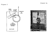
- the two ring specimens are marked with an indelible marker at quarterly points around the circumference beginning at TDC (if known, as shown in figure 1.
- test piece in the jig as shown in Figures 2 and 2a.
- the skin is then peeled from the pipe at a separation rate of 100mm/min and a trace recorded of load versus time.
- the average value of the load required to peel the skin sample is calculated (Newtons), and divided by the true width of the peel sample to obtain the test result (Newtons/millimetre) .
- the average of the 10 peak load values recorded is calculated (Newtons), and divided by the true width of the peel sample to obtain the test result (Newtons/millimetre).
Landscapes
- Engineering & Computer Science (AREA)
- General Engineering & Computer Science (AREA)
- Mechanical Engineering (AREA)
- Laminated Bodies (AREA)
- Extrusion Moulding Of Plastics Or The Like (AREA)
- Rigid Pipes And Flexible Pipes (AREA)
- Protection Of Pipes Against Damage, Friction, And Corrosion (AREA)
Claims (17)
- Kunststoffrohr mit einem Innenteil und einer damit verbondeten entfernbaren Außenhautschicht, wobei die entfernbare Außenhautschicht mindestens zwei Schichten aus kompatiblen Polymermaterialien umfasst, nämlich eine erste äußere Schutzschicht, die aufgrund ihrer physikalischen und mechanischen Eigenschaften gewählt ist, und eine zweite innere Verbondungsschicht, die an dem Innenteil haftet, wobei die Haftung der Verbondungsschicht an dem inneren Kern ausreicht, um im wesentlichen unerwünschte Relativbewegungen zwischen der Hautschicht und dem Innenteil während der Installation zu verhindern, jedoch nicht ausreicht, um, zumindest an den Enden des Rohres, ein sauberes Entfernen der Außenhautschicht durch Abziehen zu verhindern, und nicht ausreicht, um eine wesentliche Verringerung der Stoßfestigkeit des Innenteils zu bewirken, dadurch gekennzeichnet, dass die Festigkeit der Haftverbindung zwischen der ersten äußeren Schutzschicht und der zweiten inneren Verbondungsschicht der Hautschicht zumindest das Doppelte der Festigkeit der Haftverbindung zwischen der Verbondungsschicht und dem Innenteil beträgt.
- Kunststoffrohr nach Anspruch 1, bei dem die Festigkeit der Haftverbindung zwischen der ersten äußeren Schutzschicht und der zweiten inneren Verbondungsschicht der Hautschicht mindestens das Fünffache der Festigkeit der Haftverbindung zwischen der Verbondungsschicht und dem Innenteil beträgt.
- Kunststoffrohr nach Anspruch 1 oder 2, bei dem die Haftung zwischen der inneren Verbondungsschicht und dem Innenteil, gemessen durch einen im Anhang 1 beschriebenen Drehtrommel-Schälversuch, zwischen 0,3 und 1,5 N/mm beträgt.
- Kunststoffrohr nach einem der vorhergehenden Ansprüche, wobei die Festigkeit der Haftverbindung zwischen der Hautschicht und dem inneren Kern derart ist, dass die Stoßfestigkeit des Verbundrohres mindestens 75% der Stoßfestigkeit des Innenteils ohne die Hautschicht beträgt.
- Kunststoffrohr nach einem der vorhergehenden Ansprüche, bei dem das Innenteil Polyethylen aufweist.
- Kunststoffrohr nach einem der vorhergehenden Ansprüche, bei dem die äußere Schutzschicht ein Propylen-Homo- oder -Copolymer oder ein Propylen-Block-Copolymer aufweist.
- Kunststoffrohr nach einem der vorhergehenden Ansprüche, bei dem die zweite innere Verbondungsschicht ein Propylen-Homo- oder -Copolymer oder ein Propylen-Block-Copolymer aufweist.
- Kunststoffrohr nach Anspruch 7, bei dem die innere Verbondungsschicht ein Propylen-Random-Copolymer aufweist.
- Kunststoffrohr nach einem der vorhergehenden Ansprüche, mit einem Innenteil aus Polyethylen und einer Haut, welche eine äußere Schicht aus einem Propylen-Block-Copolymer und eine innere Schicht aus einem Propylen-Random-Copolymer aufweist.
- Kunststoffrohr nach einem der vorhergehenden Ansprüche, bei dem das Innenteil Polyethylen aufweist und die Hautschicht ein Propylen-Copolymer aufweist, und bei dem die Stoßfestigkeit des Rohres höher als 300 Joules ist, gemessen nach dem Verfahren gemäß EN1411:1996 bei einer Temperatur von -10°C unter Verwendung eines 90mm-Stoßkörpers zum Aufbringen eines Stoßes auf das Rohr.
- Kunststoffrohr nach einem der vorhergehenden Ansprüche, bei dem die Hautschicht eine Dicke in dem Bereich von 0,3 mm bis 2,0 mm aufweist.
- Kunststoffrohr nach einem der vorhergehenden Ansprüche, bei dem die erste äußere Schutzschicht eine Dicke zwischen 0,3 mm und 1,8 mm aufweist.
- Kunststoffrohr nach einem der vorhergehenden Ansprüche, bei dem die zweite innere Verbondungsschicht eine Dicke zwischen 0,025 mm und 0,2 mm aufweist.
- Kunststoffrohr nach einem der vorhergehenden Ansprüche, bei dem das Verhältnis zwischen dem Außendurchmesser des Rohres und der Dicke der Hautschicht zwischen 150 und 800 beträgt.
- Verfahren zur Herstellung eines Kunststoffrohres mit einem Innenteil und einer damit verbondeten entfernbaren Außenhautschicht, wobei die entfernbare Außenhautschicht mindestens zwei Schichten aus kompatiblen Polymermaterialien aufweist, nämlich eine erste äußere Schutzschicht, die aufgrund ihrer physikalischen und mechanischen Eigenschaften gewählt ist, und eine zweite innere Verbondungsschicht, die an dem Innenteil haftet, wobei das Verfahren umfasst: das Coextrudieren geschmolzener Polymermaterialien, welche das Innenteil und die entfernbare Außenhautschicht bilden, aus einer oder mehr Extruderdüsen, Zusammenbringen der geschmolzenen Kunststoffmaterialien und Abkühlenlassen derselben, so dass beim Abkühlen die Haftung der Verbondungsschicht an dem Innenteil ausreicht, wesentliche unerwünschte Relativbewegungen zwischen der Hautschicht und dem Innenteil während des Installierens des Rohres zu verhindern, jedoch nicht ausreicht, um zumindest an den Enden des Rohres ein sauberes Entfernen der Außenhautschicht durch Abziehen zu verhindern, und nicht ausreicht, um eine wesentliche Verringerung der Stoßfestigkeit des Innenteils zu bewirken, dadurch gekennzeichnet, dass die Festigkeit der Haftverbindung zwischen der ersten äußeren Schutzschicht und der zweiten inneren Verbondungsschicht der Hautschicht zumindest das Doppelte der Festigkeit der Haftverbindung zwischen der Verbondungsschicht und dem Innenteil beträgt.
- Verfahren nach Anspruch 15, bei dem die Polymermaterialien des Innenteils und der entfernbaren Außenhautschicht gleichzeitig extrudiert werden und noch im warmen Zustand zusammengebracht werden.
- Verfahren zur Herstellung einer Verbindung mit einem Kunststoffrohr nach einem der Ansprüche 1 bis 14, oder zum Verbinden zweier derartiger Kunststoffrohre, umfassend das Abziehen der Hautschicht von dem zu verbindenden Bereich oder den zu verbindenden Bereichen des Rohres, um eine saubere Fläche freizulegen, die für ein Verbinden durch E-lektroschmelzen geeignet ist, Anbringen eines Elektroschmelzfittings über der sauberen Fläche oder den sauberen Flächen des Rohres oder der Rohre, und Aktivieren des Elektroschmelzfittings zum Schmelzen des Bereichs oder der Bereiche des Rohres oder der Rohre mit diesem.
Applications Claiming Priority (3)
| Application Number | Priority Date | Filing Date | Title |
|---|---|---|---|
| GB0219273 | 2002-08-19 | ||
| GB0219273A GB2392220B (en) | 2002-08-19 | 2002-08-19 | Plastics pipe |
| PCT/GB2003/003617 WO2004016976A1 (en) | 2002-08-19 | 2003-08-19 | Plastics pipe |
Publications (2)
| Publication Number | Publication Date |
|---|---|
| EP1540222A1 EP1540222A1 (de) | 2005-06-15 |
| EP1540222B1 true EP1540222B1 (de) | 2007-04-25 |
Family
ID=9942570
Family Applications (1)
| Application Number | Title | Priority Date | Filing Date |
|---|---|---|---|
| EP03787918A Expired - Lifetime EP1540222B1 (de) | 2002-08-19 | 2003-08-19 | Kunststoffrohr |
Country Status (10)
| Country | Link |
|---|---|
| US (1) | US20060124191A1 (de) |
| EP (1) | EP1540222B1 (de) |
| AT (1) | ATE360777T1 (de) |
| AU (1) | AU2003255806B2 (de) |
| DE (1) | DE60313476T2 (de) |
| DK (1) | DK1540222T3 (de) |
| ES (1) | ES2282715T3 (de) |
| GB (1) | GB2392220B (de) |
| PT (1) | PT1540222E (de) |
| WO (1) | WO2004016976A1 (de) |
Families Citing this family (8)
| Publication number | Priority date | Publication date | Assignee | Title |
|---|---|---|---|---|
| GB2421469B (en) | 2004-12-23 | 2010-03-03 | Uponor Innovation Ab | Plastic pipe |
| GB2437540B (en) | 2006-04-24 | 2010-12-01 | Uponor Innovation Ab | Fastening of pipes |
| CN102287588A (zh) * | 2011-07-19 | 2011-12-21 | 云南聚博橡胶工程有限公司 | 环保型柔性减阻双层复合矿浆输送管道及其制备方法 |
| EP2716439A1 (de) | 2012-10-04 | 2014-04-09 | egeplast international GmbH | Gegenstand mit mehrschichtiger Außenseite |
| EP2951511A1 (de) * | 2013-02-01 | 2015-12-09 | Muovitech AB | Geothermisches kollektorrohr |
| NL1041400B1 (en) | 2015-07-14 | 2017-01-30 | Wavin Bv | Multilayered pipe and method of manufacturing the same. |
| EP3463858B1 (de) * | 2016-06-01 | 2021-10-20 | Wavin B.V. | Mehrschichtiges rohr und verfahren zur formung eines mehrschichtigen rohrs |
| NL1042164B1 (en) | 2016-11-29 | 2018-06-18 | Wavin Bv | A multi-layered pipe and a method for forming a multi-layered pipe |
Family Cites Families (17)
| Publication number | Priority date | Publication date | Assignee | Title |
|---|---|---|---|---|
| DE3312058A1 (de) * | 1982-11-16 | 1984-05-17 | Ercos-Therma Wärmetechnik GmbH & Co KG, 4000 Düsseldorf | Rohr fuer fussbodenheizung |
| US4606953A (en) * | 1983-06-23 | 1986-08-19 | Nippon Steel Corporation | Polypropylene coated steel pipe |
| US4559095A (en) * | 1984-06-07 | 1985-12-17 | The B. F. Goodrich Company | Vulcanization of hose composites protected with thermoplastic jackets |
| GB2171484B (en) * | 1985-02-21 | 1989-11-29 | Ashimori Ind Co Ltd | A tubular lining material |
| FI99158C (fi) * | 1991-06-28 | 1997-10-10 | Uponor Bv | Menetelmä muoviputken pinnan suojaamiseksi sähköhitsaamalla tapahtuvaa liittämistä varten ja sähköhitsattava muoviputki |
| JP3157046B2 (ja) * | 1992-08-06 | 2001-04-16 | 昭和電工株式会社 | 積層体 |
| US5489473A (en) * | 1994-04-07 | 1996-02-06 | Borden, Inc. | Biaxially and monoaxially oriented polypropylene cold seal release film |
| DE59507273D1 (de) * | 1994-07-13 | 1999-12-30 | Hoechst Trespaphan Gmbh | Peelfähige, siegelbare polyolefinische Mehrschichtfolie |
| GB2297137B (en) * | 1995-01-18 | 1999-02-03 | Uponor Ltd | Plastics pipe |
| DE19548789A1 (de) * | 1995-12-27 | 1997-07-03 | Hoechst Trespaphan Gmbh | Peelfähige, siegelbare polyolefinische Mehrschichtfolie, Verfahren zu ihrer Herstellung und ihre Verwendung |
| JP4345995B2 (ja) * | 1997-05-20 | 2009-10-14 | 臼井国際産業株式会社 | 重合被覆金属管 |
| US6976510B2 (en) * | 2000-01-19 | 2005-12-20 | Itt Manufacturing Enterprises, Inc. | Corrosion resistant metal tube and process for making the same |
| US6866928B2 (en) * | 2002-04-08 | 2005-03-15 | 3M Innovative Properties Company | Cleanly removable tapes and methods for the manufacture thereof |
| US6770361B2 (en) * | 2002-12-13 | 2004-08-03 | Exxonmobil Oil Corporation | Sealable and peelable film structure |
| US6896956B2 (en) * | 2002-12-13 | 2005-05-24 | Exxonmobil Oil Corporation | Sealable and peelable film structure |
| JP2008517802A (ja) * | 2004-10-22 | 2008-05-29 | ダウ グローバル テクノロジーズ インコーポレイティド | 改善されたミクロ層構造及び方法 |
| JP2006288887A (ja) * | 2005-04-13 | 2006-10-26 | Nitto Denko Corp | 貼付製剤 |
-
2002
- 2002-08-19 GB GB0219273A patent/GB2392220B/en not_active Expired - Fee Related
-
2003
- 2003-08-19 EP EP03787918A patent/EP1540222B1/de not_active Expired - Lifetime
- 2003-08-19 DK DK03787918T patent/DK1540222T3/da active
- 2003-08-19 US US10/525,183 patent/US20060124191A1/en not_active Abandoned
- 2003-08-19 DE DE60313476T patent/DE60313476T2/de not_active Expired - Lifetime
- 2003-08-19 AT AT03787918T patent/ATE360777T1/de active
- 2003-08-19 ES ES03787918T patent/ES2282715T3/es not_active Expired - Lifetime
- 2003-08-19 WO PCT/GB2003/003617 patent/WO2004016976A1/en not_active Ceased
- 2003-08-19 AU AU2003255806A patent/AU2003255806B2/en not_active Ceased
- 2003-08-19 PT PT03787918T patent/PT1540222E/pt unknown
Also Published As
| Publication number | Publication date |
|---|---|
| GB2392220B (en) | 2005-10-26 |
| PT1540222E (pt) | 2007-05-31 |
| US20060124191A1 (en) | 2006-06-15 |
| DE60313476D1 (de) | 2007-06-06 |
| GB2392220A (en) | 2004-02-25 |
| DE60313476T2 (de) | 2008-01-03 |
| WO2004016976A1 (en) | 2004-02-26 |
| GB0219273D0 (en) | 2002-09-25 |
| AU2003255806B2 (en) | 2007-11-08 |
| ES2282715T3 (es) | 2007-10-16 |
| ATE360777T1 (de) | 2007-05-15 |
| EP1540222A1 (de) | 2005-06-15 |
| AU2003255806A1 (en) | 2004-03-03 |
| DK1540222T3 (da) | 2007-09-03 |
Similar Documents
| Publication | Publication Date | Title |
|---|---|---|
| EP0804699B1 (de) | Kunststoffrohr | |
| EP1540222B1 (de) | Kunststoffrohr | |
| US20060169343A1 (en) | Plastics pipe | |
| EP3548276A1 (de) | Mehrschichtiges rohr und verwendung eines mehrschichtigen rohrs | |
| AU2003269094B2 (en) | Plastics pipe | |
| US8398908B2 (en) | Plastics pipe | |
| EP1877244B1 (de) | Kunststoffrohr | |
| AU749342B2 (en) | Plastics pipe |
Legal Events
| Date | Code | Title | Description |
|---|---|---|---|
| PUAI | Public reference made under article 153(3) epc to a published international application that has entered the european phase |
Free format text: ORIGINAL CODE: 0009012 |
|
| 17P | Request for examination filed |
Effective date: 20050216 |
|
| AK | Designated contracting states |
Kind code of ref document: A1 Designated state(s): AT BE BG CH CY CZ DE DK EE ES FI FR GB GR HU IE IT LI LU MC NL PT RO SE SI SK TR |
|
| AX | Request for extension of the european patent |
Extension state: AL LT LV MK |
|
| DAX | Request for extension of the european patent (deleted) | ||
| GRAP | Despatch of communication of intention to grant a patent |
Free format text: ORIGINAL CODE: EPIDOSNIGR1 |
|
| GRAS | Grant fee paid |
Free format text: ORIGINAL CODE: EPIDOSNIGR3 |
|
| GRAA | (expected) grant |
Free format text: ORIGINAL CODE: 0009210 |
|
| AK | Designated contracting states |
Kind code of ref document: B1 Designated state(s): AT BE BG CH CY CZ DE DK EE ES FI FR GB GR HU IE IT LI LU MC NL PT RO SE SI SK TR |
|
| PG25 | Lapsed in a contracting state [announced via postgrant information from national office to epo] |
Ref country code: FI Free format text: LAPSE BECAUSE OF FAILURE TO SUBMIT A TRANSLATION OF THE DESCRIPTION OR TO PAY THE FEE WITHIN THE PRESCRIBED TIME-LIMIT Effective date: 20070425 |
|
| RBV | Designated contracting states (corrected) |
Designated state(s): AT BE BG CH CY CZ DE DK EE ES FI FR GB GR HU IE IT LI LU MC NL PT RO SE SI SK TR |
|
| REG | Reference to a national code |
Ref country code: GB Ref legal event code: FG4D |
|
| REG | Reference to a national code |
Ref country code: IE Ref legal event code: FG4D |
|
| REG | Reference to a national code |
Ref country code: PT Ref legal event code: SC4A Free format text: AVAILABILITY OF NATIONAL TRANSLATION Effective date: 20070514 Ref country code: CH Ref legal event code: EP |
|
| REF | Corresponds to: |
Ref document number: 60313476 Country of ref document: DE Date of ref document: 20070606 Kind code of ref document: P |
|
| REG | Reference to a national code |
Ref country code: CH Ref legal event code: NV Representative=s name: TROESCH SCHEIDEGGER WERNER AG |
|
| REG | Reference to a national code |
Ref country code: SE Ref legal event code: TRGR |
|
| REG | Reference to a national code |
Ref country code: GR Ref legal event code: EP Ref document number: 20070401992 Country of ref document: GR |
|
| REG | Reference to a national code |
Ref country code: DK Ref legal event code: T3 |
|
| ET | Fr: translation filed | ||
| REG | Reference to a national code |
Ref country code: ES Ref legal event code: FG2A Ref document number: 2282715 Country of ref document: ES Kind code of ref document: T3 |
|
| PG25 | Lapsed in a contracting state [announced via postgrant information from national office to epo] |
Ref country code: SI Free format text: LAPSE BECAUSE OF FAILURE TO SUBMIT A TRANSLATION OF THE DESCRIPTION OR TO PAY THE FEE WITHIN THE PRESCRIBED TIME-LIMIT Effective date: 20070425 Ref country code: CZ Free format text: LAPSE BECAUSE OF FAILURE TO SUBMIT A TRANSLATION OF THE DESCRIPTION OR TO PAY THE FEE WITHIN THE PRESCRIBED TIME-LIMIT Effective date: 20070425 Ref country code: BG Free format text: LAPSE BECAUSE OF FAILURE TO SUBMIT A TRANSLATION OF THE DESCRIPTION OR TO PAY THE FEE WITHIN THE PRESCRIBED TIME-LIMIT Effective date: 20070725 |
|
| PLBI | Opposition filed |
Free format text: ORIGINAL CODE: 0009260 |
|
| PLAX | Notice of opposition and request to file observation + time limit sent |
Free format text: ORIGINAL CODE: EPIDOSNOBS2 |
|
| PG25 | Lapsed in a contracting state [announced via postgrant information from national office to epo] |
Ref country code: SK Free format text: LAPSE BECAUSE OF FAILURE TO SUBMIT A TRANSLATION OF THE DESCRIPTION OR TO PAY THE FEE WITHIN THE PRESCRIBED TIME-LIMIT Effective date: 20070425 |
|
| 26 | Opposition filed |
Opponent name: WAVIN B.V. Effective date: 20080125 |
|
| PG25 | Lapsed in a contracting state [announced via postgrant information from national office to epo] |
Ref country code: MC Free format text: LAPSE BECAUSE OF NON-PAYMENT OF DUE FEES Effective date: 20070831 |
|
| NLR1 | Nl: opposition has been filed with the epo |
Opponent name: WAVIN B.V. |
|
| PG25 | Lapsed in a contracting state [announced via postgrant information from national office to epo] |
Ref country code: RO Free format text: LAPSE BECAUSE OF FAILURE TO SUBMIT A TRANSLATION OF THE DESCRIPTION OR TO PAY THE FEE WITHIN THE PRESCRIBED TIME-LIMIT Effective date: 20070425 |
|
| PLBP | Opposition withdrawn |
Free format text: ORIGINAL CODE: 0009264 |
|
| PLAF | Information modified related to communication of a notice of opposition and request to file observations + time limit |
Free format text: ORIGINAL CODE: EPIDOSCOBS2 |
|
| PLBB | Reply of patent proprietor to notice(s) of opposition received |
Free format text: ORIGINAL CODE: EPIDOSNOBS3 |
|
| REG | Reference to a national code |
Ref country code: GB Ref legal event code: 732E |
|
| REG | Reference to a national code |
Ref country code: CH Ref legal event code: PUE Owner name: RADIUS SYSTEMS LIMITED Free format text: UPONOR INNOVATION AB#INDUSTRIVAEGEN#513 81 FRISTAD (SE) -TRANSFER TO- RADIUS SYSTEMS LIMITED#HILCOTE PLANT PO BOX 1#BLACKWELL, NR ALFRETON, DERBYSHIRE DE 55 5JD (GB) |
|
| PG25 | Lapsed in a contracting state [announced via postgrant information from national office to epo] |
Ref country code: EE Free format text: LAPSE BECAUSE OF FAILURE TO SUBMIT A TRANSLATION OF THE DESCRIPTION OR TO PAY THE FEE WITHIN THE PRESCRIBED TIME-LIMIT Effective date: 20070425 |
|
| BECN | Be: change of holder's name |
Owner name: RADIUS SYSTEMS LTD Effective date: 20090211 |
|
| REG | Reference to a national code |
Ref country code: FR Ref legal event code: TP Ref country code: FR Ref legal event code: CD |
|
| PLBD | Termination of opposition procedure: decision despatched |
Free format text: ORIGINAL CODE: EPIDOSNOPC1 |
|
| PG25 | Lapsed in a contracting state [announced via postgrant information from national office to epo] |
Ref country code: CY Free format text: LAPSE BECAUSE OF FAILURE TO SUBMIT A TRANSLATION OF THE DESCRIPTION OR TO PAY THE FEE WITHIN THE PRESCRIBED TIME-LIMIT Effective date: 20070425 |
|
| PG25 | Lapsed in a contracting state [announced via postgrant information from national office to epo] |
Ref country code: LU Free format text: LAPSE BECAUSE OF NON-PAYMENT OF DUE FEES Effective date: 20070819 |
|
| PLBM | Termination of opposition procedure: date of legal effect published |
Free format text: ORIGINAL CODE: 0009276 |
|
| STAA | Information on the status of an ep patent application or granted ep patent |
Free format text: STATUS: OPPOSITION PROCEDURE CLOSED |
|
| PG25 | Lapsed in a contracting state [announced via postgrant information from national office to epo] |
Ref country code: HU Free format text: LAPSE BECAUSE OF FAILURE TO SUBMIT A TRANSLATION OF THE DESCRIPTION OR TO PAY THE FEE WITHIN THE PRESCRIBED TIME-LIMIT Effective date: 20071026 Ref country code: TR Free format text: LAPSE BECAUSE OF FAILURE TO SUBMIT A TRANSLATION OF THE DESCRIPTION OR TO PAY THE FEE WITHIN THE PRESCRIBED TIME-LIMIT Effective date: 20070425 |
|
| 27C | Opposition proceedings terminated |
Effective date: 20090606 |
|
| REG | Reference to a national code |
Ref country code: PT Ref legal event code: PC4A Owner name: UPONOR LIMITED, GB Effective date: 20091028 |
|
| NLR2 | Nl: decision of opposition |
Effective date: 20090606 |
|
| NLS | Nl: assignments of ep-patents |
Owner name: UPONOR LIMITED Effective date: 20091014 |
|
| NLT1 | Nl: modifications of names registered in virtue of documents presented to the patent office pursuant to art. 16 a, paragraph 1 |
Owner name: RADIUS SYSTEMS LIMITED |
|
| PG25 | Lapsed in a contracting state [announced via postgrant information from national office to epo] |
Ref country code: IT Free format text: LAPSE BECAUSE OF NON-PAYMENT OF DUE FEES Effective date: 20090819 |
|
| PGRI | Patent reinstated in contracting state [announced from national office to epo] |
Ref country code: IT Effective date: 20110616 |
|
| PGFP | Annual fee paid to national office [announced via postgrant information from national office to epo] |
Ref country code: CH Payment date: 20110824 Year of fee payment: 9 |
|
| PGFP | Annual fee paid to national office [announced via postgrant information from national office to epo] |
Ref country code: ES Payment date: 20110812 Year of fee payment: 9 Ref country code: FR Payment date: 20110901 Year of fee payment: 9 Ref country code: PT Payment date: 20110818 Year of fee payment: 9 Ref country code: GR Payment date: 20110822 Year of fee payment: 9 Ref country code: AT Payment date: 20110812 Year of fee payment: 9 |
|
| PGFP | Annual fee paid to national office [announced via postgrant information from national office to epo] |
Ref country code: IT Payment date: 20110825 Year of fee payment: 9 Ref country code: BE Payment date: 20110811 Year of fee payment: 9 Ref country code: NL Payment date: 20110825 Year of fee payment: 9 |
|
| REG | Reference to a national code |
Ref country code: PT Ref legal event code: MM4A Free format text: LAPSE DUE TO NON-PAYMENT OF FEES Effective date: 20130219 |
|
| BERE | Be: lapsed |
Owner name: RADIUS SYSTEMS LTD Effective date: 20120831 |
|
| REG | Reference to a national code |
Ref country code: NL Ref legal event code: V1 Effective date: 20130301 |
|
| REG | Reference to a national code |
Ref country code: CH Ref legal event code: PL |
|
| REG | Reference to a national code |
Ref country code: AT Ref legal event code: MM01 Ref document number: 360777 Country of ref document: AT Kind code of ref document: T Effective date: 20120819 |
|
| PG25 | Lapsed in a contracting state [announced via postgrant information from national office to epo] |
Ref country code: NL Free format text: LAPSE BECAUSE OF NON-PAYMENT OF DUE FEES Effective date: 20130301 Ref country code: LI Free format text: LAPSE BECAUSE OF NON-PAYMENT OF DUE FEES Effective date: 20120831 Ref country code: CH Free format text: LAPSE BECAUSE OF NON-PAYMENT OF DUE FEES Effective date: 20120831 |
|
| REG | Reference to a national code |
Ref country code: GR Ref legal event code: ML Ref document number: 20070401992 Country of ref document: GR Effective date: 20130304 |
|
| REG | Reference to a national code |
Ref country code: FR Ref legal event code: ST Effective date: 20130430 |
|
| PG25 | Lapsed in a contracting state [announced via postgrant information from national office to epo] |
Ref country code: IT Free format text: LAPSE BECAUSE OF NON-PAYMENT OF DUE FEES Effective date: 20120819 Ref country code: GR Free format text: LAPSE BECAUSE OF NON-PAYMENT OF DUE FEES Effective date: 20130304 Ref country code: BE Free format text: LAPSE BECAUSE OF NON-PAYMENT OF DUE FEES Effective date: 20120831 Ref country code: PT Free format text: LAPSE BECAUSE OF NON-PAYMENT OF DUE FEES Effective date: 20130219 |
|
| PG25 | Lapsed in a contracting state [announced via postgrant information from national office to epo] |
Ref country code: AT Free format text: LAPSE BECAUSE OF NON-PAYMENT OF DUE FEES Effective date: 20120819 |
|
| PG25 | Lapsed in a contracting state [announced via postgrant information from national office to epo] |
Ref country code: FR Free format text: LAPSE BECAUSE OF NON-PAYMENT OF DUE FEES Effective date: 20120831 |
|
| REG | Reference to a national code |
Ref country code: ES Ref legal event code: FD2A Effective date: 20131023 |
|
| PGFP | Annual fee paid to national office [announced via postgrant information from national office to epo] |
Ref country code: DK Payment date: 20130821 Year of fee payment: 11 Ref country code: SE Payment date: 20130821 Year of fee payment: 11 |
|
| PG25 | Lapsed in a contracting state [announced via postgrant information from national office to epo] |
Ref country code: ES Free format text: LAPSE BECAUSE OF NON-PAYMENT OF DUE FEES Effective date: 20120820 |
|
| REG | Reference to a national code |
Ref country code: DK Ref legal event code: EBP Effective date: 20140831 |
|
| REG | Reference to a national code |
Ref country code: SE Ref legal event code: EUG |
|
| PG25 | Lapsed in a contracting state [announced via postgrant information from national office to epo] |
Ref country code: SE Free format text: LAPSE BECAUSE OF NON-PAYMENT OF DUE FEES Effective date: 20140820 |
|
| PG25 | Lapsed in a contracting state [announced via postgrant information from national office to epo] |
Ref country code: DK Free format text: LAPSE BECAUSE OF NON-PAYMENT OF DUE FEES Effective date: 20140831 |
|
| PGFP | Annual fee paid to national office [announced via postgrant information from national office to epo] |
Ref country code: DE Payment date: 20170822 Year of fee payment: 15 Ref country code: GB Payment date: 20170822 Year of fee payment: 15 |
|
| PGFP | Annual fee paid to national office [announced via postgrant information from national office to epo] |
Ref country code: IE Payment date: 20170825 Year of fee payment: 15 |
|
| REG | Reference to a national code |
Ref country code: DE Ref legal event code: R119 Ref document number: 60313476 Country of ref document: DE |
|
| GBPC | Gb: european patent ceased through non-payment of renewal fee |
Effective date: 20180819 |
|
| REG | Reference to a national code |
Ref country code: IE Ref legal event code: MM4A |
|
| PG25 | Lapsed in a contracting state [announced via postgrant information from national office to epo] |
Ref country code: IE Free format text: LAPSE BECAUSE OF NON-PAYMENT OF DUE FEES Effective date: 20180819 Ref country code: DE Free format text: LAPSE BECAUSE OF NON-PAYMENT OF DUE FEES Effective date: 20190301 |
|
| PG25 | Lapsed in a contracting state [announced via postgrant information from national office to epo] |
Ref country code: GB Free format text: LAPSE BECAUSE OF NON-PAYMENT OF DUE FEES Effective date: 20180819 |