EP1539413B9 - Cutting insert and method - Google Patents
Cutting insert and method Download PDFInfo
- Publication number
- EP1539413B9 EP1539413B9 EP03733802A EP03733802A EP1539413B9 EP 1539413 B9 EP1539413 B9 EP 1539413B9 EP 03733802 A EP03733802 A EP 03733802A EP 03733802 A EP03733802 A EP 03733802A EP 1539413 B9 EP1539413 B9 EP 1539413B9
- Authority
- EP
- European Patent Office
- Prior art keywords
- cutting
- edge
- cutting insert
- corner
- nose
- Prior art date
- Legal status (The legal status is an assumption and is not a legal conclusion. Google has not performed a legal analysis and makes no representation as to the accuracy of the status listed.)
- Expired - Lifetime
Links
Images


Classifications
-
- B—PERFORMING OPERATIONS; TRANSPORTING
- B23—MACHINE TOOLS; METAL-WORKING NOT OTHERWISE PROVIDED FOR
- B23B—TURNING; BORING
- B23B27/00—Tools for turning or boring machines; Tools of a similar kind in general; Accessories therefor
- B23B27/14—Cutting tools of which the bits or tips or cutting inserts are of special material
- B23B27/141—Specially shaped plate-like cutting inserts, i.e. length greater or equal to width, width greater than or equal to thickness
- B23B27/145—Specially shaped plate-like cutting inserts, i.e. length greater or equal to width, width greater than or equal to thickness characterised by having a special shape
-
- B—PERFORMING OPERATIONS; TRANSPORTING
- B23—MACHINE TOOLS; METAL-WORKING NOT OTHERWISE PROVIDED FOR
- B23B—TURNING; BORING
- B23B2200/00—Details of cutting inserts
- B23B2200/12—Side or flank surfaces
- B23B2200/125—Side or flank surfaces discontinuous
-
- B—PERFORMING OPERATIONS; TRANSPORTING
- B23—MACHINE TOOLS; METAL-WORKING NOT OTHERWISE PROVIDED FOR
- B23B—TURNING; BORING
- B23B2200/00—Details of cutting inserts
- B23B2200/20—Top or side views of the cutting edge
- B23B2200/201—Details of the nose radius and immediately surrounding area
-
- Y—GENERAL TAGGING OF NEW TECHNOLOGICAL DEVELOPMENTS; GENERAL TAGGING OF CROSS-SECTIONAL TECHNOLOGIES SPANNING OVER SEVERAL SECTIONS OF THE IPC; TECHNICAL SUBJECTS COVERED BY FORMER USPC CROSS-REFERENCE ART COLLECTIONS [XRACs] AND DIGESTS
- Y10—TECHNICAL SUBJECTS COVERED BY FORMER USPC
- Y10T—TECHNICAL SUBJECTS COVERED BY FORMER US CLASSIFICATION
- Y10T407/00—Cutters, for shaping
- Y10T407/23—Cutters, for shaping including tool having plural alternatively usable cutting edges
- Y10T407/235—Cutters, for shaping including tool having plural alternatively usable cutting edges with integral chip breaker, guide or deflector
Definitions
- the present invention relates to a cutting insert for chip removing machining according to the preamble of the appended independent claim 1.
- indexable, asymmetrical inserts of hard and wear-resistant materials are used, such as cemented carbide or cubic boron nitride (CBN).
- CBN cubic boron nitride
- cutting inserts for use in only one feeding direction are usually denominated right or left hand inserts and comprise peripheries and/or chip breakers having an asymmetrical shape in relation to the bisector of a cutting corner. These cutting inserts are adapted for only one feeding direction.
- indexable inserts having asymmetrical cutting corners are shown in US-A-3 955 259 , SE 517274 ( WO 0047405 ), GB 1443743 and US-A-3 229 349 .
- One object of the present invention is to provide a cutting insert that avoids the above-mentioned drawbacks.
- Another object of the present invention is to provide an indexable cutting insert that only is of left or right hand design.
- Another additional object of the present invention is to provide a cutting insert, which can utilize both sides of the cutting insert.
- Fig. 1A shows a planar view of a triangular indexable insert according to the present invention
- Fig. 1B shows a cross-section of the indexable insert according to the line. IB-IB in Fig. 1A
- Fig. 1C shows a cross-section of the indexable insert according to the line IC-IC in Fig. 1A
- Fig. 1D shows a cross-section of the indexable insert according to the line ID-ID in Fig. 1A
- Fig. 1E shows an enlargement of a cutting corner in Fig. 1A
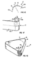
- Fig. 1F shows the cutting corner in perspective view
- FIG. 1G shows the indexable insert in perspective view
- Fig. 2A shows the indexable insert at longitudinal turning in a workpiece
- Fig. 2B shows the indexable insert at transverse turning in a workpiece
- Fig. 2C shows the indexable insert at copying a workpiece on a lathe
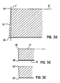
- Fig. 3A shows a planar view of a rhombic indexable insert according to the present invention
- Fig. 3B shows an enlargement of a cutting corner in Fig. 3A in perspective view
- Fig. 3C shows a cross-section of the indexable insert according to the line IIIC-IIIC in Fig. 3A
- Fig. 3D shows a cross-section of the indexable insert according to the line IC-IC in Fig. 1A
- Fig. 3E shows a cross-section of the indexable insert according to the line IIIE-IIIE in Fig. 1A .
- the indexable insert 10 in Figs. 1A-1G is intended for turning or milling.
- the cutting insert which is shown in right hand design, has a substantially triangular basic shape and comprises a top side 11, a bottom side 12, and three edge surfaces 13, which substantially connects the top and bottom sides 11 and 12, respectively.
- the cutting insert 10 has a negative geometry, i.e. each edge surface 13 is perpendicular to a plane P, which coincides with the top side 11 or the bottom side 12, which means that the cutting insert has a substantially constant clearance angle around the cutting insert, also in the cutting corners.
- the cutting insert consists of sintered cemented carbide (for instance WC + Co) or cubic boron nitride (CBN) or a combination of CBN and cemented carbide where the cutting corners consist of CBN plates.
- the top side 11 constitutes rake face and the edge surface 13 constitutes edge surface.
- Upper major cutting edges 15A are formed at transitions between the top side 11 and the edge surfaces 13 of the cutting insert.
- Lower cutting edges 16A are formed at transitions between the bottom side 12 and the edge surfaces 13.
- Said sides 11, 12 constitute a rake face in a position when the side 11 is active in chip forming machining and a support surface when the cutting insert has been turned upside down.
- Each side 11, 12 comprises a planar surface, the periphery of which may be provided with an edge strengthening chamfer 14.
- the cutting insert 10 has three cutting corners 17. Each cutting corner 17 comprises a nose edge 18 and a minor cutting edge 19.
- the nose edge 18 connects to the connected major cutting edge 15A and to the connected minor cutting edge 19.
- the cutting corner 17 has a bisector B dividing the corner into equal parts (30 degrees each, in this case) in relation to the major cutting edges 15A, 15B.
- the bisector B intersects the nose edge 18, at both the top and the bottom sides 11, 12.
- Each cutting corner 17 is asymmetrical in relation to the bisector B in regards of the geometry of the edges 15A, 18, 19 and 15B.
- the nose edge 18 is curved and may be defined by a radius R1.
- the minor cutting edge 19 is curved and may be defined by a radius R2.
- the radius R1 is smaller than the radius R2 of the minor cutting edge.
- the minor cutting edge 19 connects to the non-associated major cutting edge 15B with a radius R3.
- the radius R3 is smaller than the radius R2 of the minor cutting edge but larger than the radius R1.
- Each side 11, 12 comprises three nose edges, which at least partly touch a plane P.
- the plane P is in this case parallel with both the top and the bottom sides.
- An imaginary line L which is perpendicular to the plane P and tangent to the minor cutting edge 19, intersects the edge surface 13 at a distance L1 from the minor cutting edge.
- the distance L1 equals about half of the thickness L2 of the cutting insert, Fig. 1C .
- the line L coincides with the edge surface 13 for about half of the thickness L2 of the cutting insert.
- the edge surface 13 has a step 20A, 20B on both sides of the bisector of the cutting corner.
- the step 20A, 20B is substantially parallel with the plane P.
- the step 20A, 20B forms a sharp corner 21 with the edge surface 13 next to the step 20A, 20B in order to constitute an indication of fracture that at a possible breaking of the cutting edge controls the breakage and keeps the lower part of the cutting insert intact.
- a direction oriented, double-sided wiper insert having only 3 radii in the cutting corner has the advantage that it is possible to form a radius or shoulder In a workpiece 30 to an exact geometry without the need for compensation in the NC program, i.e. the cutting insert leaves the workpiece having the same geometrical shape as a standard turning insert having a nose edge according to the ISO standard. This at the same time as the cutting insert has a wiper effect at longitudinal turning. i.e. the cutting insert leaves the workpiece having the same geometrical shape as a standard turning insert having a nose radius according to the standardized norm. Furthermore, a cutting insert formed in such a way provides lower radial cutting forces, which is desirable at generation of fine surfaces, than a traditional wiper insert having 5 radii after each other.
- the invention aims at getting away from this type of problem by forming only half of the thickness, and thereby obtaining a double-sided wiper insert that only is of left or right hand design.
- the step 20A, 20B protects the subjacent edge in an effective way. Since the cutting inserts are expensive, such as CBN inserts, the operator often machines too long. Without a wiper, this entails numerous measurement corrections in the turning lathe. The CBN insert maintains the measurements well, even after considerable wear. Finally, it breaks down.
- the indexable insert according to the present invention ensures that the cutting edge below is protected.
- Fig. 2A shows the indexable insert at longitudinal turning of the workpiece 30 with the feeding direction according to the arrow in Fig. 2A.
- Fig. 2B shows the indexable insert 10 at transverse turning of the workpiece 30, wherein the minor cutting edge substantially does not machine the same.
- Fig. 2C shows the indexable insert during copying of the workpiece 30 on a lathe.
- the cutting insert has been mounted in insert holders with a setting angle of 93°, and a clearance angle and minor insert angle of 6° each.
- the indexable insert 10 is manufactured in the following way.
- the edge surfaces are ground over the entire thickness in a conventional way.
- At least a first corner portion is machined, preferably by means of grinding, so that a first area, corresponding to approximately half the thickness, obtains a rounded nose edge 18 and a minor cutting edge 19. It is suitable to perform the corresponding machining on the other corner portions of the plate and then turn the polygonal plate upside down 180°.
- the plate is fastened in the fixture again in order to machine some of the corner portions, at least the first corner portion, preferably by means of grinding, so that a second area, corresponding to approximately half of the thickness, obtains a rounded nose edge 18 and a minor cutting edge 19. Then, it is advantageous to machine the nose edge 18 so that it obtains a radius R1 that is smaller than the radius R2 of the minor cutting edge. It is most suitable to grind all corner portions of one of the halves in one set-up.
- the indexable insert 10' in Figs. 3A-3E is intended for turning or milling.
- the cutting insert has a substantially rhombic basic shape with two cutting corners 17' and four cutting edge portions. Equally indexed reference numbers designate equal details mentioned above. What makes this cutting insert 10' different from the above-described cutting insert 10, in addition to the basic shape, is the shape of the edge surface 13' in the cutting corner 17'.
- This cutting insert 10' is injection-moulded or directly pressed and the edge surface 13' in the cutting corner has a continuous or stepless transition between the opposite cutting edges in a cutting corner.
- the cutting corner 17 has a nose edge 18' and a minor cutting edge 19'. The nose edge 18' connects to the associated major cutting edge 15A' and to the associated minor cutting edge 19'.
- the minor cutting edge 19' in turn connects to a non-associated major cutting edge 15B'.
- An imaginary line L' which is perpendicular to the plane P' and tangent to the minor cutting edge 19' intersects the edge surface 13' according to Fig. 3D .
- the edge surface 13' is concave.
- the cutting insert 10' has a through hole intended to receive a fixing screw (not shown), which fixes the cutting insert 10' to the insert holder.
- the present invention relates to an indexable, asymmetrical cutting insert, which is of only left or only right hand design that permits utilisation of both sides of the cutting insert for machining in the same direction.
- the cutting insert may have another polygonal basic shape, such as a square, rectangular, pentagonal, hexagonal or octagonal basic shape.
- the cutting insert 10 may be provided with a through hole intended to receive a fixing screw.
Landscapes
- Engineering & Computer Science (AREA)
- Mechanical Engineering (AREA)
- Cutting Tools, Boring Holders, And Turrets (AREA)
- Milling Processes (AREA)
Applications Claiming Priority (3)
| Application Number | Priority Date | Filing Date | Title |
|---|---|---|---|
| SE0201985A SE525829C2 (sv) | 2002-06-26 | 2002-06-26 | Dubbelsidigt vändskär med bomberad biskäregg samt tillverkningsmetod för skäret |
| SE0201985 | 2002-06-26 | ||
| PCT/SE2003/001104 WO2004002664A2 (en) | 2002-06-26 | 2003-06-24 | A double-sided indexable cutting insert with assymetric cutting corners |
Publications (3)
| Publication Number | Publication Date |
|---|---|
| EP1539413A2 EP1539413A2 (en) | 2005-06-15 |
| EP1539413B1 EP1539413B1 (en) | 2011-08-17 |
| EP1539413B9 true EP1539413B9 (en) | 2012-03-14 |
Family
ID=20288341
Family Applications (1)
| Application Number | Title | Priority Date | Filing Date |
|---|---|---|---|
| EP03733802A Expired - Lifetime EP1539413B9 (en) | 2002-06-26 | 2003-06-24 | Cutting insert and method |
Country Status (7)
| Country | Link |
|---|---|
| US (1) | US7118312B2 (sv) |
| EP (1) | EP1539413B9 (sv) |
| KR (2) | KR101087513B1 (sv) |
| CN (2) | CN1662335A (sv) |
| AT (1) | ATE520490T1 (sv) |
| SE (1) | SE525829C2 (sv) |
| WO (1) | WO2004002664A2 (sv) |
Families Citing this family (36)
| Publication number | Priority date | Publication date | Assignee | Title |
|---|---|---|---|---|
| DE102005033920A1 (de) * | 2005-07-20 | 2007-01-25 | Kennametal Inc. | Schneideinsatz, Werkzeug sowie Verfahren zur spanenden Bearbeitung eines Werkstücks |
| KR100558249B1 (ko) * | 2006-01-02 | 2006-03-10 | 한국야금 주식회사 | 절삭 인서트 |
| SE530090C2 (sv) * | 2006-06-27 | 2008-02-26 | Sandvik Intellectual Property | Planfrässkär med flera bågformiga deleggar och konvexa släppningsytor |
| KR100886455B1 (ko) * | 2006-12-27 | 2009-03-04 | 한국야금 주식회사 | 고능률 절삭 인서트 |
| JP4990374B2 (ja) * | 2007-02-16 | 2012-08-01 | デグテック エルティーディー | 両面使用可能な切削インサート及びこれを装着したミーリングカッタ |
| BRPI0811903A2 (pt) | 2007-05-24 | 2014-11-18 | Ceramtec Ag | Placa de corte reversível com faceta de dois lados estabilizadora |
| SE531936C2 (sv) * | 2007-12-13 | 2009-09-15 | Seco Tools Ab | Vändbart frässkär med triangulär form samt fräsverktyg |
| DE102008000840A1 (de) * | 2008-03-26 | 2009-10-01 | Hilti Aktiengesellschaft | Hartstoffeinsatz |
| DE202008018646U1 (de) | 2008-08-31 | 2017-03-24 | Iscar Ltd. | Schneideinsatz |
| US9623493B2 (en) * | 2008-11-19 | 2017-04-18 | Kennametal Inc. | Double-sided ball end mill cutting insert and tool therefor |
| RU2584619C2 (ru) * | 2009-07-02 | 2016-05-20 | Гершон Систем Лтд. | Режущие инструменты, держатели режущего инструмента и режущие вставки для режущего инструмента |
| KR100939085B1 (ko) | 2009-07-15 | 2010-01-28 | 한국야금 주식회사 | 절삭 인서트 |
| IL200063A (en) * | 2009-07-26 | 2014-01-30 | Iscar Ltd | Cutting and rotating cutting tools |
| US8858126B2 (en) * | 2009-09-25 | 2014-10-14 | Kennametal Inc. | Cutting tool with error proofing feature |
| IL201272A0 (en) * | 2009-10-01 | 2010-05-31 | Iscar Ltd | Cutting insert and method of manufacture thereof |
| US9199312B2 (en) | 2011-03-07 | 2015-12-01 | Kennametal Inc. | Cutting insert with discrete cutting tip and chip control structure |
| KR20140038975A (ko) * | 2011-05-03 | 2014-03-31 | 다이아몬드 이노베이션즈, 인크. | 칩 박육화를 유발하는 와이퍼를 선단 날 상에 갖는 인서트 |
| DE102011105978B4 (de) * | 2011-06-29 | 2022-06-23 | Kennametal Inc. | Wendeschneidplatte sowie Plan-Eckfräser mit Wendeschneidplatte |
| EP2559509B1 (en) * | 2011-08-16 | 2014-12-31 | Seco Tools Ab | Indexable, double-sided cutting insert and cutting tool including such an insert |
| JP5401732B1 (ja) | 2012-10-23 | 2014-01-29 | 住友電工ハードメタル株式会社 | フライス加工用刃先交換式切削インサート |
| DE102014102800A1 (de) | 2013-03-04 | 2014-09-04 | Kennametal India Limited | Schneideinsatz mit assymetrischem Spanformer |
| USD744132S1 (en) * | 2014-04-17 | 2015-11-24 | Brainy Bike Lights Ltd. | Bicycle light |
| EP3195961B1 (en) * | 2014-09-16 | 2019-02-20 | Sumitomo Electric Industries, Ltd. | Cutting insert and manufacturing method therefor |
| US9468983B2 (en) | 2014-09-22 | 2016-10-18 | Iscar, Ltd. | Rotary cutting tool and reversible cutting insert having variable-width minor relief surfaces therefor |
| WO2017146143A1 (ja) * | 2016-02-24 | 2017-08-31 | 京セラ株式会社 | インサート、切削工具及び切削加工物の製造方法 |
| JP6734361B2 (ja) * | 2016-03-04 | 2020-08-05 | 住友電工ハードメタル株式会社 | 機械部品の製造方法、機械部品の製造装置、回転対称面の加工方法、記録媒体およびプログラム |
| US10343226B2 (en) | 2016-09-27 | 2019-07-09 | Tungaloy Corporation | Cutting insert and cutting tool |
| CN108136521B (zh) * | 2016-09-27 | 2022-04-26 | 株式会社泰珂洛 | 切削刀片及切削工具 |
| KR102386942B1 (ko) * | 2017-08-23 | 2022-04-14 | 대구텍 유한책임회사 | 드릴용 절삭 인서트 |
| US11241747B2 (en) | 2017-10-16 | 2022-02-08 | Iscar, Ltd. | Cutting tool and undersized bore-less indexable insert therefor |
| DE112019001091T5 (de) * | 2018-03-01 | 2020-11-12 | Kyocera Corporation | Schneideinsatz, schneidwerkzeug und verfahren zur herstellung eines maschinell bearbeiteten produkts |
| DE102020115987A1 (de) * | 2019-07-05 | 2021-01-07 | Kennametal India Limited | Beidseitige, polygonale wendeschneidplatte mit abwechselnd konkaven und konvexen schneidkanten |
| DE102019123912A1 (de) | 2019-09-05 | 2021-03-11 | Kennametal Inc. | Schneideinsatz sowie Schneidwerkzeug |
| JP7029686B1 (ja) * | 2021-02-18 | 2022-03-04 | 株式会社タンガロイ | 切削工具 |
| KR102310127B1 (ko) | 2021-06-15 | 2021-10-06 | 주식회사 지노시스 | 스마트 영치증 발급 및 납부안내 시스템 |
| WO2023067761A1 (ja) * | 2021-10-21 | 2023-04-27 | 住友電工ハードメタル株式会社 | 切削インサート |
Family Cites Families (16)
| Publication number | Priority date | Publication date | Assignee | Title |
|---|---|---|---|---|
| GB940460A (en) * | 1960-04-06 | 1963-10-30 | Fagersta Bruks Ab | Improvements relating to metal cutters and metal cutting |
| AT319009B (de) | 1972-08-03 | 1974-11-25 | Plansee Metallwerk | Beidseitig verwendbare Wendeschneidplatte |
| SE382769B (sv) * | 1974-05-24 | 1976-02-16 | Seco Tools Ab | Vendsker for fresverktyg |
| US4074949A (en) * | 1975-09-19 | 1978-02-21 | Robert Zapp, Werkzeug-Und Maschinenfabrik Gmbh | Cutting tool |
| US4294566A (en) * | 1980-06-16 | 1981-10-13 | Carmet Company | Eight edge positive chip control insert |
| US4297058A (en) * | 1980-06-30 | 1981-10-27 | Kennametal Inc. | Indexable cutting insert |
| JPS59219122A (ja) * | 1983-05-27 | 1984-12-10 | Sumitomo Electric Ind Ltd | 被覆超硬合金工具及びその製造法 |
| JPS60175516U (ja) * | 1984-04-28 | 1985-11-20 | 三菱マテリアル株式会社 | 転削工具用スロ−アウエイチツプ |
| SE448431B (sv) * | 1985-07-03 | 1987-02-23 | Santrade Ltd | Vendsker for spanavskiljande bearbetning |
| SE502541C2 (sv) * | 1992-02-05 | 1995-11-06 | Sandvik Ab | Spånavskiljande skär med exakta lägesbestämmande mått, samt förfarande för dess framställning |
| JPH0615517A (ja) | 1992-07-01 | 1994-01-25 | Sumitomo Electric Ind Ltd | スローアウェイチップ及び正面フライスカッタ |
| IL111367A0 (en) * | 1994-10-23 | 1994-12-29 | Iscar Ltd | An exchangeable cutting insert |
| US5643523A (en) * | 1995-04-18 | 1997-07-01 | Saint-Gobain/Norton Industrial Ceramics Corp. | Method of manufacturing diamond-coated cutting tool inserts |
| US5853267A (en) * | 1996-08-22 | 1998-12-29 | Iscar Ltd. | Cutting insert |
| SE514029C2 (sv) * | 1998-10-27 | 2000-12-11 | Sandvik Ab | Verktyg för spånavskiljande bearbetning |
| SE517274C2 (sv) * | 1999-02-15 | 2002-05-21 | Sandvik Ab | Vändskär för svarvning |
-
2002
- 2002-06-26 SE SE0201985A patent/SE525829C2/sv not_active IP Right Cessation
-
2003
- 2003-06-24 KR KR1020047021158A patent/KR101087513B1/ko active IP Right Grant
- 2003-06-24 AT AT03733802T patent/ATE520490T1/de not_active IP Right Cessation
- 2003-06-24 CN CN038148099A patent/CN1662335A/zh active Pending
- 2003-06-24 CN CN201110356895.9A patent/CN102500779B/zh not_active Expired - Fee Related
- 2003-06-24 KR KR1020107022612A patent/KR20100120240A/ko not_active Application Discontinuation
- 2003-06-24 EP EP03733802A patent/EP1539413B9/en not_active Expired - Lifetime
- 2003-06-24 WO PCT/SE2003/001104 patent/WO2004002664A2/en not_active Application Discontinuation
-
2004
- 2004-06-24 US US10/518,637 patent/US7118312B2/en not_active Expired - Lifetime
Also Published As
| Publication number | Publication date |
|---|---|
| CN1662335A (zh) | 2005-08-31 |
| SE525829C2 (sv) | 2005-05-10 |
| CN102500779B (zh) | 2014-06-04 |
| KR101087513B1 (ko) | 2011-11-28 |
| WO2004002664A3 (en) | 2004-04-01 |
| EP1539413A2 (en) | 2005-06-15 |
| US7118312B2 (en) | 2006-10-10 |
| EP1539413B1 (en) | 2011-08-17 |
| SE0201985D0 (sv) | 2002-06-26 |
| CN102500779A (zh) | 2012-06-20 |
| SE0201985L (sv) | 2003-12-27 |
| WO2004002664A2 (en) | 2004-01-08 |
| KR20050013631A (ko) | 2005-02-04 |
| US20050254908A1 (en) | 2005-11-17 |
| KR20100120240A (ko) | 2010-11-12 |
| ATE520490T1 (de) | 2011-09-15 |
Similar Documents
| Publication | Publication Date | Title |
|---|---|---|
| EP1539413B9 (en) | Cutting insert and method | |
| EP1401603B1 (en) | Sintered cutting insert having center hole for clamp screw | |
| US7438508B2 (en) | Cutting insert | |
| KR101240880B1 (ko) | 밀링 인서트 및 밀링 공구 | |
| EP1297922B1 (en) | Turning insert | |
| AU747443B2 (en) | Indexable insert for rotary milling tools | |
| EP2119520B1 (en) | Milling insert | |
| EP1677934B1 (en) | Tangential cutting insert and milling cutter | |
| US5333972A (en) | Special boring insert | |
| US6217263B1 (en) | Indexable insert for copy turning having a cutting corner formed by curved segments | |
| US7341408B2 (en) | Tool | |
| EP1635977B1 (en) | A milling tool with co-operating projections and recessess between the cutting insert and the holder | |
| US10682713B2 (en) | Indexable single-sided cutting insert with means for preventing improper mounting of the insert, and cutting tool including such an insert | |
| CA2451966A1 (en) | Cutting insert with wiper | |
| WO2002058871A1 (en) | Cutting tool and cutting inserts | |
| JP2513494Y2 (ja) | スロ―アウエイチップ |
Legal Events
| Date | Code | Title | Description |
|---|---|---|---|
| PUAI | Public reference made under article 153(3) epc to a published international application that has entered the european phase |
Free format text: ORIGINAL CODE: 0009012 |
|
| 17P | Request for examination filed |
Effective date: 20041119 |
|
| AK | Designated contracting states |
Kind code of ref document: A2 Designated state(s): AT BE BG CH CY CZ DE DK EE ES FI FR GB GR HU IE IT LI LU MC NL PT RO SE SI SK TR |
|
| 17Q | First examination report despatched |
Effective date: 20101012 |
|
| GRAP | Despatch of communication of intention to grant a patent |
Free format text: ORIGINAL CODE: EPIDOSNIGR1 |
|
| GRAS | Grant fee paid |
Free format text: ORIGINAL CODE: EPIDOSNIGR3 |
|
| GRAA | (expected) grant |
Free format text: ORIGINAL CODE: 0009210 |
|
| AK | Designated contracting states |
Kind code of ref document: B1 Designated state(s): AT BE BG CH CY CZ DE DK EE ES FI FR GB GR HU IE IT LI LU MC NL PT RO SE SI SK TR |
|
| REG | Reference to a national code |
Ref country code: GB Ref legal event code: FG4D |
|
| REG | Reference to a national code |
Ref country code: CH Ref legal event code: EP |
|
| REG | Reference to a national code |
Ref country code: IE Ref legal event code: FG4D |
|
| REG | Reference to a national code |
Ref country code: DE Ref legal event code: R096 Ref document number: 60338060 Country of ref document: DE Effective date: 20111020 |
|
| REG | Reference to a national code |
Ref country code: NL Ref legal event code: VDEP Effective date: 20110817 |
|
| REG | Reference to a national code |
Ref country code: SE Ref legal event code: TRGR |
|
| PG25 | Lapsed in a contracting state [announced via postgrant information from national office to epo] |
Ref country code: NL Free format text: LAPSE BECAUSE OF FAILURE TO SUBMIT A TRANSLATION OF THE DESCRIPTION OR TO PAY THE FEE WITHIN THE PRESCRIBED TIME-LIMIT Effective date: 20110817 Ref country code: FI Free format text: LAPSE BECAUSE OF FAILURE TO SUBMIT A TRANSLATION OF THE DESCRIPTION OR TO PAY THE FEE WITHIN THE PRESCRIBED TIME-LIMIT Effective date: 20110817 Ref country code: PT Free format text: LAPSE BECAUSE OF FAILURE TO SUBMIT A TRANSLATION OF THE DESCRIPTION OR TO PAY THE FEE WITHIN THE PRESCRIBED TIME-LIMIT Effective date: 20111219 |
|
| REG | Reference to a national code |
Ref country code: AT Ref legal event code: MK05 Ref document number: 520490 Country of ref document: AT Kind code of ref document: T Effective date: 20110817 |
|
| PG25 | Lapsed in a contracting state [announced via postgrant information from national office to epo] |
Ref country code: CY Free format text: LAPSE BECAUSE OF FAILURE TO SUBMIT A TRANSLATION OF THE DESCRIPTION OR TO PAY THE FEE WITHIN THE PRESCRIBED TIME-LIMIT Effective date: 20110817 Ref country code: SI Free format text: LAPSE BECAUSE OF FAILURE TO SUBMIT A TRANSLATION OF THE DESCRIPTION OR TO PAY THE FEE WITHIN THE PRESCRIBED TIME-LIMIT Effective date: 20110817 Ref country code: GR Free format text: LAPSE BECAUSE OF FAILURE TO SUBMIT A TRANSLATION OF THE DESCRIPTION OR TO PAY THE FEE WITHIN THE PRESCRIBED TIME-LIMIT Effective date: 20111118 Ref country code: AT Free format text: LAPSE BECAUSE OF FAILURE TO SUBMIT A TRANSLATION OF THE DESCRIPTION OR TO PAY THE FEE WITHIN THE PRESCRIBED TIME-LIMIT Effective date: 20110817 |
|
| PG25 | Lapsed in a contracting state [announced via postgrant information from national office to epo] |
Ref country code: BE Free format text: LAPSE BECAUSE OF FAILURE TO SUBMIT A TRANSLATION OF THE DESCRIPTION OR TO PAY THE FEE WITHIN THE PRESCRIBED TIME-LIMIT Effective date: 20110817 |
|
| PG25 | Lapsed in a contracting state [announced via postgrant information from national office to epo] |
Ref country code: SK Free format text: LAPSE BECAUSE OF FAILURE TO SUBMIT A TRANSLATION OF THE DESCRIPTION OR TO PAY THE FEE WITHIN THE PRESCRIBED TIME-LIMIT Effective date: 20110817 |
|
| PG25 | Lapsed in a contracting state [announced via postgrant information from national office to epo] |
Ref country code: RO Free format text: LAPSE BECAUSE OF FAILURE TO SUBMIT A TRANSLATION OF THE DESCRIPTION OR TO PAY THE FEE WITHIN THE PRESCRIBED TIME-LIMIT Effective date: 20110817 Ref country code: EE Free format text: LAPSE BECAUSE OF FAILURE TO SUBMIT A TRANSLATION OF THE DESCRIPTION OR TO PAY THE FEE WITHIN THE PRESCRIBED TIME-LIMIT Effective date: 20110817 |
|
| PLBE | No opposition filed within time limit |
Free format text: ORIGINAL CODE: 0009261 |
|
| STAA | Information on the status of an ep patent application or granted ep patent |
Free format text: STATUS: NO OPPOSITION FILED WITHIN TIME LIMIT |
|
| PG25 | Lapsed in a contracting state [announced via postgrant information from national office to epo] |
Ref country code: DK Free format text: LAPSE BECAUSE OF FAILURE TO SUBMIT A TRANSLATION OF THE DESCRIPTION OR TO PAY THE FEE WITHIN THE PRESCRIBED TIME-LIMIT Effective date: 20110817 |
|
| 26N | No opposition filed |
Effective date: 20120521 |
|
| REG | Reference to a national code |
Ref country code: DE Ref legal event code: R097 Ref document number: 60338060 Country of ref document: DE Effective date: 20120521 |
|
| PG25 | Lapsed in a contracting state [announced via postgrant information from national office to epo] |
Ref country code: MC Free format text: LAPSE BECAUSE OF NON-PAYMENT OF DUE FEES Effective date: 20120630 |
|
| REG | Reference to a national code |
Ref country code: CH Ref legal event code: PL |
|
| REG | Reference to a national code |
Ref country code: CH Ref legal event code: PL |
|
| REG | Reference to a national code |
Ref country code: IE Ref legal event code: MM4A |
|
| PG25 | Lapsed in a contracting state [announced via postgrant information from national office to epo] |
Ref country code: ES Free format text: LAPSE BECAUSE OF FAILURE TO SUBMIT A TRANSLATION OF THE DESCRIPTION OR TO PAY THE FEE WITHIN THE PRESCRIBED TIME-LIMIT Effective date: 20111128 Ref country code: LI Free format text: LAPSE BECAUSE OF NON-PAYMENT OF DUE FEES Effective date: 20120630 Ref country code: CH Free format text: LAPSE BECAUSE OF NON-PAYMENT OF DUE FEES Effective date: 20120630 Ref country code: IE Free format text: LAPSE BECAUSE OF NON-PAYMENT OF DUE FEES Effective date: 20120624 |
|
| PG25 | Lapsed in a contracting state [announced via postgrant information from national office to epo] |
Ref country code: BG Free format text: LAPSE BECAUSE OF FAILURE TO SUBMIT A TRANSLATION OF THE DESCRIPTION OR TO PAY THE FEE WITHIN THE PRESCRIBED TIME-LIMIT Effective date: 20111117 |
|
| PGFP | Annual fee paid to national office [announced via postgrant information from national office to epo] |
Ref country code: SE Payment date: 20130612 Year of fee payment: 11 |
|
| PG25 | Lapsed in a contracting state [announced via postgrant information from national office to epo] |
Ref country code: TR Free format text: LAPSE BECAUSE OF FAILURE TO SUBMIT A TRANSLATION OF THE DESCRIPTION OR TO PAY THE FEE WITHIN THE PRESCRIBED TIME-LIMIT Effective date: 20110817 |
|
| PG25 | Lapsed in a contracting state [announced via postgrant information from national office to epo] |
Ref country code: LU Free format text: LAPSE BECAUSE OF NON-PAYMENT OF DUE FEES Effective date: 20120624 |
|
| PG25 | Lapsed in a contracting state [announced via postgrant information from national office to epo] |
Ref country code: HU Free format text: LAPSE BECAUSE OF FAILURE TO SUBMIT A TRANSLATION OF THE DESCRIPTION OR TO PAY THE FEE WITHIN THE PRESCRIBED TIME-LIMIT Effective date: 20030624 |
|
| PG25 | Lapsed in a contracting state [announced via postgrant information from national office to epo] |
Ref country code: SE Free format text: LAPSE BECAUSE OF NON-PAYMENT OF DUE FEES Effective date: 20140625 |
|
| REG | Reference to a national code |
Ref country code: SE Ref legal event code: EUG |
|
| REG | Reference to a national code |
Ref country code: FR Ref legal event code: PLFP Year of fee payment: 14 |
|
| PGFP | Annual fee paid to national office [announced via postgrant information from national office to epo] |
Ref country code: CZ Payment date: 20160607 Year of fee payment: 14 |
|
| REG | Reference to a national code |
Ref country code: FR Ref legal event code: PLFP Year of fee payment: 15 |
|
| PG25 | Lapsed in a contracting state [announced via postgrant information from national office to epo] |
Ref country code: CZ Free format text: LAPSE BECAUSE OF NON-PAYMENT OF DUE FEES Effective date: 20170624 |
|
| REG | Reference to a national code |
Ref country code: FR Ref legal event code: PLFP Year of fee payment: 16 |
|
| PGFP | Annual fee paid to national office [announced via postgrant information from national office to epo] |
Ref country code: GB Payment date: 20200617 Year of fee payment: 18 |
|
| PGFP | Annual fee paid to national office [announced via postgrant information from national office to epo] |
Ref country code: FR Payment date: 20210527 Year of fee payment: 19 Ref country code: DE Payment date: 20210525 Year of fee payment: 19 Ref country code: IT Payment date: 20210511 Year of fee payment: 19 |
|
| GBPC | Gb: european patent ceased through non-payment of renewal fee |
Effective date: 20210624 |
|
| PG25 | Lapsed in a contracting state [announced via postgrant information from national office to epo] |
Ref country code: GB Free format text: LAPSE BECAUSE OF NON-PAYMENT OF DUE FEES Effective date: 20210624 |
|
| REG | Reference to a national code |
Ref country code: DE Ref legal event code: R119 Ref document number: 60338060 Country of ref document: DE |
|
| PG25 | Lapsed in a contracting state [announced via postgrant information from national office to epo] |
Ref country code: FR Free format text: LAPSE BECAUSE OF NON-PAYMENT OF DUE FEES Effective date: 20220630 |
|
| PG25 | Lapsed in a contracting state [announced via postgrant information from national office to epo] |
Ref country code: DE Free format text: LAPSE BECAUSE OF NON-PAYMENT OF DUE FEES Effective date: 20230103 |
|
| PG25 | Lapsed in a contracting state [announced via postgrant information from national office to epo] |
Ref country code: IT Free format text: LAPSE BECAUSE OF NON-PAYMENT OF DUE FEES Effective date: 20220624 |