EP1539411B1 - Use in electrochemical cells of a zinc powder - Google Patents
Use in electrochemical cells of a zinc powder Download PDFInfo
- Publication number
- EP1539411B1 EP1539411B1 EP03766094A EP03766094A EP1539411B1 EP 1539411 B1 EP1539411 B1 EP 1539411B1 EP 03766094 A EP03766094 A EP 03766094A EP 03766094 A EP03766094 A EP 03766094A EP 1539411 B1 EP1539411 B1 EP 1539411B1
- Authority
- EP
- European Patent Office
- Prior art keywords
- zinc
- zinc alloy
- particles
- atomisation
- powder
- Prior art date
- Legal status (The legal status is an assumption and is not a legal conclusion. Google has not performed a legal analysis and makes no representation as to the accuracy of the status listed.)
- Expired - Lifetime
Links
- HCHKCACWOHOZIP-UHFFFAOYSA-N Zinc Chemical compound [Zn] HCHKCACWOHOZIP-UHFFFAOYSA-N 0.000 title claims abstract description 107
- 229910052725 zinc Inorganic materials 0.000 claims abstract description 90
- 239000011701 zinc Substances 0.000 claims abstract description 90
- 239000002245 particle Substances 0.000 claims abstract description 72
- 229910001297 Zn alloy Inorganic materials 0.000 claims abstract description 55
- 238000009826 distribution Methods 0.000 claims abstract description 21
- 239000002184 metal Substances 0.000 claims abstract description 21
- 229910001092 metal group alloy Inorganic materials 0.000 claims abstract 2
- 238000000889 atomisation Methods 0.000 claims description 89
- 239000000843 powder Substances 0.000 claims description 75
- 238000000034 method Methods 0.000 claims description 45
- 229910052782 aluminium Inorganic materials 0.000 claims description 22
- XAGFODPZIPBFFR-UHFFFAOYSA-N aluminium Chemical compound [Al] XAGFODPZIPBFFR-UHFFFAOYSA-N 0.000 claims description 22
- 239000003792 electrolyte Substances 0.000 claims description 22
- 229910052751 metal Inorganic materials 0.000 claims description 19
- 239000000203 mixture Substances 0.000 claims description 14
- 239000003349 gelling agent Substances 0.000 claims description 12
- 229920002125 Sokalan® Polymers 0.000 claims description 7
- 239000004584 polyacrylic acid Substances 0.000 claims description 7
- IJGRMHOSHXDMSA-UHFFFAOYSA-N Atomic nitrogen Chemical compound N#N IJGRMHOSHXDMSA-UHFFFAOYSA-N 0.000 claims description 6
- 238000005275 alloying Methods 0.000 claims description 6
- 238000001816 cooling Methods 0.000 claims description 6
- 229910052797 bismuth Inorganic materials 0.000 claims description 5
- JCXGWMGPZLAOME-UHFFFAOYSA-N bismuth atom Chemical compound [Bi] JCXGWMGPZLAOME-UHFFFAOYSA-N 0.000 claims description 5
- 239000012530 fluid Substances 0.000 claims description 5
- 239000011261 inert gas Substances 0.000 claims description 5
- QVGXLLKOCUKJST-UHFFFAOYSA-N atomic oxygen Chemical compound [O] QVGXLLKOCUKJST-UHFFFAOYSA-N 0.000 claims description 4
- 239000007789 gas Substances 0.000 claims description 4
- 229910052738 indium Inorganic materials 0.000 claims description 4
- APFVFJFRJDLVQX-UHFFFAOYSA-N indium atom Chemical compound [In] APFVFJFRJDLVQX-UHFFFAOYSA-N 0.000 claims description 4
- 239000001301 oxygen Substances 0.000 claims description 4
- 229910052760 oxygen Inorganic materials 0.000 claims description 4
- 229910052757 nitrogen Inorganic materials 0.000 claims description 3
- XKRFYHLGVUSROY-UHFFFAOYSA-N Argon Chemical compound [Ar] XKRFYHLGVUSROY-UHFFFAOYSA-N 0.000 claims 4
- OYPRJOBELJOOCE-UHFFFAOYSA-N Calcium Chemical compound [Ca] OYPRJOBELJOOCE-UHFFFAOYSA-N 0.000 claims 3
- 229910052791 calcium Inorganic materials 0.000 claims 3
- 239000011575 calcium Substances 0.000 claims 3
- 229910052786 argon Inorganic materials 0.000 claims 2
- 239000001307 helium Substances 0.000 claims 2
- 229910052734 helium Inorganic materials 0.000 claims 2
- SWQJXJOGLNCZEY-UHFFFAOYSA-N helium atom Chemical compound [He] SWQJXJOGLNCZEY-UHFFFAOYSA-N 0.000 claims 2
- 239000003570 air Substances 0.000 claims 1
- KWYUFKZDYYNOTN-UHFFFAOYSA-M Potassium hydroxide Chemical compound [OH-].[K+] KWYUFKZDYYNOTN-UHFFFAOYSA-M 0.000 description 23
- 230000008569 process Effects 0.000 description 18
- XLOMVQKBTHCTTD-UHFFFAOYSA-N Zinc monoxide Chemical compound [Zn]=O XLOMVQKBTHCTTD-UHFFFAOYSA-N 0.000 description 17
- 229910045601 alloy Inorganic materials 0.000 description 11
- 239000000956 alloy Substances 0.000 description 11
- 230000003647 oxidation Effects 0.000 description 10
- 238000007254 oxidation reaction Methods 0.000 description 10
- 238000012360 testing method Methods 0.000 description 9
- 238000004519 manufacturing process Methods 0.000 description 8
- 239000011787 zinc oxide Substances 0.000 description 8
- UFHFLCQGNIYNRP-UHFFFAOYSA-N Hydrogen Chemical compound [H][H] UFHFLCQGNIYNRP-UHFFFAOYSA-N 0.000 description 6
- NUJOXMJBOLGQSY-UHFFFAOYSA-N manganese dioxide Chemical compound O=[Mn]=O NUJOXMJBOLGQSY-UHFFFAOYSA-N 0.000 description 6
- 238000012856 packing Methods 0.000 description 6
- 230000015572 biosynthetic process Effects 0.000 description 5
- 239000000155 melt Substances 0.000 description 5
- 230000000694 effects Effects 0.000 description 4
- 230000008901 benefit Effects 0.000 description 3
- 238000005516 engineering process Methods 0.000 description 3
- 238000009689 gas atomisation Methods 0.000 description 3
- 230000009467 reduction Effects 0.000 description 3
- 239000002002 slurry Substances 0.000 description 3
- 238000007711 solidification Methods 0.000 description 3
- 230000008023 solidification Effects 0.000 description 3
- ONVGHWLOUOITNL-UHFFFAOYSA-N [Zn].[Bi] Chemical compound [Zn].[Bi] ONVGHWLOUOITNL-UHFFFAOYSA-N 0.000 description 2
- 239000004411 aluminium Substances 0.000 description 2
- -1 bismuth-indium-aluminium Chemical compound 0.000 description 2
- 210000000988 bone and bone Anatomy 0.000 description 2
- 238000009690 centrifugal atomisation Methods 0.000 description 2
- 230000000052 comparative effect Effects 0.000 description 2
- 239000004020 conductor Substances 0.000 description 2
- 238000007796 conventional method Methods 0.000 description 2
- 230000007797 corrosion Effects 0.000 description 2
- 238000005260 corrosion Methods 0.000 description 2
- 238000007654 immersion Methods 0.000 description 2
- 230000001788 irregular Effects 0.000 description 2
- 238000002844 melting Methods 0.000 description 2
- 230000008018 melting Effects 0.000 description 2
- 238000001000 micrograph Methods 0.000 description 2
- 150000003839 salts Chemical class 0.000 description 2
- 239000012798 spherical particle Substances 0.000 description 2
- 239000000126 substance Substances 0.000 description 2
- 230000002459 sustained effect Effects 0.000 description 2
- 229910000521 B alloy Inorganic materials 0.000 description 1
- 229910001152 Bi alloy Inorganic materials 0.000 description 1
- 229920002134 Carboxymethyl cellulose Polymers 0.000 description 1
- RYGMFSIKBFXOCR-UHFFFAOYSA-N Copper Chemical compound [Cu] RYGMFSIKBFXOCR-UHFFFAOYSA-N 0.000 description 1
- SPAGIJMPHSUYSE-UHFFFAOYSA-N Magnesium peroxide Chemical compound [Mg+2].[O-][O-] SPAGIJMPHSUYSE-UHFFFAOYSA-N 0.000 description 1
- 229910000831 Steel Inorganic materials 0.000 description 1
- FFUNYQDSQKODJQ-UHFFFAOYSA-N [In].[Bi].[Ca].[Zn] Chemical compound [In].[Bi].[Ca].[Zn] FFUNYQDSQKODJQ-UHFFFAOYSA-N 0.000 description 1
- QXKDLBRWWWFDKN-UHFFFAOYSA-N [Pb].[Bi].[In] Chemical compound [Pb].[Bi].[In] QXKDLBRWWWFDKN-UHFFFAOYSA-N 0.000 description 1
- VRRKRNGGJPICOB-UHFFFAOYSA-N [Pb].[In].[Bi].[Zn] Chemical compound [Pb].[In].[Bi].[Zn] VRRKRNGGJPICOB-UHFFFAOYSA-N 0.000 description 1
- MXCODEAYRFLVOQ-UHFFFAOYSA-N [Zn].[Bi].[In] Chemical compound [Zn].[Bi].[In] MXCODEAYRFLVOQ-UHFFFAOYSA-N 0.000 description 1
- 239000000654 additive Substances 0.000 description 1
- 239000012670 alkaline solution Substances 0.000 description 1
- 238000004458 analytical method Methods 0.000 description 1
- 239000010405 anode material Substances 0.000 description 1
- 239000007864 aqueous solution Substances 0.000 description 1
- MPZNMEBSWMRGFG-UHFFFAOYSA-N bismuth indium Chemical compound [In].[Bi] MPZNMEBSWMRGFG-UHFFFAOYSA-N 0.000 description 1
- 239000006227 byproduct Substances 0.000 description 1
- 239000001768 carboxy methyl cellulose Substances 0.000 description 1
- 235000010948 carboxy methyl cellulose Nutrition 0.000 description 1
- 239000008112 carboxymethyl-cellulose Substances 0.000 description 1
- 239000000919 ceramic Substances 0.000 description 1
- 239000003795 chemical substances by application Substances 0.000 description 1
- 229910052802 copper Inorganic materials 0.000 description 1
- 239000010949 copper Substances 0.000 description 1
- 230000001186 cumulative effect Effects 0.000 description 1
- 230000003247 decreasing effect Effects 0.000 description 1
- 230000001419 dependent effect Effects 0.000 description 1
- 238000010586 diagram Methods 0.000 description 1
- 230000002349 favourable effect Effects 0.000 description 1
- 238000009472 formulation Methods 0.000 description 1
- 238000010191 image analysis Methods 0.000 description 1
- 150000002472 indium compounds Chemical class 0.000 description 1
- 239000011810 insulating material Substances 0.000 description 1
- 230000003993 interaction Effects 0.000 description 1
- 239000007788 liquid Substances 0.000 description 1
- 230000005923 long-lasting effect Effects 0.000 description 1
- 231100000053 low toxicity Toxicity 0.000 description 1
- 239000000463 material Substances 0.000 description 1
- 230000007246 mechanism Effects 0.000 description 1
- QSHDDOUJBYECFT-UHFFFAOYSA-N mercury Chemical compound [Hg] QSHDDOUJBYECFT-UHFFFAOYSA-N 0.000 description 1
- 229910052753 mercury Inorganic materials 0.000 description 1
- 239000013528 metallic particle Substances 0.000 description 1
- 239000007773 negative electrode material Substances 0.000 description 1
- 230000000737 periodic effect Effects 0.000 description 1
- 229920001495 poly(sodium acrylate) polymer Polymers 0.000 description 1
- 239000000047 product Substances 0.000 description 1
- 239000002994 raw material Substances 0.000 description 1
- 238000012216 screening Methods 0.000 description 1
- 239000002893 slag Substances 0.000 description 1
- NNMHYFLPFNGQFZ-UHFFFAOYSA-M sodium polyacrylate Chemical compound [Na+].[O-]C(=O)C=C NNMHYFLPFNGQFZ-UHFFFAOYSA-M 0.000 description 1
- 239000007921 spray Substances 0.000 description 1
- 239000010959 steel Substances 0.000 description 1
- 238000010301 surface-oxidation reaction Methods 0.000 description 1
- 230000008646 thermal stress Effects 0.000 description 1
- 238000012546 transfer Methods 0.000 description 1
- XLYOFNOQVPJJNP-UHFFFAOYSA-N water Substances O XLYOFNOQVPJJNP-UHFFFAOYSA-N 0.000 description 1
- IPCXNCATNBAPKW-UHFFFAOYSA-N zinc;hydrate Chemical compound O.[Zn] IPCXNCATNBAPKW-UHFFFAOYSA-N 0.000 description 1
Images


Classifications
-
- B—PERFORMING OPERATIONS; TRANSPORTING
- B22—CASTING; POWDER METALLURGY
- B22F—WORKING METALLIC POWDER; MANUFACTURE OF ARTICLES FROM METALLIC POWDER; MAKING METALLIC POWDER; APPARATUS OR DEVICES SPECIALLY ADAPTED FOR METALLIC POWDER
- B22F9/00—Making metallic powder or suspensions thereof
- B22F9/02—Making metallic powder or suspensions thereof using physical processes
- B22F9/06—Making metallic powder or suspensions thereof using physical processes starting from liquid material
- B22F9/08—Making metallic powder or suspensions thereof using physical processes starting from liquid material by casting, e.g. through sieves or in water, by atomising or spraying
-
- B—PERFORMING OPERATIONS; TRANSPORTING
- B22—CASTING; POWDER METALLURGY
- B22F—WORKING METALLIC POWDER; MANUFACTURE OF ARTICLES FROM METALLIC POWDER; MAKING METALLIC POWDER; APPARATUS OR DEVICES SPECIALLY ADAPTED FOR METALLIC POWDER
- B22F1/00—Metallic powder; Treatment of metallic powder, e.g. to facilitate working or to improve properties
- B22F1/05—Metallic powder characterised by the size or surface area of the particles
- B22F1/052—Metallic powder characterised by the size or surface area of the particles characterised by a mixture of particles of different sizes or by the particle size distribution
-
- B—PERFORMING OPERATIONS; TRANSPORTING
- B22—CASTING; POWDER METALLURGY
- B22F—WORKING METALLIC POWDER; MANUFACTURE OF ARTICLES FROM METALLIC POWDER; MAKING METALLIC POWDER; APPARATUS OR DEVICES SPECIALLY ADAPTED FOR METALLIC POWDER
- B22F1/00—Metallic powder; Treatment of metallic powder, e.g. to facilitate working or to improve properties
- B22F1/06—Metallic powder characterised by the shape of the particles
-
- H—ELECTRICITY
- H01—ELECTRIC ELEMENTS
- H01M—PROCESSES OR MEANS, e.g. BATTERIES, FOR THE DIRECT CONVERSION OF CHEMICAL ENERGY INTO ELECTRICAL ENERGY
- H01M4/00—Electrodes
- H01M4/02—Electrodes composed of, or comprising, active material
- H01M4/24—Electrodes for alkaline accumulators
- H01M4/244—Zinc electrodes
-
- H—ELECTRICITY
- H01—ELECTRIC ELEMENTS
- H01M—PROCESSES OR MEANS, e.g. BATTERIES, FOR THE DIRECT CONVERSION OF CHEMICAL ENERGY INTO ELECTRICAL ENERGY
- H01M4/00—Electrodes
- H01M4/02—Electrodes composed of, or comprising, active material
- H01M4/36—Selection of substances as active materials, active masses, active liquids
- H01M4/38—Selection of substances as active materials, active masses, active liquids of elements or alloys
- H01M4/42—Alloys based on zinc
-
- H—ELECTRICITY
- H01—ELECTRIC ELEMENTS
- H01M—PROCESSES OR MEANS, e.g. BATTERIES, FOR THE DIRECT CONVERSION OF CHEMICAL ENERGY INTO ELECTRICAL ENERGY
- H01M4/00—Electrodes
- H01M4/02—Electrodes composed of, or comprising, active material
- H01M4/62—Selection of inactive substances as ingredients for active masses, e.g. binders, fillers
- H01M4/621—Binders
-
- H—ELECTRICITY
- H01—ELECTRIC ELEMENTS
- H01M—PROCESSES OR MEANS, e.g. BATTERIES, FOR THE DIRECT CONVERSION OF CHEMICAL ENERGY INTO ELECTRICAL ENERGY
- H01M50/00—Constructional details or processes of manufacture of the non-active parts of electrochemical cells other than fuel cells, e.g. hybrid cells
- H01M50/40—Separators; Membranes; Diaphragms; Spacing elements inside cells
- H01M50/409—Separators, membranes or diaphragms characterised by the material
- H01M50/411—Organic material
- H01M50/414—Synthetic resins, e.g. thermoplastics or thermosetting resins
-
- H—ELECTRICITY
- H01—ELECTRIC ELEMENTS
- H01M—PROCESSES OR MEANS, e.g. BATTERIES, FOR THE DIRECT CONVERSION OF CHEMICAL ENERGY INTO ELECTRICAL ENERGY
- H01M50/00—Constructional details or processes of manufacture of the non-active parts of electrochemical cells other than fuel cells, e.g. hybrid cells
- H01M50/40—Separators; Membranes; Diaphragms; Spacing elements inside cells
- H01M50/409—Separators, membranes or diaphragms characterised by the material
- H01M50/411—Organic material
- H01M50/429—Natural polymers
-
- B—PERFORMING OPERATIONS; TRANSPORTING
- B22—CASTING; POWDER METALLURGY
- B22F—WORKING METALLIC POWDER; MANUFACTURE OF ARTICLES FROM METALLIC POWDER; MAKING METALLIC POWDER; APPARATUS OR DEVICES SPECIALLY ADAPTED FOR METALLIC POWDER
- B22F9/00—Making metallic powder or suspensions thereof
- B22F9/02—Making metallic powder or suspensions thereof using physical processes
- B22F9/06—Making metallic powder or suspensions thereof using physical processes starting from liquid material
- B22F9/08—Making metallic powder or suspensions thereof using physical processes starting from liquid material by casting, e.g. through sieves or in water, by atomising or spraying
- B22F2009/0816—Making metallic powder or suspensions thereof using physical processes starting from liquid material by casting, e.g. through sieves or in water, by atomising or spraying by casting with pressure or pulsating pressure on the metal bath
-
- B—PERFORMING OPERATIONS; TRANSPORTING
- B22—CASTING; POWDER METALLURGY
- B22F—WORKING METALLIC POWDER; MANUFACTURE OF ARTICLES FROM METALLIC POWDER; MAKING METALLIC POWDER; APPARATUS OR DEVICES SPECIALLY ADAPTED FOR METALLIC POWDER
- B22F9/00—Making metallic powder or suspensions thereof
- B22F9/02—Making metallic powder or suspensions thereof using physical processes
- B22F9/06—Making metallic powder or suspensions thereof using physical processes starting from liquid material
- B22F9/08—Making metallic powder or suspensions thereof using physical processes starting from liquid material by casting, e.g. through sieves or in water, by atomising or spraying
- B22F9/082—Making metallic powder or suspensions thereof using physical processes starting from liquid material by casting, e.g. through sieves or in water, by atomising or spraying atomising using a fluid
- B22F2009/086—Cooling after atomisation
-
- B—PERFORMING OPERATIONS; TRANSPORTING
- B22—CASTING; POWDER METALLURGY
- B22F—WORKING METALLIC POWDER; MANUFACTURE OF ARTICLES FROM METALLIC POWDER; MAKING METALLIC POWDER; APPARATUS OR DEVICES SPECIALLY ADAPTED FOR METALLIC POWDER
- B22F2999/00—Aspects linked to processes or compositions used in powder metallurgy
-
- H—ELECTRICITY
- H01—ELECTRIC ELEMENTS
- H01M—PROCESSES OR MEANS, e.g. BATTERIES, FOR THE DIRECT CONVERSION OF CHEMICAL ENERGY INTO ELECTRICAL ENERGY
- H01M4/00—Electrodes
- H01M4/02—Electrodes composed of, or comprising, active material
- H01M2004/021—Physical characteristics, e.g. porosity, surface area
-
- H—ELECTRICITY
- H01—ELECTRIC ELEMENTS
- H01M—PROCESSES OR MEANS, e.g. BATTERIES, FOR THE DIRECT CONVERSION OF CHEMICAL ENERGY INTO ELECTRICAL ENERGY
- H01M4/00—Electrodes
- H01M4/02—Electrodes composed of, or comprising, active material
- H01M2004/023—Gel electrode
-
- H—ELECTRICITY
- H01—ELECTRIC ELEMENTS
- H01M—PROCESSES OR MEANS, e.g. BATTERIES, FOR THE DIRECT CONVERSION OF CHEMICAL ENERGY INTO ELECTRICAL ENERGY
- H01M4/00—Electrodes
- H01M4/02—Electrodes composed of, or comprising, active material
-
- H—ELECTRICITY
- H01—ELECTRIC ELEMENTS
- H01M—PROCESSES OR MEANS, e.g. BATTERIES, FOR THE DIRECT CONVERSION OF CHEMICAL ENERGY INTO ELECTRICAL ENERGY
- H01M50/00—Constructional details or processes of manufacture of the non-active parts of electrochemical cells other than fuel cells, e.g. hybrid cells
- H01M50/40—Separators; Membranes; Diaphragms; Spacing elements inside cells
- H01M50/409—Separators, membranes or diaphragms characterised by the material
- H01M50/44—Fibrous material
-
- Y—GENERAL TAGGING OF NEW TECHNOLOGICAL DEVELOPMENTS; GENERAL TAGGING OF CROSS-SECTIONAL TECHNOLOGIES SPANNING OVER SEVERAL SECTIONS OF THE IPC; TECHNICAL SUBJECTS COVERED BY FORMER USPC CROSS-REFERENCE ART COLLECTIONS [XRACs] AND DIGESTS
- Y02—TECHNOLOGIES OR APPLICATIONS FOR MITIGATION OR ADAPTATION AGAINST CLIMATE CHANGE
- Y02E—REDUCTION OF GREENHOUSE GAS [GHG] EMISSIONS, RELATED TO ENERGY GENERATION, TRANSMISSION OR DISTRIBUTION
- Y02E60/00—Enabling technologies; Technologies with a potential or indirect contribution to GHG emissions mitigation
- Y02E60/10—Energy storage using batteries
Definitions
- the present invention relates to a method for fabricating an anode of an electrochemical cell and the use of zinc alloy particles in a method for fabricating such an anode.
- the present invention relates to zinc powders which provide enhanced performance in alkaline and zinc-air cells.
- alkaline cells are often used in applications where long lasting, high-energy output is needed, such as electronic portable devices and camera flashes.
- the alkaline cell technology has evolved significantly over the past 10 years or so. For instance, lower mercury and mercury-free cells were introduced in the 90's. Additionally, the high-rate performance of alkaline cells is consistently improving for both manganese dioxide cathodes and zinc anodes.
- Zinc alkaline cells can also be used in similar applications as well as zinc-air cells. Those negative zinc electrodes are often similar to the zinc anodes of primary alkaline cells.
- Alkaline cells typically use, and derive their name from, an aqueous solution of an alkaline electrolyte such as potassium hydroxide. In their initial state these electrolytes are typically in a liquid form and, as the majority of commercially available off-the-shelf alkaline batteries are dry cells having an immobilised electrolyte, a gelling agent is typically added to the electrolyte during fabrication. Common gelling agents include carboxymethylcellulose, polyacrylic acid, sodium polyacrylate and salts. Trace amounts of other additives, such as anti-gassing agents including indium compounds or organics may in some cases be added to the electrolyte to inhibit the evolution of hydrogen gas, an unwanted by-product of the cell self-discharge process associated with the corrosion of the zinc.
- an alkaline electrolyte such as potassium hydroxide.
- a predominant source of anodes, or negative electrodes, for household varieties of alkaline cells is zinc alloy powders mixed with a gelled potassium hydroxide/zinc oxide/water electrolyte.
- zinc has a number of attributes which favour its use in the fabrication of anodes for disposable batteries including: a readily available supply of raw materials; low toxicity and a suitable electro-negativity or position in the galvanic series.
- zinc-alkaline dry-cells typically have a low self discharge rate, good leakage resistance, good low temperature performance, relatively high capacity and relatively high energy density.
- the fabrication of battery-grade zinc alloy powder is carried out using the well known processes of gas atomisation or centrifugal atomisation, and as such these technologies are in current use by most zinc powder producers throughout the world.
- gas or centrifugal atomisation a melt of zinc alloy is first prepared by melting metallic zinc and adding alloying elements to molten zinc, then atomising the melt and finally classifying the produced powders according to the size of particles produced and desired.
- conventional air atomisation for example, the molten zinc alloy is forced through a narrow nozzle at the output of which jets of air collide with the molten zinc alloy, thereby forming the zinc particles.
- the size distribution of the particles produced by the atomisation process may be controlled to some degree in the gas atomisation process, (i) by adjusting the metal to air ratio and, (ii) by classifying the produced powder, typically using mesh screens or the like, to remove particles which are either too fine or too coarse.
- the zinc powder must be of high-purity metallic zinc, have precise zinc alloying, and a narrow particle size distribution.
- US-A-5 609 919 discloses a method an an apparatus for producing discontinuous streams of an inorganic substance, such as a metal, an alloy, a molten salt, slag or matte, or a slurry of ceramic particles, wherein the substance, in the form of a melt or slurry, is maintained in a container at the bottom of which at least one nozzle is provided containing at least one opening having a thickness that is large enough to withstand mechanical and thermal stresses and the melt or slurry is pushed through such opening(s) by means of an impulse applicator positioned over the opening(s) and operating in a periodic manner.
- an inorganic substance such as a metal, an alloy, a molten salt, slag or matte, or a slurry of ceramic particles
- US-A-6 344 295 disclose rechargeable cells employing mercury-and lead-free zinc-bismuth alloys as negative active materials. Such cells demonstrate low after-cycle gassing, improved cumulative discharge capacities and initial discharge performances comparable to that of rechargeable cells that employ leaded zinc powders as negative anode materials.
- the present invention actresses the above and other drawbacks by providing for a method for fabricating an anode of an electrochemical cell as claimed in claim 1 and the use of zinc alloy particles in such a method as claimed in claim 7.
- the electrochemical cell is comprised of a gelled zinc anode 12 separated from a Manganese dioxide cathode 14 by a paper separator 16.
- a casing 18 typically fabricated from a conductive material such as steel (or PVC with a conductive lining) encases the cathode 14 and acts as the cathode current collector. The casing 18 is in electrical contact with the positive cap 20.
- An anode current collector 22 fabricated from a highly conductive material such as copper is inserted into the a gelled zinc anode 12 from the end opposite to that of the positive cap 20.
- the anode current collector 22 is in electrical contact with the negative cap 24.
- a layer of insulating material 26 separates the cathode 14 and casing 18 from coming into contact with the negative cap 24. Additionally, air vents 28 are provided for to allow any hydrogen gas which may evolve due to the corrosion of zinc to escape.
- the gelled zinc anode 12 is comprised of zinc alloy powder suspended in a potassium hydroxide (KOH) electrolyte treated with a gelling agent.
- KOH potassium hydroxide
- impulse atomisation allows the atomisation of zinc and zinc alloys into zinc powders with unique physical characteristics including, for example, the shape of the particles and the particle size distribution. Other unique properties are directly associated with the above characteristics, for example a variety of particle packing and densities varying between 0.5 and 4.6 g/cc can be achieved. Therefore, zinc and zinc alloys powder produced using impulse atomisation lend themselves exceptionally well to the fabrication of anodes and negative electrodes for electrochemical cells.
- the assembly comprises a tundish 32 of molten zinc metal 34 into which is placed a plunger 36.
- the tundish 32 is manufactured from refractory or metal capable of withstanding the temperature of the molten zinc alloy.
- the upper end 38 of the piston is attached to a source of vibration 40.
- Application of the vibrations to the plunger 36 causes the lower end 42 of the plunger 36 to move relative to the tundish 32 and an atomising plate 44 attached to the bottom of the tundish 32.
- the molten zinc metal 34 flows freely between the lower end 42 of the plunger 36 and the atomising plate 44.
- Movement of the lower end 42 of the plunger 36 relative to the atomising plate 44 causes the molten zinc metal 34 to be forced through small orifices as in 45 in the atomising plate 44 thereby forming zinc droplets of molten zinc 46.
- the molten zinc droplets pass through a particle formation chamber 48 into a cooling chamber 50 where they are cooled in air or another gas, collected, classified and packaged.
- Impulse atomisation allows the dimensions of the particles to be accurately controlled using the orifices 45 in the atomisation plate 44, the position of the plunger 36, the frequency and amplitude of the vibrations applied to the plunger 36 and the atmosphere of the formation chamber 48.
- the length of travel of the plunger 36 (i.e. the amplitude of the vibrations applied to the plunger 36) in large measure dictates the length of segments of molten zinc alloy which are ejected into the formation chamber 48.
- selection of an appropriate shape for the orifices 46 also allows for the shape of the particles to be controlled.
- the elongate segment In the case of elongate segments produced through a round or similar convex polyhedral shaped opening, the elongate segment will be thread-like or acicular.
- the elongate segments In the case of elongate segments produced through a slit, the elongate segments will be laminar, forming sheets, flat or curved, whose smallest lateral dimension is the thickness of the segment. In the case of more complicated aperture shapes, such as a cross, the smallest lateral dimension will be the thickness of one of the arms of the cross, but the length of the fluid segment may also be several times the width of the arms of the cross.
- parameters such as rate of cooling can be varied to promote the solidification of the elongated segments of molten zinc alloy solidify prior to their breaking up into spherical droplets.
- the rate of cooling depends on the surface tension of the zinc alloy, heat transfer from the zinc alloy and the gas through which the zinc alloy passes. For example, an acicular segment will produce an acicular powder if solidified before break up occurs.
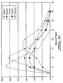
- the dimensions of the particles which can be produced using impulse atomisation can typically vary between 10 ⁇ m and 10mm and is dependent on a number of input control parameters. Referring to Figure 3, the size distribution typically obeys that of a log normal distribution and the slope of the distribution is proportional to the width of the distribution. It is evident from Figure 3 that the width of the particle size distribution for particles formed using impulse atomisation is significantly narrower than the particle size distribution for particles formed using conventional atomisation techniques.
- Narrower particle size distribution means that a significantly smaller portion of the produced powders are very fine (for example -325 mesh or smaller) or coarse (for example +40 mesh or greater) which in turn significantly reduces or eliminates the need for screening. As a consequence the amount of powder which is discarded is reduced which in turn improves production yield.
- Log-normal slope ( ⁇ ) of un-classified conventional air atomised zinc powder is typically above 2, more closely 2.4.
- Un-classified zinc powder produced by impulse atomisation has typically narrow size distribution and a log-normal slope ( ⁇ ) below 2 and typically below 1.6.
- typical parameters of the process are the frequency and the force applied to the plunger, the size of the aperture in the atomising plate, the distance between the plunger and the atomising plate and the atmospheric conditions in which the metal droplets are cooled and solidify.
- Table 1 provides examples of typical ranges for these parameters.
- Table 2 provides examples of how variation in these parameters may affect the powders obtained.
- Shapes which can be formed using the impulse atomisation technique include spherical 52 (Figure 5A), oblong 54 (not shown), teardrop as in 56, 58 and 60 ( Figures 5B and 5C) and strands 62 ( Figure 5D). As confirmed by the samples tabled in Table 3 hereinbelow, these shapes greatly effect the packing and densities of the resulting powder. This is distinct from the shape of particles formed using conventional air atomisation which, referring to the example in Figure 5E, are typically of an irregular shape (bone shape).
- impulse atomisation allows spherical powders to be obtained where the packing is optimal and the density is very high which in turn provides for an increased connectivity between the metallic particles.
- impulse atomisation also allows powders comprised of strands (i.e. particles which are acicular, very elongated and having a high aspect ratio) of zinc to be formed. Packing of the strands is achieved by intertwining the strands.
- Apparent density is a measure of the free packing of the powder and was measured according to ASTM #B212-99.
- the apparent density is measured using a hall flowmeter. Note that in order for the hall flowmeter to measure the apparent density the material must flow through an aperture at the lower end of a funnel which forms part of the flowmeter, which the high and very high aspect ratio (AR) strands are unable to do.
- Tap density is related to the packed density of the powder and was measured according to ASTM #B527-93.
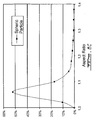
- FIG. 6A some typical distributions of the aspect ratios of stranded zinc alloy powders produced using impulse atomisation are shown. It is apparent from the graph that some very high aspect ratios are attainable using impulse atomisation.
- impulse atomisation One other benefit of impulse atomisation is that oxidation of the surface is greatly decreased due to the absence of atomising air jets, the corresponding reduction of air-zinc interactions and by the greatly increased rate of cooling.
- a variety of zinc alloy powders were prepared using impulse atomisation and conventional air atomisation and the amount of surface oxidation measured. The results are tabled in Table 4.
- Zinc alloying with some aluminum improves gassing, especially gassing after partial discharge. This effect is associated with the presence of aluminum in a metallic form, the amount of which is reduced when aluminum is oxidised.
- a controlled oxidation rate of the zinc droplets is demonstrated by the absence of dispersed nano-crystalline surface ZnO and by a significant drop in alkaline aluminum loss from the ABI alloy.
- the unit ⁇ l/g-d indicates the amount of hydrogen gas generated in micro litres per gram of zinc evolving from the anode per day.
- the fresh anode mix gassing is a measure of the hydrogen gas produced by fresh zinc within the anode kept at 71°C for 24 hours
- partially discharged anode mix gassing is a measure of the hydrogen gas evolving from the residual mixture within the anode once the fresh zinc has been partially discharged and subsequently kept at 71°C for 24 hours.
- test cells were assembled using identical manganese dioxide cathodes, current collectors and casings.
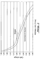
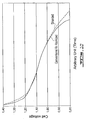
- FIG. 7 shows under a sustained load of 1 ohm the discharge voltage remains significantly higher for batteries having anodes or negative electrodes constructed using zinc alloys powders fabricated using impulse atomisation relative to the reference cells having anodes constructed of powders formed using conventional air atomisation. This is of course a benefit, in that many devices which operate such load conditions will indicate that the power source is depleted if the voltage drops below a threshold value.
- anodes fabricated with a zinc alloy powder comprised of 100% zinc strands revealed significantly improved performance characteristics.
- reduction of the amount of zinc by weight used to fabricate the anodes or negative electrodes of an alkaline cell from 67% to 62% was achieved while using a powder comprised of zinc strands fabricated using impulse atomisation.
- the high rate performance with a load of 1 ohm also improved up to 20% when compared with the reference batteries.
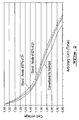
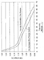
- Figure 9 shows that under high current drain conditions (i.e. a sustained current drain of 1 ampere) with varying amounts of zinc by weight in the cells (67% and 62%), the discharge voltage remains significantly higher for batteries having anodes or negative electrodes constructed using zinc alloy powders such as ABI fabricated according to impulse atomisation relative to the reference batteries.
- two LR-06 cells were assembled: the first LR-06 having an anode from zinc powder fabricated using conventional air atomisation; and the second having an anode from a stranded zinc powder fabricated using impulse atomisation.
- the LR-06 cells were otherwise the same using the same magnesium dioxide cathode, separator, current collector and casing.
- the anode included a zinc powder suspended in a gelled electrolyte comprising 98% by weight of KOH 40%/ZnO 3% and 2% by weight of polyacrylic acid (Carbopol TM 940) as gelling agent.
- electrochemical cells with anodes fabricated from stranded powders exhibit superior performance characteristics over those fabricated using conventional air atomised powders.
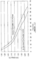
- the 1.0V cut-off which is typically used as an indicator to the electronics being supplied by the cell that the cell is depleted, was increased to 42 minutes from 34 minutes under the 1.0 ohm load (see Figure 11) and to 45 minutes from 36 minutes given load conditions drawing a continuous current of 1 ampere (see Figure 12).
- a melt of zinc alloy was prepared by melting electrolytic 99.995% zinc metal.
- Pure zinc and a variety of zinc alloys including zinc-bismuth (B alloy), zinc-bismuth-indium (Bl alloy), zinc-aluminum-bismuth-indium (ABI alloy), zinc-bismuth-indium-calcium (BIC alloy) and zinc-bismuth-indium-lead (BIP alloy) were prepared and then atomised using both conventional air-atomisation techniques and impulse atomisation. Following atomisation the zinc metal powders were classified and tested.
- a series of LR-06 cells were fabricated from powders derived from both the impulse atomisation process and conventional air atomisation process.
- the zinc anodes were fabricated from a zinc powder blended with a gelled electrolyte.
- the gelled electrolyte comprised 98% by weight of KOH 40%/ZnO 3% and 2% by weight of polyacrylic acid (Carbopol TM 940) as gelling agent.
- the zinc alloy powders were characterised and evaluated in terms LR06-cell performance at different zinc loads and the results tabled in Table 7 and Table 8. Note that the D50 column indicates the value below which 50% of the particles of zinc alloy powder produced were found. D50 was measured according to ASTM #214-99. Tap density, on the other hand, as stated above in reference to Table 4, is related to the packed density of the powder and was measured according to ASTM #B527-93.
- improved performance characteristics may also be derived from mixtures of the above produced zinc alloy powders.
- a given mixture is comprised of two or more types of zinc powders made by impulse atomisation or by impulse atomisation and conventional techniques and having different particle shapes and/or particle sizes distributed around different mean particle sizes which are then combined to form a hybrid powder.
- the powder mix in terms of both particle size and shape the performance characteristics of a given electrochemical cell can be optimised.
- powder fabricated using impulse atomisation was mixed with fine air atomised powder or conventional air atomised powder and tests performed in LR06 cells under two different regimes.
- the fine air atomised powder has a particle size distribution were 100% of the particles are less than 75 ⁇ m and the conventional air atomised powder has a particle size distribution within 425 ⁇ m and 54 ⁇ m.
Landscapes
- Chemical & Material Sciences (AREA)
- Chemical Kinetics & Catalysis (AREA)
- Electrochemistry (AREA)
- General Chemical & Material Sciences (AREA)
- Engineering & Computer Science (AREA)
- Nanotechnology (AREA)
- Battery Electrode And Active Subsutance (AREA)
- Powder Metallurgy (AREA)
- Manufacture Of Metal Powder And Suspensions Thereof (AREA)
Abstract
Description
- The present invention relates to a method for fabricating an anode of an electrochemical cell and the use of zinc alloy particles in a method for fabricating such an anode. In particular, the present invention relates to zinc powders which provide enhanced performance in alkaline and zinc-air cells.
- Primary alkaline cells are often used in applications where long lasting, high-energy output is needed, such as electronic portable devices and camera flashes. The alkaline cell technology has evolved significantly over the past 10 years or so. For instance, lower mercury and mercury-free cells were introduced in the 90's. Additionally, the high-rate performance of alkaline cells is consistently improving for both manganese dioxide cathodes and zinc anodes.
- Secondary, or rechargeable, zinc alkaline cells can also be used in similar applications as well as zinc-air cells. Those negative zinc electrodes are often similar to the zinc anodes of primary alkaline cells.
- Alkaline cells typically use, and derive their name from, an aqueous solution of an alkaline electrolyte such as potassium hydroxide. In their initial state these electrolytes are typically in a liquid form and, as the majority of commercially available off-the-shelf alkaline batteries are dry cells having an immobilised electrolyte, a gelling agent is typically added to the electrolyte during fabrication. Common gelling agents include carboxymethylcellulose, polyacrylic acid, sodium polyacrylate and salts. Trace amounts of other additives, such as anti-gassing agents including indium compounds or organics may in some cases be added to the electrolyte to inhibit the evolution of hydrogen gas, an unwanted by-product of the cell self-discharge process associated with the corrosion of the zinc.
- A predominant source of anodes, or negative electrodes, for household varieties of alkaline cells is zinc alloy powders mixed with a gelled potassium hydroxide/zinc oxide/water electrolyte. Indeed, zinc has a number of attributes which favour its use in the fabrication of anodes for disposable batteries including: a readily available supply of raw materials; low toxicity and a suitable electro-negativity or position in the galvanic series. Additionally, zinc-alkaline dry-cells typically have a low self discharge rate, good leakage resistance, good low temperature performance, relatively high capacity and relatively high energy density.
- Conventionally, the fabrication of battery-grade zinc alloy powder is carried out using the well known processes of gas atomisation or centrifugal atomisation, and as such these technologies are in current use by most zinc powder producers throughout the world. In gas or centrifugal atomisation a melt of zinc alloy is first prepared by melting metallic zinc and adding alloying elements to molten zinc, then atomising the melt and finally classifying the produced powders according to the size of particles produced and desired. In conventional air atomisation, for example, the molten zinc alloy is forced through a narrow nozzle at the output of which jets of air collide with the molten zinc alloy, thereby forming the zinc particles.
- Typically, the size distribution of the particles produced by the atomisation process may be controlled to some degree in the gas atomisation process, (i) by adjusting the metal to air ratio and, (ii) by classifying the produced powder, typically using mesh screens or the like, to remove particles which are either too fine or too coarse.
- Although the above conventional methods provide a means for fabricating powders from zinc, in order to render an alkaline cell with optimised operating characteristics, the zinc powder must be of high-purity metallic zinc, have precise zinc alloying, and a narrow particle size distribution.
- One of the drawbacks of the conventional means of fabrication is that, although the zinc alloy powder produced displays acceptable properties and characteristics and is suitable for use in constructing the anodes of alkaline cells, the wide particle size distribution may require sorting of the particles. Another drawback is that difficulties in modifying and controlling particle shape limits the ability to achieve specific density and particle packing, and consequently to achieve improved alkaline cell performance.
- Alternative atomisation technologies have been developed or studied to improve product performance. One of these techniques is impulse atomisation as disclosed in United States Patent No. 5,609,919 issued to Yuan et al, which describes a method and apparatus for producing particles from molten metal, including zinc, by forcing the molten metal through small apertures by applying regular train of impulses to the molten metal in the direction of the apertures and of sufficient amplitude to impel the molten metal through the apertures.
- US-A-5 609 919 discloses a method an an apparatus for producing discontinuous streams of an inorganic substance, such as a metal, an alloy, a molten salt, slag or matte, or a slurry of ceramic particles, wherein the substance, in the form of a melt or slurry, is maintained in a container at the bottom of which at least one nozzle is provided containing at least one opening having a thickness that is large enough to withstand mechanical and thermal stresses and the melt or slurry is pushed through such opening(s) by means of an impulse applicator positioned over the opening(s) and operating in a periodic manner.
- US-A-6 344 295 disclose rechargeable cells employing mercury-and lead-free zinc-bismuth alloys as negative active materials. Such cells demonstrate low after-cycle gassing, improved cumulative discharge capacities and initial discharge performances comparable to that of rechargeable cells that employ leaded zinc powders as negative anode materials.
- The present invention actresses the above and other drawbacks by providing for a method for fabricating an anode of an electrochemical cell as claimed in claim 1 and the use of zinc alloy particles in such a method as claimed in claim 7.
-
- Figure 1 is a cut-way perspective view of an "AA" (or LR-06) electrochemical cell produced in accordance with an illustrative embodiment of the present invention;
- Figure 2 is a schematic diagram of an assembly for fabricating zinc powders according to impulse atomisation;
- Figure 3 provides particle size distributions for a variety of zinc powders fabricated using both impulse atomisation and air atomisation;
- Figure 4 provides illustrative embodiments of enhanced particle shapes for zinc powders;
- Figures 5A through 5D provide an electron microscope images of enhanced particle shapes for zinc powders;
- Figure 5E provides a comparative electron microscope image of the particle shapes of zinc powders formed by conventional air atomisation;
- Figures 6A through 6C provide an illustrative comparison of aspect ratios between zinc alloy powders formed using impulse atomisation and conventional air atomisation;
- Figure 7 provides the discharge curves of LR-06 cells containing zinc strands where 67% of zinc constitute the anode versus LR-06 cells containing 67% conventional zinc powder under 1.0 ohm continuous discharge;
- Figure 8 provides the discharge curves of LR-06 cells containing zinc strands where 62% of zinc constitute the anode versus LR-06 cells containing 67% conventional zinc powder under 1.0 ohm continuous discharge;
- Figure 9 provides the discharge curves of LR-06 cells containing zinc strands where 67% and 62% of zinc constitute the anode versus LR-06 cells containing 67%, conventional zinc powder under 1 ampere continuous discharge;
- Figure 10 provides the discharge curves of LR-06 cells containing zinc strands where 62% of zinc constitute the anode versus LR-06 cells containing 67% conventional zinc powder under 3.9 ohm continuous discharge.
- Figure 11 provides the discharge curves of LR-06 cells containing zinc strands where 67% of zinc constitute the anode versus LR-06 cells containing 67% conventional zinc powder under 1.0 ohm continuous discharge.
- Figure 12 provides the discharge curves of LR-06 cells containing zinc strands where 67% of zinc constitute the anode versus LR-06 cells containing 67% conventional zinc powder under 1 ampere continuous discharge.
- Referring to Figure 1 an illustrative embodiment of an electrochemical cell produced in accordance with an illustrative embodiment of the present invention will now be described. The electrochemical cell, generally referred to using the
reference numeral 10, is comprised of agelled zinc anode 12 separated from aManganese dioxide cathode 14 by apaper separator 16. Acasing 18 typically fabricated from a conductive material such as steel (or PVC with a conductive lining) encases thecathode 14 and acts as the cathode current collector. Thecasing 18 is in electrical contact with thepositive cap 20. An anodecurrent collector 22 fabricated from a highly conductive material such as copper is inserted into the agelled zinc anode 12 from the end opposite to that of thepositive cap 20. The anodecurrent collector 22 is in electrical contact with thenegative cap 24. A layer ofinsulating material 26 separates thecathode 14 andcasing 18 from coming into contact with thenegative cap 24. Additionally,air vents 28 are provided for to allow any hydrogen gas which may evolve due to the corrosion of zinc to escape. Thegelled zinc anode 12 is comprised of zinc alloy powder suspended in a potassium hydroxide (KOH) electrolyte treated with a gelling agent. - As discussed above, impulse atomisation allows the atomisation of zinc and zinc alloys into zinc powders with unique physical characteristics including, for example, the shape of the particles and the particle size distribution. Other unique properties are directly associated with the above characteristics, for example a variety of particle packing and densities varying between 0.5 and 4.6 g/cc can be achieved. Therefore, zinc and zinc alloys powder produced using impulse atomisation lend themselves exceptionally well to the fabrication of anodes and negative electrodes for electrochemical cells.
- Use of these powders as a component in the anodes or negative electrodes of electrochemical cells provides zinc electrodes with low gassing rate in alkaline media, and a significant service increase under a variety of operating conditions, notably during high-rate discharge.
- Referring now to Figure 2 there is disclosed an assembly for fabricating zinc powders according to a modified version of impulse atomisation generally referred to using the
numeral 30. The assembly comprises a tundish 32 ofmolten zinc metal 34 into which is placed aplunger 36. The tundish 32 is manufactured from refractory or metal capable of withstanding the temperature of the molten zinc alloy. Theupper end 38 of the piston is attached to a source ofvibration 40. Application of the vibrations to theplunger 36 causes thelower end 42 of theplunger 36 to move relative to the tundish 32 and anatomising plate 44 attached to the bottom of the tundish 32. Themolten zinc metal 34 flows freely between thelower end 42 of theplunger 36 and theatomising plate 44. Movement of thelower end 42 of theplunger 36 relative to the atomisingplate 44 causes themolten zinc metal 34 to be forced through small orifices as in 45 in the atomisingplate 44 thereby forming zinc droplets ofmolten zinc 46. The molten zinc droplets pass through a particle formation chamber 48 into a coolingchamber 50 where they are cooled in air or another gas, collected, classified and packaged. - Impulse atomisation allows the dimensions of the particles to be accurately controlled using the
orifices 45 in theatomisation plate 44, the position of theplunger 36, the frequency and amplitude of the vibrations applied to theplunger 36 and the atmosphere of the formation chamber 48. - On one hand, the length of travel of the plunger 36 (i.e. the amplitude of the vibrations applied to the plunger 36) in large measure dictates the length of segments of molten zinc alloy which are ejected into the formation chamber 48.
- On the other hand, selection of an appropriate shape for the
orifices 46 also allows for the shape of the particles to be controlled. In the case of elongate segments produced through a round or similar convex polyhedral shaped opening, the elongate segment will be thread-like or acicular. In the case of elongate segments produced through a slit, the elongate segments will be laminar, forming sheets, flat or curved, whose smallest lateral dimension is the thickness of the segment. In the case of more complicated aperture shapes, such as a cross, the smallest lateral dimension will be the thickness of one of the arms of the cross, but the length of the fluid segment may also be several times the width of the arms of the cross. - Additionally, parameters such as rate of cooling can be varied to promote the solidification of the elongated segments of molten zinc alloy solidify prior to their breaking up into spherical droplets. The rate of cooling depends on the surface tension of the zinc alloy, heat transfer from the zinc alloy and the gas through which the zinc alloy passes. For example, an acicular segment will produce an acicular powder if solidified before break up occurs.
- The dimensions of the particles which can be produced using impulse atomisation can typically vary between 10µm and 10mm and is dependent on a number of input control parameters. Referring to Figure 3, the size distribution typically obeys that of a log normal distribution and the slope of the distribution is proportional to the width of the distribution. It is evident from Figure 3 that the width of the particle size distribution for particles formed using impulse atomisation is significantly narrower than the particle size distribution for particles formed using conventional atomisation techniques.
- Narrower particle size distribution means that a significantly smaller portion of the produced powders are very fine (for example -325 mesh or smaller) or coarse (for example +40 mesh or greater) which in turn significantly reduces or eliminates the need for screening. As a consequence the amount of powder which is discarded is reduced which in turn improves production yield.
- Log-normal slope (σ) of un-classified conventional air atomised zinc powder is typically above 2, more closely 2.4. Un-classified zinc powder produced by impulse atomisation has typically narrow size distribution and a log-normal slope (σ) below 2 and typically below 1.6.
- As stated above, typical parameters of the process are the frequency and the force applied to the plunger, the size of the aperture in the atomising plate, the distance between the plunger and the atomising plate and the atmospheric conditions in which the metal droplets are cooled and solidify. By individually varying these parameters different particle shapes, size distributions, and powder densities can be achieved. Table 1, for example, provides examples of typical ranges for these parameters. Table 2 provides examples of how variation in these parameters may affect the powders obtained.
TABLE 1 Frequency (Hz) Force Applied (newtons) Plunger Distance (mm) Atomising Apertures (µm) Atmospheric Conditions 20 to 1000 44.5 to 400 (10 to 90 lbf) 1 to 7 40 to 500 100 % Air 100% Nitrogen (or any other inert gas) 100% Oxygen 0 to 20% Oxygen (the remaining being inert gas)TABLE 2 Parameters Impulse Atomisation Conditions Frequency (Hz) 40 110 80 Force applied (newtons) 133.5 (30 lbf) 267 (60 lbf) 245 (55 lbf) Aperture size (µm) 100 150 150 Atmosphere Air Air 0.25% O2 Powder characteristics Strand Strand Spherical Tap Density (g/cc) 2.4 3.03 4.2 - Shapes which can be formed using the impulse atomisation technique include spherical 52 (Figure 5A), oblong 54 (not shown), teardrop as in 56, 58 and 60 (Figures 5B and 5C) and strands 62 (Figure 5D). As confirmed by the samples tabled in Table 3 hereinbelow, these shapes greatly effect the packing and densities of the resulting powder. This is distinct from the shape of particles formed using conventional air atomisation which, referring to the example in Figure 5E, are typically of an irregular shape (bone shape).
- The ability to more accurately control the characteristics of the powders provides a greater control over the performance characteristics of the resultant electrochemical cells as measured in terms of discharge rate, gassing, etc.. For example, impulse atomisation allows spherical powders to be obtained where the packing is optimal and the density is very high which in turn provides for an increased connectivity between the metallic particles. On the other hand, by adjusting the conditions under which the droplets of molten zinc metal are formed, impulse atomisation also allows powders comprised of strands (i.e. particles which are acicular, very elongated and having a high aspect ratio) of zinc to be formed. Packing of the strands is achieved by intertwining the strands. This type of intertwining gives rise to a low density powder, while strand-like particles greatly increase the connectivity between particles when compared to spherical particles. Finally, by once again adjusting the conditions under which the droplets of molten zinc metal are formed, it has now been found that teardrop shaped particles with a variety of well-controlled aspect ratios can be formed which provide a favourable combination of both high apparent density and high connectivity, thereby uniting the advantages of both spherical and stranded forms.
- In order to determine the densities, a series of test samples were prepared using both impulse atomisation and a conventional air atomisation and the resulting samples tested in regard to their density. The results are Tabled in Table 3.
TABLE 3 Atomisation process Shape Apparent Density (g/cc) (ASTM #B212-99) Tap Density (g/cc) (ASTM #B527-93) Impulse atomisation Strand very high AR N/A 0.63 Strand high AR N/A 1.42 Strand 1.82 2.02 Strand 1.98 2.37 Strand 2.45 2.59 Strand 2.76 3.02 Tear drop tailing 3.20 3.27 Tear drop tailing 3.55 3.18 Spherical 4.10 4.17 Spherical 4.16 4.3 Conventional air atomisation Irregular/Bone shape 3.03 3.40 - Apparent density is a measure of the free packing of the powder and was measured according to ASTM #B212-99. The apparent density is measured using a hall flowmeter. Note that in order for the hall flowmeter to measure the apparent density the material must flow through an aperture at the lower end of a funnel which forms part of the flowmeter, which the high and very high aspect ratio (AR) strands are unable to do. Tap density, on the other hand, is related to the packed density of the powder and was measured according to ASTM #B527-93.
- Referring now to Figure 6A, some typical distributions of the aspect ratios of stranded zinc alloy powders produced using impulse atomisation are shown. It is apparent from the graph that some very high aspect ratios are attainable using impulse atomisation. Zinc alloy powders produced using conventional air atomisation, on the other hand, and as graphed in Figure 6B, and generally spherical particles, as graphed in Figure 6C, have a relatively small aspect ratio.
- One other benefit of impulse atomisation is that oxidation of the surface is greatly decreased due to the absence of atomising air jets, the corresponding reduction of air-zinc interactions and by the greatly increased rate of cooling. A variety of zinc alloy powders were prepared using impulse atomisation and conventional air atomisation and the amount of surface oxidation measured.
The results are tabled in Table 4.TABLE 4 Atomization process Alloy Chemistry (ppm) Al Bi In Pb ZnO (%) ZnO Ratio to Reference Impulse atomisation process (strand shaped) 50 100 200 0.03 0.25 70 100 200 0.04 0.33 60 100 200 0.03 0.25 75 100 200 0.02 0.17 Conventional air atomisation 100 100 200 0.12 1 Impulse atomisation process (strand shaped) 300 300 0.08 0.15 300 300 0.16 0.30 300 300 0.09 0.17 Conventional air atomisation 300 300 0.54 1 Impulse atomisation process (strand shaped) 500 500 500 0.06 0.43 Conventional air atomisation 500 500 500 0.14 1 - Note that in the table above the amount of zinc oxide produced is expressed relative to the total amount of zinc atomised. Experimental results show that oxidation is reduced up to 85% relative to that produced during conventional air atomisation. Indeed, when using air atomisation experimental results reveal that a dispersed nano-crystalline surface zinc oxide is formed during the initial stages, immediately after the molten zinc metal is pulverised by the air jets into metal droplets. The kinetics of oxidation are in large part determined by the oxidising conditions occurring around the zinc droplets in the atomisation spray.
- The effect of oxidation on melt droplets is easily observed during the manufacture of metal powders from zinc alloyed with aluminum, bismuth and indium (ABI). Experimentation reveals that a significant portion of aluminum is instantaneously dissolved when an ABI powder produced using conventional air atomisation is immersed in alkaline solutions, and this without any significant evolution of hydrogen gas. Typically, 50% of added aluminum is lost during alkaline immersion, but this loss may reach up to 75% for some alloys containing about 200 ppm of aluminum, or depending upon atomisation parameters such as high melt or atomising air temperature. The effective aluminum concentration in zinc particles is therefore much lower.
- Zinc alloying with some aluminum improves gassing, especially gassing after partial discharge. This effect is associated with the presence of aluminum in a metallic form, the amount of which is reduced when aluminum is oxidised.
- It is apparent that a strong force is acting on the aluminum, aluminum oxidation. Therefore it seems likely that aluminum is reacting and accumulating on the droplet surface as an oxide according to this mechanism:
- Fast aluminum oxidation occurs near the surface of zinc alloy droplet immediately following formation;
- aluminum diffuses from bulk to the droplet's surface prior to particle solidification; and
- further aluminum oxidation occurs until solidification is completed.
- A controlled oxidation rate of the zinc droplets is demonstrated by the absence of dispersed nano-crystalline surface ZnO and by a significant drop in alkaline aluminum loss from the ABI alloy.
- A series of samples of zinc alloy containing aluminum were prepared and zinc alloy powders formed using impulse atomisation and conventional air atomisation techniques. The powders were then immersed in a KOH electrolyte and the remaining Al then measured. The results are tabled in Table 5.
TABLE 5 Atomisation process Aluminium Content (ppm) Alloyed Al Al Remaining After Immersion in KOH Aluminium Ratio Impulse atomisation 125 119 95% 59 51 86% Conventional - air atomisation 109 54 49% - In order to analyse the effects of impulse atomisation on gassing a series of samples of zinc alloy were prepared. These alloys were then used to fabricate powders using both the impulse atomisation techniques and conventional air atomisation techniques. The powders were then dispersed in a gelled KOH electrolyte and the gassing measured. The results are tabled in Table 6.
TABLE 6 Atomisation process Alloy Chemistry (ppm) Anode Mix Gassing (µl/g-d) Bi In Al Pb Fresh Anode Mix Partially Discharged Anode Mix Impulse atomisation process 300 300 7.1 42 300 300 4.2 37 Typical air atomisation 300 300 10 105 Impulse atomisation process 100 200 100 1.4 41 100 200 100 5.6 32 Typical air atomisation 100 200 100 6.0 30 Impulse atomisation process 100 13.2 112 Typical air atomisation 100 138 197 Impulse atomisation process 500 500 500 9.6 20 Typical air atomisation 500 500 500 4.8 77 - Note that the unit µl/g-d indicates the amount of hydrogen gas generated in micro litres per gram of zinc evolving from the anode per day. Additionally, the fresh anode mix gassing is a measure of the hydrogen gas produced by fresh zinc within the anode kept at 71°C for 24 hours, whereas partially discharged anode mix gassing is a measure of the hydrogen gas evolving from the residual mixture within the anode once the fresh zinc has been partially discharged and subsequently kept at 71°C for 24 hours.
- It is apparent from the above results that the gassing rates of anodes, or negative electrodes, fabricated from powdered zinc and an alkaline electrolyte such as potassium hydroxide (KOH), zinc oxide (ZnO) and a gelling agent are significantly reduced through impulse atomisation. For example, fabrication of zinc alloy particles using impulse atomisation and zinc alloyed with either bismuth, bismuth-indium, bismuth-indium-aluminium, or bismuth-indium-lead provided for reduced gassing rates significantly over powders fabricated using conventional air atomisation techniques.
- In order to test performance a series of LR-06 test cells and LR-06 reference cells were assembled. All test cells and reference cells were assembled using identical manganese dioxide cathodes, current collectors and casings.
- Anodes fabricated with a zinc alloy powder comprised of 100% zinc strands revealed significantly improved performance characteristics. Figure 7 shows under a sustained load of 1 ohm the discharge voltage remains significantly higher for batteries having anodes or negative electrodes constructed using zinc alloys powders fabricated using impulse atomisation relative to the reference cells having anodes constructed of powders formed using conventional air atomisation. This is of course a benefit, in that many devices which operate such load conditions will indicate that the power source is depleted if the voltage drops below a threshold value.
- Additionally, anodes fabricated with a zinc alloy powder comprised of 100% zinc strands revealed significantly improved performance characteristics. For example, referring to Figure 8, in comparative tests with reference batteries having anodes comprised of zinc powders fabricated using conventional air atomisation techniques, reduction of the amount of zinc by weight used to fabricate the anodes or negative electrodes of an alkaline cell from 67% to 62% was achieved while using a powder comprised of zinc strands fabricated using impulse atomisation. The high rate performance with a load of 1 ohm also improved up to 20% when compared with the reference batteries.
- Furthermore, Figure 9 shows that under high current drain conditions (i.e. a sustained current drain of 1 ampere) with varying amounts of zinc by weight in the cells (67% and 62%), the discharge voltage remains significantly higher for batteries having anodes or negative electrodes constructed using zinc alloy powders such as ABI fabricated according to impulse atomisation relative to the reference batteries.
- Finally, reduction in the amount of zinc by weight in the anode of an alkaline battery by approximately 10% (from 67% to 62%) while using zinc strands having large aspect ratio fabricated using impulse atomisation revealed that, during low rate conditions (i.e. under a continuous load of 3.9 ohms), the capacity of the cell was increased by approximately 5% over that of the reference batteries having anodes comprised of 67% by weight conventional air atomised zinc powders. The results for a low rate discharge are provided in Figure 10.
- In order to test the actual discharge rates of zinc powder anodes, two LR-06 cells were assembled: the first LR-06 having an anode from zinc powder fabricated using conventional air atomisation; and the second having an anode from a stranded zinc powder fabricated using impulse atomisation. The LR-06 cells were otherwise the same using the same magnesium dioxide cathode, separator, current collector and casing. Additionally, the anode included a zinc powder suspended in a gelled electrolyte comprising 98% by weight of
KOH 40%/ZnO 3% and 2% by weight of polyacrylic acid (Carbopol™ 940) as gelling agent. - In order to test cell performance under constant continuous load, a load of 1 ohm was placed between the positive and negative terminals of the cells and the fluctuation in cell voltage measured over time. The results are graphed in Figure 11. Similarly, in order to test the cell performance under constant continuous current, a continuous current of 1 ampere was drawn from the cell. The results are graphed in Figure 12.
- It will now be apparent to one of ordinary skill in the art that electrochemical cells with anodes fabricated from stranded powders exhibit superior performance characteristics over those fabricated using conventional air atomised powders. In particular, the 1.0V cut-off, which is typically used as an indicator to the electronics being supplied by the cell that the cell is depleted, was increased to 42 minutes from 34 minutes under the 1.0 ohm load (see Figure 11) and to 45 minutes from 36 minutes given load conditions drawing a continuous current of 1 ampere (see Figure 12).
- A melt of zinc alloy was prepared by melting electrolytic 99.995% zinc metal. Pure zinc and a variety of zinc alloys, including zinc-bismuth (B alloy), zinc-bismuth-indium (Bl alloy), zinc-aluminum-bismuth-indium (ABI alloy), zinc-bismuth-indium-calcium (BIC alloy) and zinc-bismuth-indium-lead (BIP alloy) were prepared and then atomised using both conventional air-atomisation techniques and impulse atomisation. Following atomisation the zinc metal powders were classified and tested.
- A series of LR-06 cells were fabricated from powders derived from both the impulse atomisation process and conventional air atomisation process. The zinc anodes were fabricated from a zinc powder blended with a gelled electrolyte. The gelled electrolyte comprised 98% by weight of
KOH 40%/ZnO 3% and 2% by weight of polyacrylic acid (Carbopol™ 940) as gelling agent. - Two varieties of gelled anodes were fabricated, the first comprising 67% by weight zinc powder and 33% by weight gelled electrolyte and the second comprising 62% by weight zinc powder and 38% by weight gelled electrolyte. The control anode was fabricated from 67% by weight zinc powder and 33% by weight of gelled electrolyte. Once the mix of zinc and gelled electrolyte was homogeneous, the resulting paste was inserted in LR06 alkaline cell to form the anode. Referring back to Figure 1, the manner in which those cells were constructed is shown.
- The zinc alloy powders were characterised and evaluated in terms LR06-cell performance at different zinc loads and the results tabled in Table 7 and Table 8. Note that the D50 column indicates the value below which 50% of the particles of zinc alloy powder produced were found. D50 was measured according to ASTM #214-99. Tap density, on the other hand, as stated above in reference to Table 4, is related to the packed density of the powder and was measured according to ASTM #B527-93.
TABLE 7 Powder Particle Characteristics Image Analysis PSD (ASTM #214-99) Density (ASTM #B527-93) Average Aspect Ratio Average Width (µm) Average Length (µm) D50 (µm) Tap Density Type 1 10 166 1605 530 3.1 Type 2 11 207 2060 340 2.8 Type 3 20 101 1771 360 2.5 Type 4 14 134 1625 355 3.1 Type 5 18 160 2053 405 2.7 Type 6 20 96 1622 315 2.3 Type 7 21 125 1925 340 2.4 Type 8 22 93 1508 280 2.4 Type 9 23 106 1900 420 2.3 Type 10 20 105 1880 290 2.4 Type 11 18 91 1446 300 2.6 Type 12 19 87 1471 320 2.6 Type 13 21 84 1545 400 2.3 Reference 2 151 292 150 3.4 TABLE 8 Alloy Chemistry (ppm) LR06 to 1.0V Cut-Off vs. Reference (%) Bi In Al Pb Ca 1000 mA 1 ohm 62% Zn 67% Zn 62% Zn 67% Zn Type 1 300 300 95 96 97 99 Type 2 300 300 103 100 91 101 Type 3 300 300 101 101 100 102 Type 4 300 300 101 104 96 96 Type 5 300 300 92 98 100 99 Type 6 300 300 107 113 107 114 Type 7 300 300 107 107 107 107 Type 8 300 300 121 120 106 110 Type 9 100 200 100 106 115 123 125 Type 10 100 200 100 122 115 128 126 Type 11 100 97 98 100 94 Type 12 500 500 500 88 90 96 100 Type 13 250 250 150 108 115 110 114 Reference 100 200 100 100 100 100 100 - Additionally, improved performance characteristics may also be derived from mixtures of the above produced zinc alloy powders. A given mixture is comprised of two or more types of zinc powders made by impulse atomisation or by impulse atomisation and conventional techniques and having different particle shapes and/or particle sizes distributed around different mean particle sizes which are then combined to form a hybrid powder. By adjusting the powder mix in terms of both particle size and shape the performance characteristics of a given electrochemical cell can be optimised.
- Referring now to Table 9, powder fabricated using impulse atomisation was mixed with fine air atomised powder or conventional air atomised powder and tests performed in LR06 cells under two different regimes. The fine air atomised powder has a particle size distribution were 100% of the particles are less than 75 µm and the conventional air atomised powder has a particle size distribution within 425 µm and 54 µm.
TABLE 9 Powder Air Atomised Powder Added LR06 to 1.0V Cut-Off vs. Reference Fine Powder Conventional Powder 1.5 W 1A 1W Intermittent Type 6 - - 109% 113% 109% 20% - 114% 103% 50% - 130% 107% - 20% 102% 100% - 50% 99% 97% Type 10 - - 109% 115% 115% 20% - 131% 109% 50% - 116% 98% - 20% 116%. 119% - 50% 107% 118% Reference - - 100% 100% 100% - Furthermore, improved performance characteristics may also be achieve from derived formulations of the anode mix varying the concentration of gelling agent for instance. A stranded zinc powder was mixed with an electrolyte comprising varying amounts of the polyacrylic gelling agent Carbopol™ 940. The results are tabled in Table 10.
TABLE 10 Powder Chemistry (ppm) Carbopol™ (%) LR06 to 1.0V Cut-Off vs. Reference Bi In 1A Type 7 300 300 0.60% 107% 0.30% 106% 0.15% 112%
Claims (29)
- A method for fabricating a powder for use in an anode of an electrochemical cell, the method comprising the steps of:(a) providing a molten zinc alloy;(b) atomising said molten zinc alloy by impulse atomisation to produce zinc alloy particles;(c) recovering said particles, wherein said recovered particles have a particle size distribution having a log normal distribution slope of less than 2, preferably less than 1.6, exhibit an average aspect ratio of between 8 and 22 and wherein a major portion of said recovered particles are of a teardrop, acicular or stranded shape; and(d) fabricating an anode from said recovered particles, wherein the recovered particles are suspended in a fluid medium.
- The method of claim 1, wherein said impulse atomisation has a frequency of between 20 and 1000Hz, a force applied to the plunger of between 44.5 and 40 newtons, a plunger distance of between 1 to 7 mm and atomising apertures of between 40 and 500µm.
- The method of claim 1 or 2, wherein said atomising step further comprises cooling said particles in an atmosphere comprising a gas selected from the group consisting of air, inert gas, oxygen and a mixture of 0 to 20% oxygen with the remainder being inert gas.
- The method of claim 3, wherein said inert gas is selected from the group consisting of nitrogen, helium, argon and any mix of nitrogen, helium and argon.
- The method of claim 1, wherein a major portion of said recovered particles are teardrop.
- The method of claim 1, wherein a major portion of said recovered particles are acicular or stranded.
- Use of zinc alloy particles having a particle size distribution with a log normal slope of less than 2, preferably less than 1.6 and an average aspect ratio of between 8 and 22 wherein a major portion of said zinc alloy particles are of a teardrop, acicular or stranded shape in method for fabricating an anode of an electrochemical cell, wherein the zinc alloy particles are suspended in a fluid medium.
- The use of claim 7, wherein said zinc alloy is comprised of pure zinc alloyed with bismuth and indium.
- The use of claim 7, wherein said zinc alloy particles have an average length between 100µm and 3000µm, preferably between 500µm and 2000µm.
- The use of claim 7. wherein said zinc alloy particles have an average width between 40µm and 1000µm, preferably between 40µm and 200µm.
- The use of claims 7 to 10, further comprising up to 50% and preferably up to 20% of a second zinc metal or zinc alloy powder having an average aspect ratio of 2 and an average particle size of between 54µm and 425µm.
- The use of claims 7 to 10, further comprising up to 50% and preferably up to 20% of a second zinc metal powder having an average particle size of less than 75µm.
- The use as in claim 11 or 12, wherein said particles and said second powder are formed from the same zinc alloy in terms of alloying elements and amounts of said alloying elements.
- The use of claim 8, wherein said zinc alloy comprises between 50 to 1000 ppm bismuth, preferably between 100 to 500 ppm, bismuth.
- The use of claim 8, wherein said zinc alloy comprises between 50 to 1000 ppm indium, preferably between 100 to 500 ppm, indium.
- The use of claim 8, wherein said zinc alloy further comprises aluminum.
- The use of claim 16, wherein said zinc alloy further comprises between 20 to 1000ppm aluminum, preferably between 50 to 200ppm, aluminum.
- The use of claims 8 to 17, wherein said zinc alloy further comprises calcium.
- The use of claim 18, wherein said zinc alloy further comprises between 20 to 1000ppm calcium, preferably between 50 to 200ppm, calcium.
- The use of claims 8 to 17, wherein said zinc alloy further comprises lead.
- The use of claim 20, wherein said zinc alloy further comprises between 50 to 1000ppm lead, preferably between 50 to 500ppm, lead.
- The method of claims 1 to 6, wherein said fluid medium is a gelled KOH electrolyte.
- The method of claim 22, wherein said gelled KOH electrolyte comprises 98°/o by weight of KOH 40%/ZnO 3% and 2% by weight of a gelling agent.
- The method of claim 23, wherein said gelling agent is polyacrylic acid.
- The method of claim 24, wherein said polyacrylic acid is Carbopol™ 940.
- The use of claims 7 to 21, wherein said fluid medium is a gelled KOH electrolyte.
- The use of claim 26, wherein said gelled KOH electrolyte comprises 98% by weight of KOH 40%/ZnO 3% and 2% by weight of a gelling agent.
- The use of claim 27, wherein said gelling agent is polyacrylic acid.
- The use of claim 28, wherein said polyacrylic acid is Carbopol™ 940.
Applications Claiming Priority (3)
| Application Number | Priority Date | Filing Date | Title |
|---|---|---|---|
| US40078702P | 2002-08-05 | 2002-08-05 | |
| US400787P | 2002-08-05 | ||
| PCT/CA2003/001170 WO2004012886A2 (en) | 2002-08-05 | 2003-08-05 | Zinc powders for use in electrochemical cells |
Publications (2)
| Publication Number | Publication Date |
|---|---|
| EP1539411A2 EP1539411A2 (en) | 2005-06-15 |
| EP1539411B1 true EP1539411B1 (en) | 2007-04-18 |
Family
ID=31495879
Family Applications (1)
| Application Number | Title | Priority Date | Filing Date |
|---|---|---|---|
| EP03766094A Expired - Lifetime EP1539411B1 (en) | 2002-08-05 | 2003-08-05 | Use in electrochemical cells of a zinc powder |
Country Status (8)
| Country | Link |
|---|---|
| US (1) | US20040115532A1 (en) |
| EP (1) | EP1539411B1 (en) |
| AT (1) | ATE359890T1 (en) |
| AU (1) | AU2003257294A1 (en) |
| CA (1) | CA2495032A1 (en) |
| DE (1) | DE60313334T2 (en) |
| ES (1) | ES2285193T3 (en) |
| WO (1) | WO2004012886A2 (en) |
Families Citing this family (11)
| Publication number | Priority date | Publication date | Assignee | Title |
|---|---|---|---|---|
| US7323031B2 (en) * | 2003-01-09 | 2008-01-29 | Grillo-Werke Ag | Zinc powder or zinc alloy powder with inhomogeneous bulk density for alkaline batteries |
| US7947393B2 (en) * | 2003-11-14 | 2011-05-24 | Eveready Battery Company, Inc. | Alkaline electrochemical cell |
| US7364819B2 (en) | 2004-06-28 | 2008-04-29 | Eveready Battery Company, Inc. | Alkaline electrochemical cell with a blended zinc powder |
| WO2006045470A1 (en) * | 2004-10-20 | 2006-05-04 | Umicore | Alloyed zinc powders for alkaline batteries with high pyknometer density |
| US7291186B2 (en) * | 2004-11-01 | 2007-11-06 | Teck Cominco Metals Ltd. | Solid porous zinc electrodes and methods of making same |
| DE602006003893D1 (en) | 2005-05-19 | 2009-01-08 | Umicore Nv | ALLOY ZINC POWDER FOR ALKALI BATTERIES WITH PARTICLES THAT ARE BORED BY AT LEAST ONE HOLE |
| EP1912755A1 (en) * | 2005-08-12 | 2008-04-23 | Dunwilco (1198) Limited | Process for producing metal flakes |
| US20070264572A1 (en) * | 2006-05-09 | 2007-11-15 | Zuraw Michael J | Battery Anodes |
| JP4435801B2 (en) * | 2007-04-10 | 2010-03-24 | パナソニック株式会社 | Alkaline battery |
| EP2323205A1 (en) * | 2008-09-12 | 2011-05-18 | Panasonic Corporation | Mercury-free alkaline dry battery |
| US8900761B2 (en) * | 2010-05-24 | 2014-12-02 | The Regents Of The University Of Colorado, A Body Corporate | Zinc anode battery with boron nitride coated zinc particles |
Family Cites Families (14)
| Publication number | Priority date | Publication date | Assignee | Title |
|---|---|---|---|---|
| BE1003415A6 (en) * | 1989-11-10 | 1992-03-17 | Acec Union Miniere | Zinc powder for alkaline batteries. |
| CA2077796A1 (en) * | 1992-09-09 | 1994-03-10 | Jean-Yves Huot | Low-lead zinc alloy powders for zero-mercury alkaline batteries |
| US5609919A (en) * | 1994-04-21 | 1997-03-11 | Altamat Inc. | Method for producing droplets |
| BE1008626A3 (en) * | 1994-08-23 | 1996-06-04 | Union Miniere Sa | Zinc powder for alkaline batteries. |
| US6022639A (en) * | 1996-11-01 | 2000-02-08 | Eveready Battery Company, Inc. | Zinc anode for an electochemical cell |
| US6284410B1 (en) * | 1997-08-01 | 2001-09-04 | Duracell Inc. | Zinc electrode particle form |
| US6521378B2 (en) * | 1997-08-01 | 2003-02-18 | Duracell Inc. | Electrode having multi-modal distribution of zinc-based particles |
| US6015636A (en) * | 1998-06-01 | 2000-01-18 | Electric Fuel Ltd. | Enhanced performance zinc |
| US6344295B1 (en) * | 1999-04-30 | 2002-02-05 | Noranda, Inc. | Zinc alloy powder for use in rechargeable cells |
| US6333127B1 (en) * | 1999-09-30 | 2001-12-25 | Eveready Battery Company, Inc. | Electrochemical cell and cell assembly process |
| US6479188B1 (en) * | 1999-10-13 | 2002-11-12 | The Gillette Company | Cathode tube and method of making the same |
| US6602629B1 (en) * | 2000-05-24 | 2003-08-05 | Eveready Battery Company, Inc. | Zero mercury air cell |
| US6627349B2 (en) * | 2001-04-26 | 2003-09-30 | Eveready Battery Company, Inc. | Electrode for an electrochemical cell |
| US7008723B2 (en) * | 2001-08-21 | 2006-03-07 | Ecosol Solar Technologies Inc. | Method of manufacture of an anode composition for use in a rechargeable electrochemical cell |
-
2003
- 2003-08-05 AU AU2003257294A patent/AU2003257294A1/en not_active Abandoned
- 2003-08-05 WO PCT/CA2003/001170 patent/WO2004012886A2/en active IP Right Grant
- 2003-08-05 US US10/634,651 patent/US20040115532A1/en not_active Abandoned
- 2003-08-05 EP EP03766094A patent/EP1539411B1/en not_active Expired - Lifetime
- 2003-08-05 DE DE60313334T patent/DE60313334T2/en not_active Expired - Lifetime
- 2003-08-05 CA CA002495032A patent/CA2495032A1/en not_active Abandoned
- 2003-08-05 ES ES03766094T patent/ES2285193T3/en not_active Expired - Lifetime
- 2003-08-05 AT AT03766094T patent/ATE359890T1/en not_active IP Right Cessation
Non-Patent Citations (1)
| Title |
|---|
| None * |
Also Published As
| Publication number | Publication date |
|---|---|
| DE60313334T2 (en) | 2008-01-03 |
| ATE359890T1 (en) | 2007-05-15 |
| AU2003257294A1 (en) | 2004-02-23 |
| CA2495032A1 (en) | 2004-02-12 |
| ES2285193T3 (en) | 2007-11-16 |
| DE60313334D1 (en) | 2007-05-31 |
| US20040115532A1 (en) | 2004-06-17 |
| WO2004012886A3 (en) | 2004-05-13 |
| EP1539411A2 (en) | 2005-06-15 |
| WO2004012886B1 (en) | 2004-07-08 |
| WO2004012886A2 (en) | 2004-02-12 |
Similar Documents
| Publication | Publication Date | Title |
|---|---|---|
| EP0882309B1 (en) | Zinc anode for an electrochemical cell | |
| JP5143852B2 (en) | Nonaqueous electrolyte secondary battery | |
| US7524582B2 (en) | Zinc powder or zinc alloy powder for alkaline batteries | |
| EP1539411B1 (en) | Use in electrochemical cells of a zinc powder | |
| US20050147887A1 (en) | Zinc-based electrode for alkaline electrochemical cell | |
| EP1645000B1 (en) | Anode for battery | |
| EP2022117B1 (en) | Battery anodes | |
| US20040166413A1 (en) | Zinc shapes for anodes of electrochemical cells | |
| EP1285470A2 (en) | Zinc-based electrode for alkaline electrochemical cell | |
| JP4565222B2 (en) | Zinc alloy powder for alkaline battery and alkaline battery using the same | |
| WO2023228802A1 (en) | Alkaline dry battery | |
| US6472102B2 (en) | Hydridable alloy | |
| JP3191270B2 (en) | Method for producing hydrogen storage electrode | |
| WO2023228800A1 (en) | Alkaline dry battery | |
| JPH0582128A (en) | Lithium secondary battery | |
| JP2003317796A (en) | Storage battery | |
| JP2001107112A (en) | Manufacture of hydrogen storage alloy powder | |
| JPH0794176A (en) | Hydrogen storage electrode | |
| WO2004021482A1 (en) | Zinc alloy for alkaline batteries | |
| JPH06140032A (en) | Hydrogen storage alloy electrode for metal hydride secondary battery | |
| JPH06140039A (en) | Hydrogen storage alloy electrode for metal hydride secondary battery | |
| JPH10241726A (en) | Nickel hydrogen secondary battery | |
| JPH0737583A (en) | Hydrogen storage alloy electrode for alkaline storage battery | |
| JP2003068294A (en) | Zinc alloy powder for use in alkali battery |
Legal Events
| Date | Code | Title | Description |
|---|---|---|---|
| PUAI | Public reference made under article 153(3) epc to a published international application that has entered the european phase |
Free format text: ORIGINAL CODE: 0009012 |
|
| 17P | Request for examination filed |
Effective date: 20050304 |
|
| AK | Designated contracting states |
Kind code of ref document: A2 Designated state(s): AT BE BG CH CY CZ DE DK EE ES FI FR GB GR HU IE IT LI LU MC NL PT RO SE SI SK TR |
|
| AX | Request for extension of the european patent |
Extension state: AL LT LV MK |
|
| DAX | Request for extension of the european patent (deleted) | ||
| GRAP | Despatch of communication of intention to grant a patent |
Free format text: ORIGINAL CODE: EPIDOSNIGR1 |
|
| RTI1 | Title (correction) |
Free format text: USE IN ELECTROCHEMICAL CELLS OF A ZINC POWDER |
|
| GRAS | Grant fee paid |
Free format text: ORIGINAL CODE: EPIDOSNIGR3 |
|
| GRAA | (expected) grant |
Free format text: ORIGINAL CODE: 0009210 |
|
| AK | Designated contracting states |
Kind code of ref document: B1 Designated state(s): AT BE BG CH CY CZ DE DK EE ES FI FR GB GR HU IE IT LI LU MC NL PT RO SE SI SK TR |
|
| PG25 | Lapsed in a contracting state [announced via postgrant information from national office to epo] |
Ref country code: FI Free format text: LAPSE BECAUSE OF FAILURE TO SUBMIT A TRANSLATION OF THE DESCRIPTION OR TO PAY THE FEE WITHIN THE PRESCRIBED TIME-LIMIT Effective date: 20070418 Ref country code: SI Free format text: LAPSE BECAUSE OF FAILURE TO SUBMIT A TRANSLATION OF THE DESCRIPTION OR TO PAY THE FEE WITHIN THE PRESCRIBED TIME-LIMIT Effective date: 20070418 |
|
| REG | Reference to a national code |
Ref country code: CH Ref legal event code: EP |
|
| REG | Reference to a national code |
Ref country code: IE Ref legal event code: FG4D |
|
| REF | Corresponds to: |
Ref document number: 60313334 Country of ref document: DE Date of ref document: 20070531 Kind code of ref document: P |
|
| PG25 | Lapsed in a contracting state [announced via postgrant information from national office to epo] |
Ref country code: SE Free format text: LAPSE BECAUSE OF FAILURE TO SUBMIT A TRANSLATION OF THE DESCRIPTION OR TO PAY THE FEE WITHIN THE PRESCRIBED TIME-LIMIT Effective date: 20070718 |
|
| REG | Reference to a national code |
Ref country code: CH Ref legal event code: NV Representative=s name: E. BLUM & CO. AG PATENT- UND MARKENANWAELTE VSP |
|
| PG25 | Lapsed in a contracting state [announced via postgrant information from national office to epo] |
Ref country code: PT Free format text: LAPSE BECAUSE OF FAILURE TO SUBMIT A TRANSLATION OF THE DESCRIPTION OR TO PAY THE FEE WITHIN THE PRESCRIBED TIME-LIMIT Effective date: 20070918 |
|
| NLV1 | Nl: lapsed or annulled due to failure to fulfill the requirements of art. 29p and 29m of the patents act | ||
| REG | Reference to a national code |
Ref country code: ES Ref legal event code: FG2A Ref document number: 2285193 Country of ref document: ES Kind code of ref document: T3 |
|
| PG25 | Lapsed in a contracting state [announced via postgrant information from national office to epo] |
Ref country code: AT Free format text: LAPSE BECAUSE OF FAILURE TO SUBMIT A TRANSLATION OF THE DESCRIPTION OR TO PAY THE FEE WITHIN THE PRESCRIBED TIME-LIMIT Effective date: 20070418 |
|
| EN | Fr: translation not filed | ||
| PG25 | Lapsed in a contracting state [announced via postgrant information from national office to epo] |
Ref country code: DK Free format text: LAPSE BECAUSE OF FAILURE TO SUBMIT A TRANSLATION OF THE DESCRIPTION OR TO PAY THE FEE WITHIN THE PRESCRIBED TIME-LIMIT Effective date: 20070418 Ref country code: BG Free format text: LAPSE BECAUSE OF FAILURE TO SUBMIT A TRANSLATION OF THE DESCRIPTION OR TO PAY THE FEE WITHIN THE PRESCRIBED TIME-LIMIT Effective date: 20070718 Ref country code: CZ Free format text: LAPSE BECAUSE OF FAILURE TO SUBMIT A TRANSLATION OF THE DESCRIPTION OR TO PAY THE FEE WITHIN THE PRESCRIBED TIME-LIMIT Effective date: 20070418 Ref country code: NL Free format text: LAPSE BECAUSE OF FAILURE TO SUBMIT A TRANSLATION OF THE DESCRIPTION OR TO PAY THE FEE WITHIN THE PRESCRIBED TIME-LIMIT Effective date: 20070418 |
|
| PLBE | No opposition filed within time limit |
Free format text: ORIGINAL CODE: 0009261 |
|
| STAA | Information on the status of an ep patent application or granted ep patent |
Free format text: STATUS: NO OPPOSITION FILED WITHIN TIME LIMIT |
|
| PG25 | Lapsed in a contracting state [announced via postgrant information from national office to epo] |
Ref country code: SK Free format text: LAPSE BECAUSE OF FAILURE TO SUBMIT A TRANSLATION OF THE DESCRIPTION OR TO PAY THE FEE WITHIN THE PRESCRIBED TIME-LIMIT Effective date: 20070418 |
|
| 26N | No opposition filed |
Effective date: 20080121 |
|
| PG25 | Lapsed in a contracting state [announced via postgrant information from national office to epo] |
Ref country code: MC Free format text: LAPSE BECAUSE OF NON-PAYMENT OF DUE FEES Effective date: 20070831 Ref country code: IT Free format text: LAPSE BECAUSE OF FAILURE TO SUBMIT A TRANSLATION OF THE DESCRIPTION OR TO PAY THE FEE WITHIN THE PRESCRIBED TIME-LIMIT Effective date: 20070418 Ref country code: FR Free format text: LAPSE BECAUSE OF FAILURE TO SUBMIT A TRANSLATION OF THE DESCRIPTION OR TO PAY THE FEE WITHIN THE PRESCRIBED TIME-LIMIT Effective date: 20071214 Ref country code: GR Free format text: LAPSE BECAUSE OF FAILURE TO SUBMIT A TRANSLATION OF THE DESCRIPTION OR TO PAY THE FEE WITHIN THE PRESCRIBED TIME-LIMIT Effective date: 20070719 |
|
| PG25 | Lapsed in a contracting state [announced via postgrant information from national office to epo] |
Ref country code: RO Free format text: LAPSE BECAUSE OF FAILURE TO SUBMIT A TRANSLATION OF THE DESCRIPTION OR TO PAY THE FEE WITHIN THE PRESCRIBED TIME-LIMIT Effective date: 20070418 |
|
| PG25 | Lapsed in a contracting state [announced via postgrant information from national office to epo] |
Ref country code: IE Free format text: LAPSE BECAUSE OF NON-PAYMENT OF DUE FEES Effective date: 20070807 |
|
| PG25 | Lapsed in a contracting state [announced via postgrant information from national office to epo] |
Ref country code: FR Free format text: LAPSE BECAUSE OF FAILURE TO SUBMIT A TRANSLATION OF THE DESCRIPTION OR TO PAY THE FEE WITHIN THE PRESCRIBED TIME-LIMIT Effective date: 20070418 |
|
| PG25 | Lapsed in a contracting state [announced via postgrant information from national office to epo] |
Ref country code: EE Free format text: LAPSE BECAUSE OF FAILURE TO SUBMIT A TRANSLATION OF THE DESCRIPTION OR TO PAY THE FEE WITHIN THE PRESCRIBED TIME-LIMIT Effective date: 20070418 |
|
| PG25 | Lapsed in a contracting state [announced via postgrant information from national office to epo] |
Ref country code: CY Free format text: LAPSE BECAUSE OF FAILURE TO SUBMIT A TRANSLATION OF THE DESCRIPTION OR TO PAY THE FEE WITHIN THE PRESCRIBED TIME-LIMIT Effective date: 20070418 |
|
| PG25 | Lapsed in a contracting state [announced via postgrant information from national office to epo] |
Ref country code: LU Free format text: LAPSE BECAUSE OF NON-PAYMENT OF DUE FEES Effective date: 20070805 |
|
| PG25 | Lapsed in a contracting state [announced via postgrant information from national office to epo] |
Ref country code: HU Free format text: LAPSE BECAUSE OF FAILURE TO SUBMIT A TRANSLATION OF THE DESCRIPTION OR TO PAY THE FEE WITHIN THE PRESCRIBED TIME-LIMIT Effective date: 20071019 Ref country code: TR Free format text: LAPSE BECAUSE OF FAILURE TO SUBMIT A TRANSLATION OF THE DESCRIPTION OR TO PAY THE FEE WITHIN THE PRESCRIBED TIME-LIMIT Effective date: 20070418 |
|
| PGFP | Annual fee paid to national office [announced via postgrant information from national office to epo] |
Ref country code: CH Payment date: 20150824 Year of fee payment: 13 Ref country code: GB Payment date: 20150824 Year of fee payment: 13 Ref country code: DE Payment date: 20150828 Year of fee payment: 13 Ref country code: ES Payment date: 20150825 Year of fee payment: 13 |
|
| PGFP | Annual fee paid to national office [announced via postgrant information from national office to epo] |
Ref country code: BE Payment date: 20150820 Year of fee payment: 13 |
|
| PG25 | Lapsed in a contracting state [announced via postgrant information from national office to epo] |
Ref country code: BE Free format text: LAPSE BECAUSE OF NON-PAYMENT OF DUE FEES Effective date: 20160831 |
|
| REG | Reference to a national code |
Ref country code: DE Ref legal event code: R119 Ref document number: 60313334 Country of ref document: DE |
|
| REG | Reference to a national code |
Ref country code: CH Ref legal event code: PL |
|
| GBPC | Gb: european patent ceased through non-payment of renewal fee |
Effective date: 20160805 |
|
| PG25 | Lapsed in a contracting state [announced via postgrant information from national office to epo] |
Ref country code: LI Free format text: LAPSE BECAUSE OF NON-PAYMENT OF DUE FEES Effective date: 20160831 Ref country code: CH Free format text: LAPSE BECAUSE OF NON-PAYMENT OF DUE FEES Effective date: 20160831 |
|
| PG25 | Lapsed in a contracting state [announced via postgrant information from national office to epo] |
Ref country code: GB Free format text: LAPSE BECAUSE OF NON-PAYMENT OF DUE FEES Effective date: 20160805 Ref country code: DE Free format text: LAPSE BECAUSE OF NON-PAYMENT OF DUE FEES Effective date: 20170301 |
|
| PG25 | Lapsed in a contracting state [announced via postgrant information from national office to epo] |
Ref country code: ES Free format text: LAPSE BECAUSE OF NON-PAYMENT OF DUE FEES Effective date: 20160806 |
|
| REG | Reference to a national code |
Ref country code: ES Ref legal event code: FD2A Effective date: 20181128 |