EP1538889B1 - Travelling device particularly for self-propelled mower - Google Patents
Travelling device particularly for self-propelled mower Download PDFInfo
- Publication number
- EP1538889B1 EP1538889B1 EP03783909A EP03783909A EP1538889B1 EP 1538889 B1 EP1538889 B1 EP 1538889B1 EP 03783909 A EP03783909 A EP 03783909A EP 03783909 A EP03783909 A EP 03783909A EP 1538889 B1 EP1538889 B1 EP 1538889B1
- Authority
- EP
- European Patent Office
- Prior art keywords
- travelling
- wheel
- transmission
- turning
- wheels
- Prior art date
- Legal status (The legal status is an assumption and is not a legal conclusion. Google has not performed a legal analysis and makes no representation as to the accuracy of the status listed.)
- Expired - Lifetime
Links
- 230000005540 biological transmission Effects 0.000 claims description 57
- 230000003287 optical effect Effects 0.000 claims description 2
- 244000025254 Cannabis sativa Species 0.000 description 6
- 230000008878 coupling Effects 0.000 description 4
- 238000010168 coupling process Methods 0.000 description 4
- 238000005859 coupling reaction Methods 0.000 description 4
- 230000001105 regulatory effect Effects 0.000 description 3
- 230000005484 gravity Effects 0.000 description 2
- 239000010720 hydraulic oil Substances 0.000 description 2
- 239000000725 suspension Substances 0.000 description 2
- 206010016256 fatigue Diseases 0.000 description 1
- 230000002706 hydrostatic effect Effects 0.000 description 1
- 238000012423 maintenance Methods 0.000 description 1
Images

Classifications
-
- A—HUMAN NECESSITIES
- A01—AGRICULTURE; FORESTRY; ANIMAL HUSBANDRY; HUNTING; TRAPPING; FISHING
- A01D—HARVESTING; MOWING
- A01D34/00—Mowers; Mowing apparatus of harvesters
- A01D34/006—Control or measuring arrangements
- A01D34/008—Control or measuring arrangements for automated or remotely controlled operation
-
- A—HUMAN NECESSITIES
- A01—AGRICULTURE; FORESTRY; ANIMAL HUSBANDRY; HUNTING; TRAPPING; FISHING
- A01B—SOIL WORKING IN AGRICULTURE OR FORESTRY; PARTS, DETAILS, OR ACCESSORIES OF AGRICULTURAL MACHINES OR IMPLEMENTS, IN GENERAL
- A01B51/00—Undercarriages specially adapted for mounting-on various kinds of agricultural tools or apparatus
- A01B51/02—Undercarriages specially adapted for mounting-on various kinds of agricultural tools or apparatus propelled by a motor
-
- B—PERFORMING OPERATIONS; TRANSPORTING
- B62—LAND VEHICLES FOR TRAVELLING OTHERWISE THAN ON RAILS
- B62D—MOTOR VEHICLES; TRAILERS
- B62D7/00—Steering linkage; Stub axles or their mountings
- B62D7/02—Steering linkage; Stub axles or their mountings for pivoted bogies
- B62D7/026—Steering linkage; Stub axles or their mountings for pivoted bogies characterised by comprising more than one bogie, e.g. situated in more than one plane transversal to the longitudinal centre line of the vehicle
-
- A—HUMAN NECESSITIES
- A01—AGRICULTURE; FORESTRY; ANIMAL HUSBANDRY; HUNTING; TRAPPING; FISHING
- A01D—HARVESTING; MOWING
- A01D2101/00—Lawn-mowers
-
- Y—GENERAL TAGGING OF NEW TECHNOLOGICAL DEVELOPMENTS; GENERAL TAGGING OF CROSS-SECTIONAL TECHNOLOGIES SPANNING OVER SEVERAL SECTIONS OF THE IPC; TECHNICAL SUBJECTS COVERED BY FORMER USPC CROSS-REFERENCE ART COLLECTIONS [XRACs] AND DIGESTS
- Y10—TECHNICAL SUBJECTS COVERED BY FORMER USPC
- Y10S—TECHNICAL SUBJECTS COVERED BY FORMER USPC CROSS-REFERENCE ART COLLECTIONS [XRACs] AND DIGESTS
- Y10S56/00—Harvesters
- Y10S56/17—Cutter details
Definitions
- the present invention relates to a travelling device particularly for self-propelled mower designed for working the terrain surfaces, said travelling device comprises a frame, provided with several identical travelling units arranged on its circumference, each travelling unit comprises a flexibly suspended travelling wheel rotating both on its horizontal and vertical axes in an unlimited angular range of 360°, each travelling unit comprising a first transmission disc for travelling wheel turning with a transmission member, wherein said frame is further provided with a working device and a motor unit with a driving shaft for said working device and said travelling wheels.
- a receiver is arranged on the servomotors of the controlled mower. Driving of these servomotors controls microswitches and relay arranged on the electric motors, which are mechanically coupled with the travelling driving wheels and with a main shaft of a driving motor unit. Said electric motors control a speed of the mower travelling both forward and back on the commands of the operator. A remote control of throttle valve of carburetter can be used to control the motor unit revolutions.
- the rear travelling wheels are driven. Said wheels are attached to the support frame. Steering of the travelling direction is provided by means of a set of belts and pulleys assigned to the front steerable wheels.
- An electric motor driven by a storage battery provides rotation of a central pulley, which controls the position of the front steerable wheels in relation to the frame.
- the travelling wheels are provided with hubs having a shape of truncated cone, which hubs allows movement on uneven terrain.
- the height of cutting is provided by adjustment of the vertical position of the travelling wheels.
- the patent document US 5 090 185 discloses a travelling device comprising a frame 20 , flexibly suspended wheels 82 rotating on their vertical axes in an unlimited angular range of 360° as well as on their horizontal axes, a motor unit 12 with drive shaft 16 , a working device 64 , transmission discs 76 for traveling wheel turning girded by a transmission member 84 guided over a driving roller 86 .
- Wheel drive is accomplished by means of a hydraulic motor 80 provided at each wheel 82 .
- a machine motor is mechanically coupled with a regulating hydraulic generator, which is coupled through piping and hydraulic oil tank with a hydraulic motor of rear driving axel.
- Said regulating hydraulic generator is by means of draw rod connected to an actuator arranged within operator's grasp.
- Transmission of the torsional moment from the motor pulley through variator to the mowing device is provided by an angular belt, which is in a complex fashion guided over guiding and tightening pulleys.
- the known travelling devices have not the sufficient manoeuvrability in operation. In the course of their turning the centre of gravity is changed, so that the overturn can take place, in particular on the slopes.
- a travelling device particularly for self-propelled mower
- said travelling device comprises a frame, provided with several identical travelling units arranged on its circumference, each travelling unit comprises a flexibly suspended travelling wheel rotating both on its horizontal and vertical axes in an unlimited angular range of 360°, each travelling unit comprising a first transmission disc for travelling wheel turning with a transmission member.
- Said frame is further provided with a working device and a motor unit with a driving shaft for said working device and said travelling wheels.
- each travelling unit further comprises second transmission disc connected with each wheel by a transmission device.
- All said second discs are connected with a moving device on drive shaft by means of transmission members.
- Each second transmission disc for travelling wheel drive is advantageously positioned horizontally and is turnable on its vertical axis.
- Each first transmission disc for travelling wheel turning is conveniently positioned horizontally and is turnable on its vertical axis.
- Said transmission member for travelling wheel drive advantageously comprises an endless flexible member.
- Said transmission member for travelling wheel turning can conveniently comprise gears.
- Said transmission member for travelling wheel drive can also comprise Cardan shafts.
- a control unit interconnected with driving servomotor and steering servomotor for travelling wheels turning is conveniently further arranged on said frame.
- Said control unit is advantageously remote-controlled.
- control unit is remote-controlled by means of transmitter for transmitting radio signals or optical signals.
- a seat and a control panel can be conveniently arranged on said frame.
- said travelling wheels are particularly four.
- Driving shaft 13 on said motor unit 3 is positioned, for example, vertically.
- One end of this driving shaft 13 is designed for connecting a working device, for example, rotary mower, cultivation device, etc.
- the second end of said driving shaft 13 is provided with a run-up device 8 , for example, driving pulleys, etc.
- Moving off of said run-up device 20 is provided, for example, by a centrifugal clutch, which connects said driving shaft 13 with the respective transmission for driving said travelling wheels 2 depending on motor unit 3 speed.
- travelling units 21 which can have individually adjustable height, are flexibly arranged on said frame 1 in a swinging manner.
- Each travelling unit 21 comprises a travelling wheel 2 turnably mounted in a device 5 for travelling wheel 2 mounting, which can be, for example, forked frame, so that said travelling wheel 2 can rotate on its horizontal axis. Travelling wheel 2 mounted in this manner is suspended on the frame 1 by means of a device 4 for travelling wheel 2 suspension, which can be, for example, leaf springs.
- Each travelling wheel 2 is also turnable on its vertical axis, and especially in an unlimited angular range of 360°.
- Each travelling unit 21 is provided with a second transmission disc 6 for travelling wheel 2 drive and with a first transmission disc 7 for travelling wheel 2 turning.
- These transmission discs 6 and 7 are arranged horizontally on vertical shafts of said travelling wheel 2 .
- Transmission discs 6 and 7 can comprise, for example, belt pulleys, chain pulleys, rollers, gears, etc.
- Each second transmission disc 6 for travelling wheel 2 drive is connected with said travelling wheel 2 by means of a transmission device 14 .
- Each second transmission disc 6 for travelling wheel 2 drive is further connected by means of a transmission member 9 for travelling wheel 2 drive with a run-up device 8 arranged on a driving shaft 13 of the motor unit 3 .
- Each second transmission disc 6 for travelling wheel 2 drive or directly said travelling wheel 2 can be also connected with the run-up device 8 on the driving shaft 13 by means of another suitable transmission, such as mechanical, electric, electromagnetic or hydraulic transmission, as e.g. change gearbox, Cardan shaft, hydraulic system, etc.
- another suitable transmission such as mechanical, electric, electromagnetic or hydraulic transmission, as e.g. change gearbox, Cardan shaft, hydraulic system, etc.
- All first transmission discs 7 for travelling wheel 2 turning are connected with a transmission member 12 for travelling wheels 2 turning, guided, for example, over a driving roller 11 , and possibly over the further auxiliary guide rollers 11a arranged on the frame 1 .
- Each first transmission disc 7 for travelling wheel 2 turning or directly the vertical shaft of travelling wheels 2 can be alternatively connected with the driving roller 11 or directly with the steering servomotor 10 for travelling wheels 2 turning by means of another suitable transmission, such as mechanical, electric, electromagnetic or hydraulic transmission, as e.g. change gearbox, Cardan shaft, hydraulic system, gears, etc.
- another suitable transmission such as mechanical, electric, electromagnetic or hydraulic transmission, as e.g. change gearbox, Cardan shaft, hydraulic system, gears, etc.
- Said transmission members 9 and 12 can comprise e.g. endless belts, chains, ropes, cables, indented belts, gears, Cardan shafts, etc.
- a control unit 22 On the frame 1 of the travelling device 20 there is further arranged a control unit 22 as well as a driving servomotor 15 and a steering servomotor 10 for travelling wheels 2 turning, which servomotors 15 and 10 are connected with said control unit 22 .
- These servomotors 15 and 10 can comprise e.g. stepping motors.
- Said steering servomotor 10 and said driving servomotor 15 can be alternatively replaced by another suitable driving devices, such as hydraulic motors, electric motors with appropriate mechanical, electric, electromagnetic or hydraulic coupling for travelling wheels 2 steering and driving.
- suitable driving devices such as hydraulic motors, electric motors with appropriate mechanical, electric, electromagnetic or hydraulic coupling for travelling wheels 2 steering and driving.
- the driving roller 11 is connected with the steering servomotor 10 for travelling wheels 2 turning. Said driving roller 11 is adapted to provide by means of the transmission member 12 for travelling wheels 2 turning the respective rotation of the transmission discs 7 for travelling wheel 2 turning, so that the turning of all the travelling wheels 2 can be controlled simultaneously.
- the steering servomotor 10 for travelling wheels 2 turning can be alternatively replaced by another suitable driving device connected by means of suitable coupling, e.g. mechanical, electric, electromagnetic or hydraulic coupling, with the driving roller 11 or directly with the vertical shaft of the travelling wheels 2 .
- suitable coupling e.g. mechanical, electric, electromagnetic or hydraulic coupling
- the travelling wheels 2 turning can be provided. All the travelling wheels 2 can be turned simultaneously.
- each of the travelling wheels 2 can be turned also individually.
- control unit 22 can be provided with a remote control so that the whole operation of the present travelling device 20 can be remote-controlled by means of a transmitter 23 (see Figure 3 ).
- the operational principle of the above described preferred embodiment consists particularly in the fact that driving of all the travelling wheels 2 is provided simultaneously by means of transmission of a torsional moment from the driving shaft 13 of the motor unit 3 through the run-up device 8 by means of the transmission members 9 for travelling wheel 2 drive to the second transmission discs 6 for travelling wheel 2 drive, and from here through the transverse transmission devices 14 to the travelling wheels 2 .
- Control of the travelling device 20 movement direction including reverse running is provided in such manner that the steering servomotor 10 for travelling wheels 2 turning controls the driving roller 11 , and from here the torsional moment is transmitted by means of the transmission member 12 for travelling wheels 2 turning to the first transmission discs 7 for traveling wheels 2 turning connected with the travelling wheels 2 . Consequently, all the travelling wheels 2 are rotated simultaneously on their vertical axes in an unlimited angular range of 360°.
- the operation of the travelling device 20 according to the present invention is remote-controlled by means of the transmitter 23 .
- Said transmitter 23 controls the control unit 22 which further controls the servomotors 10 and 15 (see Figure 3 ).
- said transmitter 23 it is possible to control, for example, starting, switching and breaking of the motor unit 3 , and to control its number of revolutions. Similarly it is possible to control switching on and off of the working device, as well as travelling of the present machine and turning of the travelling wheels 2 .
- the frame 1 can be provided with a seat and a control panel for an operator (not shown).
- the travelling device 20 provides a plurality of advantages in comparison with the prior art devices.
- travelling device 20 With the travelling device 20 according to the present invention it is possible to control the direction of its movement very easily by means of simultaneous turning of all the travelling wheels 2 on their vertical axes by means of the steering servomotor 10 for travelling wheels 2 turning. Therefore, no differential gear is needed.
- the present travelling device 20 can move to the right and to the left, wherein by turning of the travelling wheels 2 by 180° the return running can be achieved without reverse gear shifting.
- the travelling wheels 2 are turnable in an unlimited angular range of 360°.
- the travelling device 20 provides high speed in working the terrain, so that it can replace several workers working with usual mowers or hedge cutters. Therefore, a working efficiency is improved and a labour force is saved.
- the travelling device 20 according to the present invention has also excellent self-extrication capability, because in a case of getting stuck it can be released easily by turning of the travelling wheels 2 .
- Utilization of the remote control can eliminate the fear feeling of the operator who can otherwise be afraid of possible fall or overturn, and particularly during the work on the slopes.
- the operator using the remote control is not burdened with vibrations, so that he can work for a long time without suffering from fatigue.
- Low weight of the whole travelling device 20 enables also easily work on terrain areas accessible only with difficulties, such as e.g. waterlogged terrains, swamps, sandy surfaces, etc.
- the travelling device particularly for self-propelled mower is applicable e.g for cutting or mowing of grassy or bushy areas, for maintenance the roadsides, railway tracks, riverbanks, etc., as well as for working all the flat or slanted areas accessible only with difficulties.
Abstract
Description
- The present invention relates to a travelling device particularly for self-propelled mower designed for working the terrain surfaces, said travelling device comprises a frame, provided with several identical travelling units arranged on its circumference, each travelling unit comprises a flexibly suspended travelling wheel rotating both on its horizontal and vertical axes in an unlimited angular range of 360°, each travelling unit comprising a first transmission disc for travelling wheel turning with a transmission member, wherein said frame is further provided with a working device and a motor unit with a driving shaft for said working device and said travelling wheels.
- In the patent document
US 2 698 507 there is disclosed a drum mower provided with knives arranged into a helix, wherein a manual drive previously used is replaced by an electric motor with remote-controlled switch, built into a cable with four manually controlled switches. Rotation of said drum is transmitted from a travelling wheel. - Furthermore in the patent document
US 4 318 266 there is disclosed a remote-controlled self-propelled mower driven by a motor unit so that an operator can control it with a radio transmitter by means of radio signals transmitted from an antenna. - A receiver is arranged on the servomotors of the controlled mower. Driving of these servomotors controls microswitches and relay arranged on the electric motors, which are mechanically coupled with the travelling driving wheels and with a main shaft of a driving motor unit. Said electric motors control a speed of the mower travelling both forward and back on the commands of the operator. A remote control of throttle valve of carburetter can be used to control the motor unit revolutions.
- In the patent document
US 4 964 265 there is also disclosed a remote-controlled self-propelled mower driven by electric motors fed from the storage battery. - The rear travelling wheels are driven. Said wheels are attached to the support frame. Steering of the travelling direction is provided by means of a set of belts and pulleys assigned to the front steerable wheels. An electric motor driven by a storage battery provides rotation of a central pulley, which controls the position of the front steerable wheels in relation to the frame.
- Direction and speed of the mower is controlled by means of two radio channels. The travelling wheels are provided with hubs having a shape of truncated cone, which hubs allows movement on uneven terrain.
- The height of cutting is provided by adjustment of the vertical position of the travelling wheels.
- The patent document
US 5 090 185 discloses a travelling device comprising aframe 20, flexibly suspended wheels 82 rotating on their vertical axes in an unlimited angular range of 360° as well as on their horizontal axes, amotor unit 12 with drive shaft 16, a working device 64, transmission discs 76 for traveling wheel turning girded by a transmission member 84 guided over a driving roller 86. Wheel drive is accomplished by means of a hydraulic motor 80 provided at each wheel 82. - In the utility model
CZ 10 299 - In the utility model
CZ 9 634 - At the present time there are known also self-propelled grass mowers with mowing device arranged between axles and provided with a channel for transport of harvested grass, which channel is arranged between the rear wheels, wherein said device is further provided with a grass container arranged behind the rear axle.
- Transmission of the torsional moment from the motor pulley through variator to the mowing device is provided by an angular belt, which is in a complex fashion guided over guiding and tightening pulleys.
- In the utility model
CZ 10 763 - Known are also machines and apparatuses for cutting and treating land areas, in particular slopes of the roadsides. These machines are based on the principle of hammer and pin rotors suspended on three-point support of the tractor or on the cantilever beam of the tractor. However, their operational area as well as their accessibility is substantially restricted, particularly on the slopes.
- The above mentioned arrangements of mowers suffer from the common disadvantages consisting in non-uniform engagement and great wear of angled belts.
- All the known systems for transmission of the torsional moment from the motor to the mower are too difficult to produce, and therefore they are too expensive.
- Furthermore, the known travelling devices have not the sufficient manoeuvrability in operation. In the course of their turning the centre of gravity is changed, so that the overturn can take place, in particular on the slopes.
- It is an object of the present invention to eliminate the above mentioned drawbacks and to provide improved operation of the travelling device particularly for self-propelled mower.
- In accordance with the present invention there is provided a travelling device particularly for self-propelled mower, said travelling device comprises a frame, provided with several identical travelling units arranged on its circumference, each travelling unit comprises a flexibly suspended travelling wheel rotating both on its horizontal and vertical axes in an unlimited angular range of 360°, each travelling unit comprising a first transmission disc for travelling wheel turning with a transmission member. Said frame is further provided with a working device and a motor unit with a driving shaft for said working device and said travelling wheels. For travelling wheel drive each travelling unit further comprises second transmission disc connected with each wheel by a transmission device.
- All said second discs are connected with a moving device on drive shaft by means of transmission members.
- Each second transmission disc for travelling wheel drive is advantageously positioned horizontally and is turnable on its vertical axis.
- Each first transmission disc for travelling wheel turning is conveniently positioned horizontally and is turnable on its vertical axis.
- Said transmission member for travelling wheel drive advantageously comprises an endless flexible member.
- Said transmission member for travelling wheel turning can conveniently comprise gears.
- Said transmission member for travelling wheel drive can also comprise Cardan shafts.
- A control unit interconnected with driving servomotor and steering servomotor for travelling wheels turning is conveniently further arranged on said frame.
- Said control unit is advantageously remote-controlled.
- Advantageously, said control unit is remote-controlled by means of transmitter for transmitting radio signals or optical signals.
- A seat and a control panel can be conveniently arranged on said frame.
- Advantageously, said travelling wheels are particularly four.
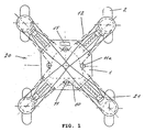
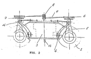
- Referring now to
Figures 1 and2 , there is illustrated a preferred embodiment of thepresent travelling device 20 comprising aframe 1 on which amotor unit 3 is arranged.Driving shaft 13 on saidmotor unit 3 is positioned, for example, vertically. One end of this drivingshaft 13 is designed for connecting a working device, for example, rotary mower, cultivation device, etc. The second end of saiddriving shaft 13 is provided with a run-up device 8, for example, driving pulleys, etc. - Moving off of said run-up
device 20 is provided, for example, by a centrifugal clutch, which connects said drivingshaft 13 with the respective transmission for driving saidtravelling wheels 2 depending onmotor unit 3 speed. - Four travelling units 21, which can have individually adjustable height, are flexibly arranged on said
frame 1 in a swinging manner. Each travelling unit 21 comprises atravelling wheel 2 turnably mounted in adevice 5 fortravelling wheel 2 mounting, which can be, for example, forked frame, so that saidtravelling wheel 2 can rotate on its horizontal axis. Travellingwheel 2 mounted in this manner is suspended on theframe 1 by means of a device 4 for travellingwheel 2 suspension, which can be, for example, leaf springs. - Each
travelling wheel 2 is also turnable on its vertical axis, and especially in an unlimited angular range of 360°. Each travelling unit 21 is provided with asecond transmission disc 6 fortravelling wheel 2 drive and with afirst transmission disc 7 fortravelling wheel 2 turning. Thesetransmission discs wheel 2.Transmission discs - Each
second transmission disc 6 for travellingwheel 2 drive is connected with said travellingwheel 2 by means of atransmission device 14. Eachsecond transmission disc 6 for travellingwheel 2 drive is further connected by means of a transmission member 9 for travellingwheel 2 drive with a run-up device 8 arranged on a drivingshaft 13 of themotor unit 3. - Each
second transmission disc 6 for travellingwheel 2 drive or directly said travellingwheel 2 can be also connected with the run-up device 8 on the drivingshaft 13 by means of another suitable transmission, such as mechanical, electric, electromagnetic or hydraulic transmission, as e.g. change gearbox, Cardan shaft, hydraulic system, etc. - All
first transmission discs 7 for travellingwheel 2 turning are connected with atransmission member 12 for travellingwheels 2 turning, guided, for example, over a drivingroller 11, and possibly over the furtherauxiliary guide rollers 11a arranged on theframe 1. - Each
first transmission disc 7 for travellingwheel 2 turning or directly the vertical shaft of travellingwheels 2 can be alternatively connected with the drivingroller 11 or directly with thesteering servomotor 10 for travellingwheels 2 turning by means of another suitable transmission, such as mechanical, electric, electromagnetic or hydraulic transmission, as e.g. change gearbox, Cardan shaft, hydraulic system, gears, etc. - Said
transmission members 9 and 12 can comprise e.g. endless belts, chains, ropes, cables, indented belts, gears, Cardan shafts, etc. - On the
frame 1 of the travellingdevice 20 there is further arranged acontrol unit 22 as well as a drivingservomotor 15 and asteering servomotor 10 for travellingwheels 2 turning, which servomotors 15 and 10 are connected with saidcontrol unit 22. Theseservomotors - Said steering
servomotor 10 and said drivingservomotor 15 can be alternatively replaced by another suitable driving devices, such as hydraulic motors, electric motors with appropriate mechanical, electric, electromagnetic or hydraulic coupling for travellingwheels 2 steering and driving. - The driving
roller 11 is connected with thesteering servomotor 10 for travellingwheels 2 turning. Said drivingroller 11 is adapted to provide by means of thetransmission member 12 for travellingwheels 2 turning the respective rotation of thetransmission discs 7 for travellingwheel 2 turning, so that the turning of all the travellingwheels 2 can be controlled simultaneously. - The steering
servomotor 10 for travellingwheels 2 turning can be alternatively replaced by another suitable driving device connected by means of suitable coupling, e.g. mechanical, electric, electromagnetic or hydraulic coupling, with the drivingroller 11 or directly with the vertical shaft of the travellingwheels 2. By means of said coupling the travellingwheels 2 turning can be provided. All the travellingwheels 2 can be turned simultaneously. - Alternatively, each of the travelling
wheels 2 can be turned also individually. - Conveniently, the
control unit 22 can be provided with a remote control so that the whole operation of the present travellingdevice 20 can be remote-controlled by means of a transmitter 23 (seeFigure 3 ). - Accordingly, the operational principle of the above described preferred embodiment consists particularly in the fact that driving of all the travelling
wheels 2 is provided simultaneously by means of transmission of a torsional moment from the drivingshaft 13 of themotor unit 3 through the run-up device 8 by means of the transmission members 9 for travellingwheel 2 drive to thesecond transmission discs 6 for travellingwheel 2 drive, and from here through thetransverse transmission devices 14 to the travellingwheels 2. - Control of the travelling
device 20 movement direction including reverse running is provided in such manner that thesteering servomotor 10 for travellingwheels 2 turning controls the drivingroller 11, and from here the torsional moment is transmitted by means of thetransmission member 12 for travellingwheels 2 turning to thefirst transmission discs 7 for travelingwheels 2 turning connected with the travellingwheels 2. Consequently, all the travellingwheels 2 are rotated simultaneously on their vertical axes in an unlimited angular range of 360°. - Conveniently, the operation of the travelling
device 20 according to the present invention is remote-controlled by means of thetransmitter 23. Saidtransmitter 23 controls thecontrol unit 22 which further controls theservomotors 10 and 15 (seeFigure 3 ). - By means of said
transmitter 23 it is possible to control, for example, starting, switching and breaking of themotor unit 3, and to control its number of revolutions. Similarly it is possible to control switching on and off of the working device, as well as travelling of the present machine and turning of the travellingwheels 2. - If the remote control is not used, then the
frame 1 can be provided with a seat and a control panel for an operator (not shown). - The travelling
device 20 according to the present invention provides a plurality of advantages in comparison with the prior art devices. - With the travelling
device 20 according to the present invention it is possible to control the direction of its movement very easily by means of simultaneous turning of all the travellingwheels 2 on their vertical axes by means of thesteering servomotor 10 for travellingwheels 2 turning. Therefore, no differential gear is needed. - By turning of the travelling
wheels 2 the present travellingdevice 20 can move to the right and to the left, wherein by turning of the travellingwheels 2 by 180° the return running can be achieved without reverse gear shifting. - No change of the centre of gravity takes place in the course of turning of the travelling
device 20, so that the turningdevice 20 cannot be overturned. The travellingwheels 2 are turnable in an unlimited angular range of 360°. - The travelling
device 20 according to the present invention provides high speed in working the terrain, so that it can replace several workers working with usual mowers or hedge cutters. Therefore, a working efficiency is improved and a labour force is saved. - The travelling
device 20 according to the present invention has also excellent self-extrication capability, because in a case of getting stuck it can be released easily by turning of the travellingwheels 2. - Utilization of the remote control can eliminate the fear feeling of the operator who can otherwise be afraid of possible fall or overturn, and particularly during the work on the slopes.
- Furthermore, the operator using the remote control is not burdened with vibrations, so that he can work for a long time without suffering from fatigue.
- Low weight of the whole travelling
device 20 enables also easily work on terrain areas accessible only with difficulties, such as e.g. waterlogged terrains, swamps, sandy surfaces, etc. - The travelling device particularly for self-propelled mower is applicable e.g for cutting or mowing of grassy or bushy areas, for maintenance the roadsides, railway tracks, riverbanks, etc., as well as for working all the flat or slanted areas accessible only with difficulties.
-
- 1 -
- frame
- 2 -
- travelling wheel
- 3 -
- motor unit
- 4 -
- device 4 for travelling
wheel 2 suspension - 5 -
-
device 5 for travellingwheel 2 mounting - 6 -
-
second transmission disc 6 for travellingwheel 2 drive - 7 -
-
first transmission disc 7 for travellingwheel 2 turning - 8 -
- run-up device
- 9 -
- transmission member 9 for travelling
wheel 2 drive - 10 -
- steering
servomotor 10 for travellingwheel 2 turning - 11 -
- driving roller
- 11a -
- auxiliary guide roller
- 12 -
-
transmission member 12 for travellingwheel 2 turning - 13 -
- drive shaft
- 14 -
- transmission device
- 15 -
- driving servomotor
- 20 -
- travelling device
- 21 -
- travelling unit
- 22 -
- control unit
- 23 -
- transmitter
Claims (11)
- Travelling device (20) particulary for self-propelled mower, said travelling device (20) comprises a frame (1), provided with several identical travelling units (21) arranged on its circumference, each travelling unit (21) comprises a flexibly suspended travelling wheel (2) rotating both on its horizontal and vertical axes in an unlimited angular range of 360°, each travelling unit (21) comprising a first transmission disc (7) for travelling wheel (2) turning with a transmission member (12), wherein said frame (1) is further provided with a working device and a motor unit (3) with a driving shaft (13) for said working device and said travelling wheels (2), characterized in that for travelling wheel (2) drive each travelling unit (21) further comprises a second transmission disc (6) connected with each wheel (2) by a transmission device (14), wherein all said second discs (6) are connected with run-up device (8) on drive shaft (13) by means of transmission members (9).
- Travelling device (20) according to claim 1, wherein each second transmission disc (6) for travelling wheel (2) drive is positioned horizontally and is turnable on its vertical axis.
- Travelling device (20) according to claim 1, wherein each first transmission disc (7) for travelling wheel (2) turning is positioned horizontally and is turnable on its vertical axis.
- Travelling device (20) according to any of claims 1 to 3, wherein said transmission member (9) for travelling wheel (2) drive comprises an endless flexible member.
- Travelling device (20) according to any of claims 1 to 3, wherein said transmission member (9) for travelling wheel (2) turning comprises gears.
- Travelling device (20) according to any of claims 1 to 3, wherein said transmission member (9) for travelling wheel (2) drive comprises Cardan shafts.
- Travelling device (20) according to any of claims 1 to 6, wherein a control unit (22) interconnected with driving servomotor (15) and steering servomotor (10) for travelling wheels (2) turning is further arranged on said frame (1).
- Travelling device (20) according to claim 7, wherein said control unit (22) is remote-controlled.
- Travelling device (20) according to claim 8, wherein said control unit (22) is remote-controlled by means of transmitter (23) for transmitting radio signals or optical signals.
- Travelling device (20) according to any of claims 1 to 7, wherein a seat and a control panel are arranged on said frame (1).
- Travelling device (20) according to any of claims 1 to 10, wherein said travelling wheels (2) are particularly four.
Applications Claiming Priority (3)
| Application Number | Priority Date | Filing Date | Title |
|---|---|---|---|
| CZ20022755 | 2002-08-13 | ||
| CZ20022755A CZ292880B6 (en) | 2002-08-13 | 2002-08-13 | Driving mechanism, particularly of a self-propelled harvesting machine |
| PCT/CZ2003/000045 WO2004014119A1 (en) | 2002-08-13 | 2003-08-11 | Travelling device particularly for self-propelled mower |
Publications (2)
| Publication Number | Publication Date |
|---|---|
| EP1538889A1 EP1538889A1 (en) | 2005-06-15 |
| EP1538889B1 true EP1538889B1 (en) | 2008-09-17 |
Family
ID=29591591
Family Applications (1)
| Application Number | Title | Priority Date | Filing Date |
|---|---|---|---|
| EP03783909A Expired - Lifetime EP1538889B1 (en) | 2002-08-13 | 2003-08-11 | Travelling device particularly for self-propelled mower |
Country Status (10)
| Country | Link |
|---|---|
| US (1) | US7416040B2 (en) |
| EP (1) | EP1538889B1 (en) |
| JP (1) | JP4370248B2 (en) |
| AT (1) | ATE408334T1 (en) |
| AU (1) | AU2003254604A1 (en) |
| CZ (1) | CZ292880B6 (en) |
| DE (1) | DE60323646D1 (en) |
| DK (1) | DK1538889T3 (en) |
| ES (1) | ES2314265T3 (en) |
| WO (1) | WO2004014119A1 (en) |
Families Citing this family (23)
| Publication number | Priority date | Publication date | Assignee | Title |
|---|---|---|---|---|
| US7024842B2 (en) * | 2003-11-21 | 2006-04-11 | Deere & Company | Self-propelled mower having enhanced maneuverability |
| US7024843B2 (en) | 2003-11-21 | 2006-04-11 | Deere & Company | Self-propelled mower having enhanced maneuverability |
| DE202006010790U1 (en) * | 2006-05-29 | 2006-09-21 | Zappel, Wolfgang | Shunting vehicle for road and rail applications with pneumatic tires to run on the rails ore road and with retracting guides to align with the edges of the rails |
| US8794288B2 (en) * | 2008-08-21 | 2014-08-05 | Vmi Holland B.V. | Method for transferring and placing beads for tyres, device for carrying out such a method and spacer to be used in such a method and/or device |
| CZ300335B6 (en) * | 2008-11-28 | 2009-04-22 | DVORÁK - svahové sekacky s.r.o. | Hydraulic stabilization capstan |
| PL2814312T3 (en) * | 2012-02-13 | 2020-06-29 | Husqvarna Ab | All wheel drive, walk behind mower |
| RU2512055C2 (en) * | 2012-07-17 | 2014-04-10 | Айбулат Кашафетдинович Амирханов | All-purpose super mobile and super-flotation vehicle |
| RU2510348C1 (en) * | 2012-07-17 | 2014-03-27 | Айбулат Кашафетдинович Амирханов | Super mobile and superhigh cross-country capacity universal vehicle |
| JP2014103878A (en) * | 2012-11-27 | 2014-06-09 | Chikusui Canycom Inc | Traveling device for automatic work |
| KR101762479B1 (en) * | 2014-03-10 | 2017-07-27 | 가부시끼 가이샤 구보다 | Mower |
| US9864396B1 (en) * | 2014-08-05 | 2018-01-09 | Hydro-Gear Limited Partnership | Highly maneuverable mowing vehicle with Mecanum wheels |
| US9677648B2 (en) | 2015-01-14 | 2017-06-13 | The Toro Company | Walk-behind power equipment unit having all-wheel drive control system |
| US10039229B2 (en) * | 2016-06-28 | 2018-08-07 | The Toro Company | Walk power mower having forward and reverse traction drive |
| US10111381B2 (en) | 2016-06-28 | 2018-10-30 | The Toro Company | Walk power mower with transmission providing both forward and reverse propulsion |
| CA3037676A1 (en) | 2016-09-21 | 2018-03-29 | Mtd Products Inc | Control assembly for a walk-behind mower |
| FR3069812A1 (en) * | 2017-08-01 | 2019-02-08 | France Reducteurs | ROLLER |
| DE102019113399A1 (en) | 2018-11-02 | 2020-05-07 | Ralf Hintersatz | Chassis with all-wheel steering |
| CN109649681A (en) * | 2018-12-26 | 2019-04-19 | 成都航空职业技术学院 | A kind of mobile helicopter repair working auxiliary device convenient for adjusting |
| CN111619654A (en) * | 2019-02-27 | 2020-09-04 | 河海大学常州校区 | Obstacle avoidance robot |
| DE202020101919U1 (en) | 2020-04-07 | 2020-06-16 | Logistic Production Gmbh | Chassis with all-wheel steering |
| US20220151145A1 (en) * | 2020-10-08 | 2022-05-19 | Mdb Srl | Radio-controlled vehicle |
| CN114379645B (en) * | 2022-03-24 | 2022-05-31 | 济南科亚电子科技有限公司 | Dispersible high-load AGV double-steering-wheel system |
| CN115234765B (en) * | 2022-07-07 | 2024-04-19 | 中国地质大学(武汉) | Computer vibration/noise reduction device convenient to disassemble and assemble |
Family Cites Families (12)
| Publication number | Priority date | Publication date | Assignee | Title |
|---|---|---|---|---|
| US2698507A (en) * | 1952-12-30 | 1955-01-04 | Barton G Siebring | Remote control lawn mower |
| US3203500A (en) * | 1962-10-22 | 1965-08-31 | Howard A Gaberson | Area covering devices |
| US3839610A (en) * | 1972-09-01 | 1974-10-01 | H Harlow | Steering mechanism for riding mower |
| US4041678A (en) * | 1975-09-08 | 1977-08-16 | Ray Owen Chaney | Short turn vehicle |
| US4318266A (en) | 1980-12-15 | 1982-03-09 | Max Taube | Remotely controlled self-propelled power lawn mower |
| US4964265A (en) * | 1989-09-11 | 1990-10-23 | Young Carl W | Remotely controlled lawn mower |
| US5090185A (en) * | 1991-02-11 | 1992-02-25 | Meeks Earl L | Mower |
| US5323593A (en) * | 1993-01-13 | 1994-06-28 | Cline Lohn G | Method and apparatus for mowing lawns |
| DE4303342A1 (en) | 1993-02-05 | 1994-08-11 | Baumann R & Co | Steering device for a vehicle |
| GB9423669D0 (en) * | 1994-11-23 | 1995-01-11 | Dowler David | A vehicle |
| US5667032A (en) * | 1994-12-22 | 1997-09-16 | Kamlukin; Igor | Self propelled mower with low radius pivoted rear wheel steering |
| US5974347A (en) * | 1997-03-14 | 1999-10-26 | Nelson; Russell G. | Automated lawn mower |
-
2002
- 2002-08-13 CZ CZ20022755A patent/CZ292880B6/en not_active IP Right Cessation
-
2003
- 2003-08-11 DE DE60323646T patent/DE60323646D1/en not_active Expired - Lifetime
- 2003-08-11 AU AU2003254604A patent/AU2003254604A1/en not_active Abandoned
- 2003-08-11 US US10/523,451 patent/US7416040B2/en active Active
- 2003-08-11 EP EP03783909A patent/EP1538889B1/en not_active Expired - Lifetime
- 2003-08-11 AT AT03783909T patent/ATE408334T1/en active
- 2003-08-11 ES ES03783909T patent/ES2314265T3/en not_active Expired - Lifetime
- 2003-08-11 WO PCT/CZ2003/000045 patent/WO2004014119A1/en active IP Right Grant
- 2003-08-11 DK DK03783909T patent/DK1538889T3/en active
- 2003-08-11 JP JP2004526593A patent/JP4370248B2/en not_active Expired - Lifetime
Also Published As
| Publication number | Publication date |
|---|---|
| JP4370248B2 (en) | 2009-11-25 |
| ES2314265T3 (en) | 2009-03-16 |
| DK1538889T3 (en) | 2009-01-19 |
| DE60323646D1 (en) | 2008-10-30 |
| ATE408334T1 (en) | 2008-10-15 |
| CZ20022755A3 (en) | 2003-12-17 |
| US7416040B2 (en) | 2008-08-26 |
| WO2004014119A1 (en) | 2004-02-19 |
| JP2005535320A (en) | 2005-11-24 |
| AU2003254604A1 (en) | 2004-02-25 |
| CZ292880B6 (en) | 2003-12-17 |
| EP1538889A1 (en) | 2005-06-15 |
| US20060102410A1 (en) | 2006-05-18 |
Similar Documents
| Publication | Publication Date | Title |
|---|---|---|
| EP1538889B1 (en) | Travelling device particularly for self-propelled mower | |
| US5816034A (en) | Belt design for mower | |
| US4535859A (en) | Vehicle | |
| US6629577B1 (en) | Driving apparatus for speed changing and steering of a vehicle | |
| US4879867A (en) | Self-propelled mower with hydrostatic drive | |
| EP0349015B1 (en) | A mowing machine | |
| EP0068560A2 (en) | Mowing device | |
| US4620599A (en) | Ground working machine for hoeing, tilling and the like | |
| EP1100711B1 (en) | Driving apparatus for speed changing and steering of a vehicle | |
| CN114633619B (en) | Self-driven vehicle | |
| KR102573116B1 (en) | working machine | |
| JPH0513144Y2 (en) | ||
| CN209710626U (en) | Miniature rotary cultivator | |
| CN109197114B (en) | Self-propelled chassis liftable mower | |
| US6699147B1 (en) | Mower with dual mechanical transmissions | |
| CN109328616B (en) | Self-propelled mower | |
| CN218702712U (en) | Four-wheel riding type miniature tillage equipment | |
| JP2923245B2 (en) | Transplant machine | |
| CN220674316U (en) | Portable rotary cultivator | |
| RU2220856C2 (en) | Agricultural machine wheeled power gear | |
| EP3981241A1 (en) | Radio-controlled vehicle | |
| SU1261574A1 (en) | Machine for digging out young plants | |
| EP1068789A2 (en) | Lawnmower with wide field of action | |
| JPH0516839A (en) | Four-wheel type riding farm working controller | |
| JPH09202255A (en) | Steering device of running work machine |
Legal Events
| Date | Code | Title | Description |
|---|---|---|---|
| PUAI | Public reference made under article 153(3) epc to a published international application that has entered the european phase |
Free format text: ORIGINAL CODE: 0009012 |
|
| 17P | Request for examination filed |
Effective date: 20050302 |
|
| AK | Designated contracting states |
Kind code of ref document: A1 Designated state(s): AT BE BG CH CY CZ DE DK EE ES FI FR GB GR HU IE IT LI LU MC NL PT RO SE SI SK TR |
|
| AX | Request for extension of the european patent |
Extension state: AL LT LV MK |
|
| DAX | Request for extension of the european patent (deleted) | ||
| REG | Reference to a national code |
Ref country code: HK Ref legal event code: DE Ref document number: 1082377 Country of ref document: HK |
|
| 17Q | First examination report despatched |
Effective date: 20070604 |
|
| GRAP | Despatch of communication of intention to grant a patent |
Free format text: ORIGINAL CODE: EPIDOSNIGR1 |
|
| GRAS | Grant fee paid |
Free format text: ORIGINAL CODE: EPIDOSNIGR3 |
|
| RAP1 | Party data changed (applicant data changed or rights of an application transferred) |
Owner name: DVORAK - SVAHOVE SEKACKY S.R.O. |
|
| RIN1 | Information on inventor provided before grant (corrected) |
Inventor name: LUBOMIR DVORAK |
|
| GRAA | (expected) grant |
Free format text: ORIGINAL CODE: 0009210 |
|
| AK | Designated contracting states |
Kind code of ref document: B1 Designated state(s): AT BE BG CH CY CZ DE DK EE ES FI FR GB GR HU IE IT LI LU MC NL PT RO SE SI SK TR |
|
| REG | Reference to a national code |
Ref country code: GB Ref legal event code: FG4D |
|
| REG | Reference to a national code |
Ref country code: CH Ref legal event code: EP |
|
| REG | Reference to a national code |
Ref country code: IE Ref legal event code: FG4D |
|
| REF | Corresponds to: |
Ref document number: 60323646 Country of ref document: DE Date of ref document: 20081030 Kind code of ref document: P |
|
| REG | Reference to a national code |
Ref country code: RO Ref legal event code: EPE |
|
| REG | Reference to a national code |
Ref country code: SE Ref legal event code: TRGR |
|
| REG | Reference to a national code |
Ref country code: CH Ref legal event code: NV Representative=s name: ARNOLD & SIEDSMA AG |
|
| REG | Reference to a national code |
Ref country code: DK Ref legal event code: T3 |
|
| PG25 | Lapsed in a contracting state [announced via postgrant information from national office to epo] |
Ref country code: SI Free format text: LAPSE BECAUSE OF FAILURE TO SUBMIT A TRANSLATION OF THE DESCRIPTION OR TO PAY THE FEE WITHIN THE PRESCRIBED TIME-LIMIT Effective date: 20080917 |
|
| REG | Reference to a national code |
Ref country code: ES Ref legal event code: FG2A Ref document number: 2314265 Country of ref document: ES Kind code of ref document: T3 |
|
| PG25 | Lapsed in a contracting state [announced via postgrant information from national office to epo] |
Ref country code: BE Free format text: LAPSE BECAUSE OF FAILURE TO SUBMIT A TRANSLATION OF THE DESCRIPTION OR TO PAY THE FEE WITHIN THE PRESCRIBED TIME-LIMIT Effective date: 20080917 |
|
| REG | Reference to a national code |
Ref country code: HU Ref legal event code: AG4A Ref document number: E004735 Country of ref document: HU |
|
| PG25 | Lapsed in a contracting state [announced via postgrant information from national office to epo] |
Ref country code: PT Free format text: LAPSE BECAUSE OF FAILURE TO SUBMIT A TRANSLATION OF THE DESCRIPTION OR TO PAY THE FEE WITHIN THE PRESCRIBED TIME-LIMIT Effective date: 20090217 |
|
| REG | Reference to a national code |
Ref country code: HK Ref legal event code: WD Ref document number: 1082377 Country of ref document: HK |
|
| PLBE | No opposition filed within time limit |
Free format text: ORIGINAL CODE: 0009261 |
|
| STAA | Information on the status of an ep patent application or granted ep patent |
Free format text: STATUS: NO OPPOSITION FILED WITHIN TIME LIMIT |
|
| PG25 | Lapsed in a contracting state [announced via postgrant information from national office to epo] |
Ref country code: EE Free format text: LAPSE BECAUSE OF FAILURE TO SUBMIT A TRANSLATION OF THE DESCRIPTION OR TO PAY THE FEE WITHIN THE PRESCRIBED TIME-LIMIT Effective date: 20080917 |
|
| 26N | No opposition filed |
Effective date: 20090618 |
|
| PG25 | Lapsed in a contracting state [announced via postgrant information from national office to epo] |
Ref country code: MC Free format text: LAPSE BECAUSE OF NON-PAYMENT OF DUE FEES Effective date: 20090831 |
|
| REG | Reference to a national code |
Ref country code: IE Ref legal event code: MM4A |
|
| PG25 | Lapsed in a contracting state [announced via postgrant information from national office to epo] |
Ref country code: IE Free format text: LAPSE BECAUSE OF NON-PAYMENT OF DUE FEES Effective date: 20090811 |
|
| PGFP | Annual fee paid to national office [announced via postgrant information from national office to epo] |
Ref country code: SK Payment date: 20100528 Year of fee payment: 8 |
|
| PG25 | Lapsed in a contracting state [announced via postgrant information from national office to epo] |
Ref country code: GR Free format text: LAPSE BECAUSE OF FAILURE TO SUBMIT A TRANSLATION OF THE DESCRIPTION OR TO PAY THE FEE WITHIN THE PRESCRIBED TIME-LIMIT Effective date: 20081218 |
|
| PGFP | Annual fee paid to national office [announced via postgrant information from national office to epo] |
Ref country code: RO Payment date: 20100806 Year of fee payment: 8 |
|
| PGFP | Annual fee paid to national office [announced via postgrant information from national office to epo] |
Ref country code: FI Payment date: 20100820 Year of fee payment: 8 Ref country code: BG Payment date: 20100809 Year of fee payment: 8 |
|
| PG25 | Lapsed in a contracting state [announced via postgrant information from national office to epo] |
Ref country code: LU Free format text: LAPSE BECAUSE OF NON-PAYMENT OF DUE FEES Effective date: 20090811 |
|
| PG25 | Lapsed in a contracting state [announced via postgrant information from national office to epo] |
Ref country code: TR Free format text: LAPSE BECAUSE OF FAILURE TO SUBMIT A TRANSLATION OF THE DESCRIPTION OR TO PAY THE FEE WITHIN THE PRESCRIBED TIME-LIMIT Effective date: 20080917 |
|
| PG25 | Lapsed in a contracting state [announced via postgrant information from national office to epo] |
Ref country code: CY Free format text: LAPSE BECAUSE OF FAILURE TO SUBMIT A TRANSLATION OF THE DESCRIPTION OR TO PAY THE FEE WITHIN THE PRESCRIBED TIME-LIMIT Effective date: 20080917 |
|
| PG25 | Lapsed in a contracting state [announced via postgrant information from national office to epo] |
Ref country code: SK Free format text: LAPSE BECAUSE OF NON-PAYMENT OF DUE FEES Effective date: 20110811 |
|
| REG | Reference to a national code |
Ref country code: SK Ref legal event code: MM4A Ref document number: E 4697 Country of ref document: SK Effective date: 20110811 |
|
| PG25 | Lapsed in a contracting state [announced via postgrant information from national office to epo] |
Ref country code: FI Free format text: LAPSE BECAUSE OF NON-PAYMENT OF DUE FEES Effective date: 20110811 |
|
| PG25 | Lapsed in a contracting state [announced via postgrant information from national office to epo] |
Ref country code: RO Free format text: LAPSE BECAUSE OF NON-PAYMENT OF DUE FEES Effective date: 20110811 |
|
| PGFP | Annual fee paid to national office [announced via postgrant information from national office to epo] |
Ref country code: HU Payment date: 20120529 Year of fee payment: 10 Ref country code: ES Payment date: 20120807 Year of fee payment: 10 |
|
| PG25 | Lapsed in a contracting state [announced via postgrant information from national office to epo] |
Ref country code: BG Free format text: LAPSE BECAUSE OF NON-PAYMENT OF DUE FEES Effective date: 20120630 |
|
| PG25 | Lapsed in a contracting state [announced via postgrant information from national office to epo] |
Ref country code: HU Free format text: LAPSE BECAUSE OF NON-PAYMENT OF DUE FEES Effective date: 20130812 |
|
| REG | Reference to a national code |
Ref country code: ES Ref legal event code: FD2A Effective date: 20150709 |
|
| PG25 | Lapsed in a contracting state [announced via postgrant information from national office to epo] |
Ref country code: ES Free format text: LAPSE BECAUSE OF NON-PAYMENT OF DUE FEES Effective date: 20130812 |
|
| REG | Reference to a national code |
Ref country code: FR Ref legal event code: PLFP Year of fee payment: 14 |
|
| REG | Reference to a national code |
Ref country code: FR Ref legal event code: PLFP Year of fee payment: 15 |
|
| REG | Reference to a national code |
Ref country code: FR Ref legal event code: PLFP Year of fee payment: 16 |
|
| PGFP | Annual fee paid to national office [announced via postgrant information from national office to epo] |
Ref country code: GB Payment date: 20220623 Year of fee payment: 20 Ref country code: FR Payment date: 20220520 Year of fee payment: 20 Ref country code: CZ Payment date: 20220615 Year of fee payment: 20 |
|
| PGFP | Annual fee paid to national office [announced via postgrant information from national office to epo] |
Ref country code: NL Payment date: 20220826 Year of fee payment: 20 |
|
| PGFP | Annual fee paid to national office [announced via postgrant information from national office to epo] |
Ref country code: SE Payment date: 20220714 Year of fee payment: 20 Ref country code: IT Payment date: 20220802 Year of fee payment: 20 Ref country code: DK Payment date: 20220715 Year of fee payment: 20 Ref country code: DE Payment date: 20220615 Year of fee payment: 20 Ref country code: AT Payment date: 20220825 Year of fee payment: 20 |
|
| PGFP | Annual fee paid to national office [announced via postgrant information from national office to epo] |
Ref country code: CH Payment date: 20220905 Year of fee payment: 20 |
|
| REG | Reference to a national code |
Ref country code: DE Ref legal event code: R071 Ref document number: 60323646 Country of ref document: DE |
|
| REG | Reference to a national code |
Ref country code: DK Ref legal event code: EUP Expiry date: 20230811 |
|
| REG | Reference to a national code |
Ref country code: CH Ref legal event code: PL |
|
| REG | Reference to a national code |
Ref country code: NL Ref legal event code: MK Effective date: 20230810 |
|
| REG | Reference to a national code |
Ref country code: GB Ref legal event code: PE20 Expiry date: 20230810 |
|
| REG | Reference to a national code |
Ref country code: SE Ref legal event code: EUG |
|
| REG | Reference to a national code |
Ref country code: AT Ref legal event code: MK07 Ref document number: 408334 Country of ref document: AT Kind code of ref document: T Effective date: 20230811 |
|
| PG25 | Lapsed in a contracting state [announced via postgrant information from national office to epo] |
Ref country code: GB Free format text: LAPSE BECAUSE OF EXPIRATION OF PROTECTION Effective date: 20230810 Ref country code: CZ Free format text: LAPSE BECAUSE OF EXPIRATION OF PROTECTION Effective date: 20230811 |