EP1538719A2 - Anschlussmodul für die Unterflurverkabelung von Telekommunikations- bzw. Datenleitungen - Google Patents
Anschlussmodul für die Unterflurverkabelung von Telekommunikations- bzw. Datenleitungen Download PDFInfo
- Publication number
- EP1538719A2 EP1538719A2 EP04026662A EP04026662A EP1538719A2 EP 1538719 A2 EP1538719 A2 EP 1538719A2 EP 04026662 A EP04026662 A EP 04026662A EP 04026662 A EP04026662 A EP 04026662A EP 1538719 A2 EP1538719 A2 EP 1538719A2
- Authority
- EP
- European Patent Office
- Prior art keywords
- front surface
- connection module
- sockets
- feature
- telecommunications
- Prior art date
- Legal status (The legal status is an assumption and is not a legal conclusion. Google has not performed a legal analysis and makes no representation as to the accuracy of the status listed.)
- Withdrawn
Links
Images



Classifications
-
- H—ELECTRICITY
- H02—GENERATION; CONVERSION OR DISTRIBUTION OF ELECTRIC POWER
- H02G—INSTALLATION OF ELECTRIC CABLES OR LINES, OR OF COMBINED OPTICAL AND ELECTRIC CABLES OR LINES
- H02G3/00—Installations of electric cables or lines or protective tubing therefor in or on buildings, equivalent structures or vehicles
- H02G3/02—Details
- H02G3/08—Distribution boxes; Connection or junction boxes
- H02G3/18—Distribution boxes; Connection or junction boxes providing line outlets
- H02G3/185—Floor outlets and access cups
-
- H—ELECTRICITY
- H02—GENERATION; CONVERSION OR DISTRIBUTION OF ELECTRIC POWER
- H02G—INSTALLATION OF ELECTRIC CABLES OR LINES, OR OF COMBINED OPTICAL AND ELECTRIC CABLES OR LINES
- H02G3/00—Installations of electric cables or lines or protective tubing therefor in or on buildings, equivalent structures or vehicles
- H02G3/36—Installations of cables or lines in walls, floors or ceilings
Definitions
- the invention relates to connection modules for underfloor cabling Telecommunication or data lines according to the preamble of the claim 1.
- the shell is first created, consisting of walls, ceilings and floors. Then follows the interior. These include installation work for heating, water, electrical, etc. Part the supply lines is laid on the bare floor before floor insulation and screed are introduced. Especially for office buildings with raised floor there are Underfloor installation systems installed in raised floors. At certain Positions are used in double floor connection boxes, which are puncture proof Flap can be closed. Behind the flap are sockets, Fuses etc. housed protected. This installation system allows to place the connection boxes within the floor grid arbitrarily, because the Cables and wires are laid completely freely in the intermediate floor.
- EP 1 191 656 A is a further device receptacle for a Underfloor box known.
- the device holder has a frame-shaped circumferential wall with guides and a mounting frame for Inclined installation of connectors.
- Above the connectors are a hood with a Recess and a support provided with guides, wherein the Mounting frame in a recess at least partially covering Way is attachable to the hood.
- the hood is in the guides of the wearer retractable and lockable with this.
- a disadvantage of these underfloor connection devices for telecommunications and Data lines is the multitude of individual elements that make up them are composed.
- a far greater disadvantage of all commercial Underfloor connection modules is due to the fact that the connection of the Cable ends to the respective sockets only performed by a specialist may be. Also, the connection of the cable ends is even despite use prefabricated connection parts and despite the use of special tools time consuming and error prone. That is unsatisfactory.
- connection modules of specify the type mentioned the much easier and faster assembled and, above all, can be connected by auxiliary staff.
- the main advantage of the present invention is the low time required for the assembly and the possibility to perform the installation of auxiliary staff too to let.
- data sockets are used, which are from behind to the front surface of the connection module to be inserted into the underfloor tank snap into place.
- Data outlets are also used Data outlets. This allows the underfloor wiring be carried out by means of prefabricated lines that the Installation staff only need to be infected. prefabricated Telecommunication and data lines are factory tested. Stripping and Contact on site and resulting assembly errors are completely different out.
- Another advantage of the present invention is that the used Sockets are encapsulated and insulated on all sides. Measures for an additional Insulation in the form of aprons and the like, as in the prior art can be used, can be omitted.
- the front surface has prepared Cutouts for the telecommunications or data outlets. These are only open when needed.
- the front sockets are at an angle of approx. 45 degrees to the front surface. This combines a good space utilization with a good one Accessibility.
- the rear sockets are at an angle of about 30 Degree to the front surface. This also combines an even smaller footprint with still sufficient accessibility during installation.
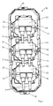
- Fig. 1 as a view of the front and Fig. 2 as a view of the back show a Connection module 10 for the underground wiring of telecommunications or Data lines 1, 2.
- a Connection module 10 for the underground wiring of telecommunications or Data lines 1, 2.
- the front surface 11 has three sections, in the back of each of a telecommunications or Data socket 20 is inserted.
- the front surface 11 has on its back appropriate Retaining pins 13, with the corresponding holding devices 22 to the sockets 20th cooperate.
- the sockets 20 of the present embodiment each have two Front sockets, in each of which a telecommunication or Data line 1 with factory-assembled connector plugged can.
- the unused sockets are closed by a flap 21.
- sockets 20 and the back by telecommunications or data lines 2 are contacted with pre-assembled plugs.
- each Data socket 20 is equipped with two conventional cable connections 24, which are parallel to the front surface 11 in the present example.
- each Data socket 20 is equipped with three standard cable connections (25), which are in the present example at an angle of about 30 degrees to the front surface 11.
Landscapes
- Engineering & Computer Science (AREA)
- Architecture (AREA)
- Civil Engineering (AREA)
- Structural Engineering (AREA)
- Installation Of Indoor Wiring (AREA)
- Structure Of Telephone Exchanges (AREA)
Abstract
Description
- Fig. 1
- die Vorderseite eines Anschlussmoduls für die Unterflur-Verkabelung von Telekommunikations- bzw. Datenleitungen,
- Fig. 2
- die Rückseite des Anschlussmoduls der Fig. 1,
- Fig. 3
- die Rückseite eines weiteren Anschlussmoduls und
- Fig. 4
- die Rückseite eines dritten Anschlussmoduls.
Claims (7)
- Anschlussmodul (10) für die Unterflur-Verkabelung von Telekommunikations- bzw. Datenleitungen (1, 2), im wesentlichen umfassendgekennzeichnet durch die Merkmale:eine etwa rechteckige Frontfläche (11),Rasthaken (12) an den Stirnseiten der Frontfläche (11) zur höhenverstellbaren Befestigung in einer Unterflur-Gerätedose,und wenigstens eine Telekommunikations- bzw. Datensteckdose (20), aufgerastet auf die Frontfläche (11, 12),die Frontfläche (11) besitzt vorbereitete Ausschnitte für die Steckdosen (20),die Steckdose (20) ist von hinten in die Ausschnitte der Frontfläche (11) eingerastet.
- Anschlussmodul nach Anspruch 1, gekennzeichnet durch das Merkmal:die Telekommunikations- bzw. Datensteckdose (20) besitzt auch auf ihrer Rückseite Steckbuchsen (23) zum Anstecken von konfektionierten Telekommunikations- bzw. Datenkabeln (2).
- Anschlussmodul nach einem der Ansprüche 1 oder 2, gekennzeichnet durch das Merkmal:die frontseitigen Steckbuchsen stehen in einem Winkel von ca. 45 Grad zur Frontfläche (11).
- Anschlussmodul nach einem der Ansprüche 1 bis 3, gekennzeichnet durch das Merkmal:die rückseitigen Steckbuchsen (23) stehen in einem Winkel von ca. 30 Grad zur Frontfläche (11).
- Anschlussmodul nach Anspruch 1, gekennzeichnet durch das Merkmal:die Telekommunikations- bzw. Datensteckdose (20) besitzt auf ihrer Rückseite Kabelanschlüsse (24).
- Anschlussmodul nach Anspruch 5, gekennzeichnet durch das Merkmal:die Kabelanschlüsse (24) stehen in einem Winkel von ca. 30 Grad zur Frontfläche (11).
- Anschlussmodul nach Anspruch 5 oder 6, gekennzeichnet durch das Merkmal:an der Frontfläche (11) ist eine umlaufende Schürze (13) angebracht.
Applications Claiming Priority (2)
| Application Number | Priority Date | Filing Date | Title |
|---|---|---|---|
| DE20318953U | 2003-12-06 | ||
| DE20318953U DE20318953U1 (de) | 2003-12-06 | 2003-12-06 | Anschlussmodul für die Unterflurverkabelung von Telekommunikations- bzw. Datenleitungen |
Publications (2)
| Publication Number | Publication Date |
|---|---|
| EP1538719A2 true EP1538719A2 (de) | 2005-06-08 |
| EP1538719A3 EP1538719A3 (de) | 2006-06-07 |
Family
ID=34442562
Family Applications (1)
| Application Number | Title | Priority Date | Filing Date |
|---|---|---|---|
| EP04026662A Withdrawn EP1538719A3 (de) | 2003-12-06 | 2004-11-10 | Anschlussmodul für die Unterflurverkabelung von Telekommunikations- bzw. Datenleitungen |
Country Status (3)
| Country | Link |
|---|---|
| EP (1) | EP1538719A3 (de) |
| DE (1) | DE20318953U1 (de) |
| NO (1) | NO20045183L (de) |
Family Cites Families (4)
| Publication number | Priority date | Publication date | Assignee | Title |
|---|---|---|---|---|
| US4289921A (en) * | 1979-12-26 | 1981-09-15 | H. H. Robertson Company | Electrical activating assembly and closure member therefor |
| US4297524A (en) * | 1979-12-26 | 1981-10-27 | H. H. Robertson Company | Electrical activating assembly and receptacle support means therefor |
| DE20016343U1 (de) * | 2000-09-21 | 2000-12-14 | Albert Ackermann GmbH & Co. KG, 51643 Gummersbach | Geräteaufnahme für eine Unterflurgerätedose |
| DE20204093U1 (de) * | 2002-03-13 | 2002-05-23 | RIA-BTR Produktions GmbH, 78176 Blumberg | Anschlusssystem für Unterflur-Verkabelungen |
-
2003
- 2003-12-06 DE DE20318953U patent/DE20318953U1/de not_active Expired - Lifetime
-
2004
- 2004-11-10 EP EP04026662A patent/EP1538719A3/de not_active Withdrawn
- 2004-11-26 NO NO20045183A patent/NO20045183L/no not_active Application Discontinuation
Also Published As
| Publication number | Publication date |
|---|---|
| EP1538719A3 (de) | 2006-06-07 |
| DE20318953U1 (de) | 2005-04-14 |
| NO20045183L (no) | 2005-06-07 |
Similar Documents
| Publication | Publication Date | Title |
|---|---|---|
| DE69209079T2 (de) | Stromschiene mit frei montierbarer steckdose | |
| DE69127019T2 (de) | Elektrifiziertes Wandplattensystem | |
| EP2321882B1 (de) | Serverschrank | |
| EP1785117B1 (de) | Konsole mit einem Stauraum | |
| DE4210657A1 (de) | Einschub-Niederspannungsschaltanlage zur Abgabe oder Verteilung elektrischer Energie | |
| DE102004054173B4 (de) | Niederspannungsschaltschrank | |
| DE20318953U1 (de) | Anschlussmodul für die Unterflurverkabelung von Telekommunikations- bzw. Datenleitungen | |
| DE102004022785B4 (de) | Zählerschrank zur Aufnahme wenigstens eines Stromzählers | |
| EP1538720A1 (de) | Anschlusssystem für die Unterflurverkabelung von Starkstromnetzen | |
| DE69607020T2 (de) | Kunststoffabzweigdose mit steckdosen | |
| DE9315131U1 (de) | Geräteschrank | |
| DE9003879U1 (de) | Kabelstecker-Verteiler-Kasten | |
| DE102012220951B4 (de) | Montagesystem für einen elektrischen Schaltschrank, sowie Schaltschrank | |
| DE19734584B4 (de) | Zweiteiliges Verteilergehäuse für elektrotechnische Installationen | |
| EP0495359B1 (de) | Steckdosenbox | |
| DE102005015943B4 (de) | Elektrische Schaltanlage | |
| DE102013102232A1 (de) | Unterputzkasten, insbesondere Unterputzverteilerkasten | |
| DE19745385A1 (de) | Verfahren zum Ausführen einer Elektroinstallation und Bausatz für Elektroinstallation | |
| EP1555727A2 (de) | Anschlussmodul | |
| DE102019119116A1 (de) | Anordnung zur verteilung von gasförmigen und flüssigen medien in einem labor | |
| DE2811693C2 (de) | ||
| DE19814647B4 (de) | Elektrischer Installationsgeräteträger | |
| EP0865116A1 (de) | Anschlussdose für die Telekommunikation | |
| DE102014114988A1 (de) | System mit Anschlussraum zur Installation und Verbindung von elektrischen und/oder elektronischen Geräten sowie Einrichtungen in Anschlussräumen | |
| DE4337924A1 (de) | Vorrichtung zur Erzeugung einer Vielfachanschlußmöglichkeit von datenverarbeitenden Endgeräten, insbesondere Ethernet-Hub |
Legal Events
| Date | Code | Title | Description |
|---|---|---|---|
| PUAI | Public reference made under article 153(3) epc to a published international application that has entered the european phase |
Free format text: ORIGINAL CODE: 0009012 |
|
| AK | Designated contracting states |
Kind code of ref document: A2 Designated state(s): AT BE BG CH CY CZ DE DK EE ES FI FR GB GR HU IE IS IT LI LU MC NL PL PT RO SE SI SK TR |
|
| AX | Request for extension of the european patent |
Extension state: AL HR LT LV MK YU |
|
| PUAL | Search report despatched |
Free format text: ORIGINAL CODE: 0009013 |
|
| AK | Designated contracting states |
Kind code of ref document: A3 Designated state(s): AT BE BG CH CY CZ DE DK EE ES FI FR GB GR HU IE IS IT LI LU MC NL PL PT RO SE SI SK TR |
|
| AX | Request for extension of the european patent |
Extension state: AL HR LT LV MK YU |
|
| AKX | Designation fees paid | ||
| STAA | Information on the status of an ep patent application or granted ep patent |
Free format text: STATUS: THE APPLICATION IS DEEMED TO BE WITHDRAWN |
|
| 18D | Application deemed to be withdrawn |
Effective date: 20061208 |
|
| REG | Reference to a national code |
Ref country code: DE Ref legal event code: 8566 |