EP1538705A1 - Horizontal polarisiertes rundstrahlendes Antennenarray - Google Patents
Horizontal polarisiertes rundstrahlendes Antennenarray Download PDFInfo
- Publication number
- EP1538705A1 EP1538705A1 EP04028752A EP04028752A EP1538705A1 EP 1538705 A1 EP1538705 A1 EP 1538705A1 EP 04028752 A EP04028752 A EP 04028752A EP 04028752 A EP04028752 A EP 04028752A EP 1538705 A1 EP1538705 A1 EP 1538705A1
- Authority
- EP
- European Patent Office
- Prior art keywords
- antenna
- polarized wave
- horizontal polarized
- array antenna
- directional array
- Prior art date
- Legal status (The legal status is an assumption and is not a legal conclusion. Google has not performed a legal analysis and makes no representation as to the accuracy of the status listed.)
- Withdrawn
Links
Images


Classifications
-
- H—ELECTRICITY
- H01—ELECTRIC ELEMENTS
- H01Q—ANTENNAS, i.e. RADIO AERIALS
- H01Q11/00—Electrically-long antennas having dimensions more than twice the shortest operating wavelength and consisting of conductive active radiating elements
- H01Q11/02—Non-resonant antennas, e.g. travelling-wave antenna
- H01Q11/04—Non-resonant antennas, e.g. travelling-wave antenna with parts bent, folded, shaped, screened or electrically loaded to obtain desired phase relation of radiation from selected sections of the antenna
-
- H—ELECTRICITY
- H01—ELECTRIC ELEMENTS
- H01Q—ANTENNAS, i.e. RADIO AERIALS
- H01Q1/00—Details of, or arrangements associated with, antennas
- H01Q1/42—Housings not intimately mechanically associated with radiating elements, e.g. radome
-
- H—ELECTRICITY
- H01—ELECTRIC ELEMENTS
- H01Q—ANTENNAS, i.e. RADIO AERIALS
- H01Q21/00—Antenna arrays or systems
- H01Q21/0006—Particular feeding systems
-
- H—ELECTRICITY
- H01—ELECTRIC ELEMENTS
- H01Q—ANTENNAS, i.e. RADIO AERIALS
- H01Q9/00—Electrically-short antennas having dimensions not more than twice the operating wavelength and consisting of conductive active radiating elements
- H01Q9/04—Resonant antennas
- H01Q9/16—Resonant antennas with feed intermediate between the extremities of the antenna, e.g. centre-fed dipole
- H01Q9/26—Resonant antennas with feed intermediate between the extremities of the antenna, e.g. centre-fed dipole with folded element or elements, the folded parts being spaced apart a small fraction of operating wavelength
- H01Q9/27—Spiral antennas
Definitions
- the present invention relates to a horizontal polarized wave non-directional array antenna particularly preferable for a base station of a mobile communication system or the like.
- the invention provides a horizontal polarized wave non-directional array antenna, including: an antenna supporting member supported so that an axial direction thereof corresponds to a vertical direction, the antenna supporting member including a pair of feeder lines that are disposed parallel to each other in the axial direction, the antenna supporting member having a base portion; a plurality of dipole antennas arrayed along and connected to the pair of feeder lines; and a balance/unbalance converting portion formed on a feeding side of the base portion for feeding the pair of feeder lines in series.
- each of the plurality of dipole antennas has an antenna length of substantially a half wave length of an object frequency.
- each of the plurality of dipole antennas is formed in a ring-like shape along a plane substantially orthogonal to an axial directions of the respective feederlines.
- a tilt angle of radiation relative to a face orthogonal to a direction of an array of the antennas is set by intervals of the plurality of dipole antennas.
- the balance/unbalance converting portion includes a matching circuit portion for matching the plurality of dipole antennas.
- ontal polarized wave non-directional array antenna according to claim 1, wherein the antenna supporting member is made of PPE (PolyPhenylene Ether) or fluororesin.
- the structure is simple and excellent in productivity and a mechanical strength suitable for installation can be ensured but also a width of the feeder line can be narrowed since series feeding is used, as a result, an outer diameter of a total of the antenna including the antenna supporting member can be made to be small and slender.
- the antenna length necessary for PHS using radio wave of 1.9 [GHz] band becomes less than 80 [mm] and the outer diameter of the total of the antenna can be made to be smaller and more slender by devising the shape of the dipole antenna.
- the invention there can be constituted a structure extremely rich in realizability such that the excellent non-directionality can be realized in the horizontal face, the diameter of the total of the antenna can be reduced and can be contained in a radome in the shape of a circular pipe.
- the necessary tilt angle can easily be set to be variable easily by the interval of the antennas such that for example, when the antenna is set to a house top of a building in an urban area as a base station antenna, the necessary tilt angle is set or the like.
- the antenna can be used with a higher antenna efficiency.
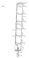
- Fig. 1 shows a basic structure of antenna in which a radome is removed.
- numeral 1 designates an antenna board in a shape of a rectangular plate a direction of a long side thereof is vertically supported.
- the antenna board 1 is made of, for example, PPE (PolyPhenylene Ether) (dielectric constant about 3.3), fluororesin of teflon (R) (dielectric constant about 2.3) or the like.
- the antenna board 1 has a feeding base be ing provided with a balance/unbalance convertingporti on 2, and connected to a feeder 3 formed by a coaxial cable and including a connector 4 at a front end thereof.
- the balance/unbalance converting portion 2 serves also as a matching circuit by, for example, balun.
- a pair of feeder lines 5, 5 that are parallel with each other are formed respectively on a front face and a back face of one end side of the antenna board 1 along the long side thereof via the balance/unbalance converting portion 2 at a base portion of the antenna board 1.
- pluralities of pairs of dipole antennas are formed by arranging antenna elements 6, 6, ... respectively bent in a semicircular shape and forming pairs along the feeder lines 5, 5 such that the antenna elements 6, 6, ... are supported by the feeder lines in a horizontal direction. That is, the pair of antenna elements 6, 6 respectively connected to the feeder lines 5, 5 function as a single dipole antenna, and a plurality of pairs thereof are aligned along the long side direction of the antenna board 1 and fed in series with electricity by the feeder lines 5, 5.
- antenna lengths in sum are set to be substantially ⁇ /2 ( ⁇ : wave length) of an object frequency and in this case, when the object frequency is set to 1900 [GHz], ⁇ /2 becomes about 78 [mm].
- a diameter of the dipole antenna in a ring-like shape is set to 0.18 ⁇ , that is, about 28 [mm).
- an array interval of the above-described respective dipole antennas are set to be variable by a necessary tilt angle relative to the horizontal direction. Specifically, when the array interval is set to 100 [mm] in correspondence with 1 ⁇ on the board, tilting is not carried out and radiation is carried out in a horizontal direction.
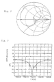
- Fig.2 through Fig. 4 and Fig, 8 show a measurement result when the respective array intervals of the dipole antennas are set to 100 [mm] to constitute the tilt angle in the horizontal direction to be 0° and dipole antennas by the antenna elements 6, 6, ... are constituted as 16 pairs.
- markers '1' through '3' shown by triangular marks in the drawings to cover a frequency band of PHS take following frequency values. That is,
- Fig.2 is a Smith chart indicating a result of measurement over a range of 200 [MHz] centering on the frequency 1902.05 [MHz] of the above-described marker '2'.
- the marker '1' is about 67 [ ⁇ ]
- the marker '2' is about 49 [ ⁇ ]
- the marker '3' is about 62 [ ⁇ ]
- the marker '2' of the center frequency takes a value approximated to an ideal value 50 [ ⁇ ] and therefore, it can be determined that substantially a desired characteristic can be realized.
- Fig.3 shows return loss
- return loss of the masker '1' of the above-described frequency is -16.277 [dB]
- return loss of the marker '2' is -27.812 [dB]
- return loss of the marker '3' is -16.646 [dB] and it is known that the return loss can be restrained to be equal to or smaller than -14 [dB] over a frequency range necessary for PHS.
- VSWR voltage standing wave ratio
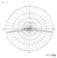
- Fig. 8 shows an example of measuring a radiation pattern in a vertical face. It can be understood that antenna radiation is carried out in the horizontal face by setting the tilt angle substantially to 0 degree as described above. Therefore, by forming the antenna structure with thus setting numerical characteristics or the like, when a base station is located at suburbs or the like where a population density is comparatively low and transmission and reception need to carry out over a wide range, the antenna emphasizing the characteristic in the horizontal face without setting the tilt angle of this kind is used.
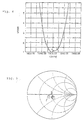
- Fig.5 through Fig, 7 and Fig. 9 show a measurement result when the respective array intervals of the dipole antennas are set to 93 [mm] to constitute the tilt angle of 8° (in lower direction of feeding side) and the dipole antennas by the antenna elements 6, 6, ... are constituted by 20 pairs.
- the markers '1' through '3' indicated by the triangular marks in the drawings to cover the frequency band of PHS take the following values of frequencies. That is,
- Fig. 5 is a Smith chart showing a result of measuring over a range of 200 [MHz] centering on the frequency 1902.05 [MHz] of the above-described marker '2'.
- the marker '1' is about 39 [ ⁇ ]
- the marker '2' is about 48 [ ⁇ ]
- the marker '3' is about 50 [ ⁇ ]
- the marker '2' of the center frequency and the marker '3' take values substantially approximated to an ideal value 50 [ ⁇ ] and therefore, it can be determined that substantially a desired characteristic can be realized.
- Fig.6 shows return loss
- return loss of the marker '1' having the above-described frequency is -17.700 [dB)
- return loss of the marker '2' is -33. 179 [dB]
- return loss of the marker '3' is -23.591 [dB] and it can be understood that the return loss can be restrained to be equal to or smaller than -14 [dB] over the frequency range necessary for PHS.
- VSWR of the marker '1' having the above-described frequency takes a value of 1. 2996
- VSDWR of the marker '2' takes a value of 1.0448
- VSWR of the marker '3' takes a value of 1.1415 and it is known that VSWR can be restrained to be equal to or smaller than 1.5 with sufficient allowance over the frequency range necessary for PHS.
- Fig.9 shows an example of measuring a radiation pattern of a vertical face and as described above, the tilt angle is substantially set to 8 degrees (in lower direction) . Therefore, by forming the antenna structure with thus setting numerical values or the like, when abase station is locatedon, for example, a roof of a building in an urban area or the like where the population density is comparatively high, and transmission and reception need to carry cut in a limited range, the antenna of this kind set to the tilt angle more less downward from the horizontal face is used.
- Fig.10 shows a radiation pattern in a horizontal face when the tilt angle is set to 0° which has been explained in the above-described first measurement example.
- Fig. 10 shows an excellent radiation characteristic uniformly substantially over an entire periphery of 360°, and it can be regarded that a desired non-directionality can be realized substantially perfectly.
- a total of the antenna can be accommodated inside of a radome in a shape of a circular pipe.
- a dimension in a direction of the short side of the antenna board 1 including the interval of the pair of the feeder line can be set to be small by feeding electricity to the antenna elements 6, 6, ... in series via the pair of parallel feeder lines 5, 5.
- the structure of the antenna per se is simple and excellent in productivity and the mechanical strength suitable for installation can be ensured but also the outer diameter of the total of the antenna including the antenna board 1 can be made to be small and slender.
- the antenna can be constituted to be very compact, easy in handling of installation or the like and excellent in weather resistance.
- the dimension in the short side direction of the antenna board 1 shown in Fig.1 is set to be substantially equal to the diameter of the dipole antennas in the ring-like shape and front ends of the respective antenna elements constituting the dipole antennas are respectively supported by an end portion of the antenna board 1 on a side opposed to a side of providing the feeder lines 5, 5 of the antenna board 1, the mechanical strength of the antenna elements 6, 6, ... can further be increased.
- the invention is not limited to the shape of the rectangular plate shape as in the antenna board 1 but, for example, an antenna supporting member in a shape of a round bar may be provided with the balance/unbalance converting portion 2 and the feeder lines 5, 5 and aligned with the antenna elements 6, 6, ...
- the invention is not limited to the frequency band used or use, a shape or an interval of aligning, or a number of aligning respective antenna elements or the like.
- the invention is not limited to the above-described embodiments but can be embodied by being variously modified within the range not deviated from a gist thereof.
- the above-described embodiments include various stages of inventions and various inventions can be extracted by pertinently combining a plurality of constituent essential conditions disclosed. For example, even when several constituent essential conditions are deleted from the total constituent essential conditions showing the embodiments, at least one of the problems described in the problems to be resolved by the invention can be resolved and when at least one of effects described in the effect of the invention is achieved, a constitution in which the constituent essential condition is deleted can be extracted as the invention.
Landscapes
- Variable-Direction Aerials And Aerial Arrays (AREA)
- Details Of Aerials (AREA)
Applications Claiming Priority (2)
| Application Number | Priority Date | Filing Date | Title |
|---|---|---|---|
| JP2003404827 | 2003-12-03 | ||
| JP2003404827A JP2005167705A (ja) | 2003-12-03 | 2003-12-03 | 水平偏波無指向性アレイアンテナ |
Publications (1)
| Publication Number | Publication Date |
|---|---|
| EP1538705A1 true EP1538705A1 (de) | 2005-06-08 |
Family
ID=34463982
Family Applications (1)
| Application Number | Title | Priority Date | Filing Date |
|---|---|---|---|
| EP04028752A Withdrawn EP1538705A1 (de) | 2003-12-03 | 2004-12-03 | Horizontal polarisiertes rundstrahlendes Antennenarray |
Country Status (5)
| Country | Link |
|---|---|
| US (1) | US20050128158A1 (de) |
| EP (1) | EP1538705A1 (de) |
| JP (1) | JP2005167705A (de) |
| KR (1) | KR100767209B1 (de) |
| CN (1) | CN100431220C (de) |
Cited By (2)
| Publication number | Priority date | Publication date | Assignee | Title |
|---|---|---|---|---|
| EP2058902A4 (de) * | 2007-04-12 | 2013-03-20 | Nec Corp | Antenne mit doppelter polarisationswelle |
| EP2589110A1 (de) * | 2010-07-01 | 2013-05-08 | Nokia Siemens Networks Oy | Antennenanordnung |
Families Citing this family (3)
| Publication number | Priority date | Publication date | Assignee | Title |
|---|---|---|---|---|
| JP4795898B2 (ja) * | 2006-08-30 | 2011-10-19 | マスプロ電工株式会社 | 水平偏波無指向性アンテナ |
| AU2013300234B2 (en) * | 2012-08-07 | 2015-07-23 | Comrod As | Three band whip antenna |
| CN106229613B (zh) * | 2016-08-23 | 2018-12-11 | 安谱络(苏州)通讯技术有限公司 | 一种正交双极化辐射天线及双极化全向阵列天线 |
Citations (3)
| Publication number | Priority date | Publication date | Assignee | Title |
|---|---|---|---|---|
| US3750185A (en) * | 1972-01-18 | 1973-07-31 | Westinghouse Electric Corp | Dipole antenna array |
| EP0340404A2 (de) * | 1988-05-06 | 1989-11-08 | Ball Corporation | L-förmige parasitäre Monopolelemente zum Übertragen von zirkular oder elliptisch polarisierten Wellen |
| US20020190912A1 (en) * | 2001-05-07 | 2002-12-19 | Lebaric Jovan E. | Planar high-frequency antenna |
Family Cites Families (10)
| Publication number | Priority date | Publication date | Assignee | Title |
|---|---|---|---|---|
| US2512137A (en) * | 1944-06-16 | 1950-06-20 | Us Sec War | Antenna |
| FR2061531B1 (de) * | 1969-04-15 | 1973-12-21 | Thomson Csf | |
| US4141014A (en) * | 1977-08-19 | 1979-02-20 | The United States Of America As Represented By The Secretary Of The Air Force | Multiband high frequency communication antenna with adjustable slot aperture |
| JP2574336B2 (ja) * | 1986-10-30 | 1997-01-22 | 三井石油化学工業株式会社 | 積層体 |
| JPH0537226A (ja) * | 1991-07-31 | 1993-02-12 | Mitsubishi Electric Corp | プリント・ダイポールアンテナ |
| JP2545663B2 (ja) * | 1991-12-06 | 1996-10-23 | 日本電信電話株式会社 | チルトビーム空中線 |
| SE506868C2 (sv) * | 1996-05-29 | 1998-02-23 | Allgon Ab | Långsträckt antenn samt metallförbindningselement |
| JP2002271135A (ja) * | 2001-03-07 | 2002-09-20 | Ueda Japan Radio Co Ltd | コリニアアンテナ |
| JP3735058B2 (ja) * | 2001-10-31 | 2006-01-11 | アンテナ技研株式会社 | 水平偏波無指向性アンテナ装置 |
| JP2003188636A (ja) * | 2001-12-17 | 2003-07-04 | Tdk Corp | 複合アンテナ |
-
2003
- 2003-12-03 JP JP2003404827A patent/JP2005167705A/ja active Pending
-
2004
- 2004-12-02 US US11/001,569 patent/US20050128158A1/en not_active Abandoned
- 2004-12-03 CN CNB2004100967393A patent/CN100431220C/zh not_active Expired - Fee Related
- 2004-12-03 KR KR1020040100799A patent/KR100767209B1/ko not_active Expired - Fee Related
- 2004-12-03 EP EP04028752A patent/EP1538705A1/de not_active Withdrawn
Patent Citations (3)
| Publication number | Priority date | Publication date | Assignee | Title |
|---|---|---|---|---|
| US3750185A (en) * | 1972-01-18 | 1973-07-31 | Westinghouse Electric Corp | Dipole antenna array |
| EP0340404A2 (de) * | 1988-05-06 | 1989-11-08 | Ball Corporation | L-förmige parasitäre Monopolelemente zum Übertragen von zirkular oder elliptisch polarisierten Wellen |
| US20020190912A1 (en) * | 2001-05-07 | 2002-12-19 | Lebaric Jovan E. | Planar high-frequency antenna |
Cited By (2)
| Publication number | Priority date | Publication date | Assignee | Title |
|---|---|---|---|---|
| EP2058902A4 (de) * | 2007-04-12 | 2013-03-20 | Nec Corp | Antenne mit doppelter polarisationswelle |
| EP2589110A1 (de) * | 2010-07-01 | 2013-05-08 | Nokia Siemens Networks Oy | Antennenanordnung |
Also Published As
| Publication number | Publication date |
|---|---|
| KR20050053514A (ko) | 2005-06-08 |
| US20050128158A1 (en) | 2005-06-16 |
| CN100431220C (zh) | 2008-11-05 |
| CN1624979A (zh) | 2005-06-08 |
| JP2005167705A (ja) | 2005-06-23 |
| KR100767209B1 (ko) | 2007-10-17 |
Similar Documents
| Publication | Publication Date | Title |
|---|---|---|
| US7471246B2 (en) | Antenna with one or more holes | |
| US6295028B1 (en) | Dual band antenna | |
| US6759990B2 (en) | Compact antenna with circular polarization | |
| CN101034765B (zh) | 互补宽带天线 | |
| CN1169387C (zh) | 折叠偶极天线 | |
| US8686912B2 (en) | 450 MHz folded dipole antenna | |
| US5757329A (en) | Slotted array antenna with single feedpoint | |
| SI20446A (sl) | Dualne mnogotrikotniške antene za GSM in DCS celično telefonijo | |
| US20050231437A1 (en) | Dipole antenna | |
| KR101859179B1 (ko) | 소형 광대역 대수 주기 안테나 | |
| EP1538705A1 (de) | Horizontal polarisiertes rundstrahlendes Antennenarray | |
| TW202215712A (zh) | 天線系統 | |
| KR100998153B1 (ko) | 안테나 시스템 | |
| CN103915685B (zh) | 一种基于印刷电路板的小尺寸宽带宽的四单元mimo天线 | |
| Roy et al. | New dual-frequency microstrip antennas for wireless communication | |
| Kosulvit et al. | A simple and cost-effective bidirectional antenna using a probe excited circular ring | |
| KR20110017977A (ko) | 다중절곡된 발룬부를 구비한 다이폴 안테나 | |
| CN112993551B (zh) | 应用于5G和6G频段的全向宽频WiFi天线 | |
| KR101816018B1 (ko) | 소형 광대역 대수 주기 안테나 | |
| Sun et al. | A wideband base station antenna with stable radiation pattern | |
| KR102062803B1 (ko) | 대수주기 다이폴 안테나 | |
| KR100393017B1 (ko) | 고주파 송수신용 마이크로 스트립 패치 어레이 안테나 | |
| KR100563118B1 (ko) | 유전체 기판을 이용한 다이폴 안테나 | |
| Ta et al. | A Low-Profile Base-Station Antenna | |
| Vahini et al. | A Wideband Dual Polarized Antenna for Mobile Base Stations |
Legal Events
| Date | Code | Title | Description |
|---|---|---|---|
| PUAI | Public reference made under article 153(3) epc to a published international application that has entered the european phase |
Free format text: ORIGINAL CODE: 0009012 |
|
| AK | Designated contracting states |
Kind code of ref document: A1 Designated state(s): AT BE BG CH CY CZ DE DK EE ES FI FR GB GR HU IE IS IT LI LT LU MC NL PL PT RO SE SI SK TR |
|
| AX | Request for extension of the european patent |
Extension state: AL BA HR LV MK YU |
|
| 17P | Request for examination filed |
Effective date: 20050624 |
|
| AKX | Designation fees paid |
Designated state(s): DE ES FR GB |
|
| 17Q | First examination report despatched |
Effective date: 20050727 |
|
| STAA | Information on the status of an ep patent application or granted ep patent |
Free format text: STATUS: THE APPLICATION IS DEEMED TO BE WITHDRAWN |
|
| 18D | Application deemed to be withdrawn |
Effective date: 20070314 |