EP1538617A2 - Skalierbare und expandierbare Einheiten für Datenspeichersystem - Google Patents
Skalierbare und expandierbare Einheiten für Datenspeichersystem Download PDFInfo
- Publication number
- EP1538617A2 EP1538617A2 EP04025817A EP04025817A EP1538617A2 EP 1538617 A2 EP1538617 A2 EP 1538617A2 EP 04025817 A EP04025817 A EP 04025817A EP 04025817 A EP04025817 A EP 04025817A EP 1538617 A2 EP1538617 A2 EP 1538617A2
- Authority
- EP
- European Patent Office
- Prior art keywords
- storage
- data
- cartridge
- magazine
- housing
- Prior art date
- Legal status (The legal status is an assumption and is not a legal conclusion. Google has not performed a legal analysis and makes no representation as to the accuracy of the status listed.)
- Withdrawn
Links
Images




Classifications
-
- G—PHYSICS
- G11—INFORMATION STORAGE
- G11B—INFORMATION STORAGE BASED ON RELATIVE MOVEMENT BETWEEN RECORD CARRIER AND TRANSDUCER
- G11B15/00—Driving, starting or stopping record carriers of filamentary or web form; Driving both such record carriers and heads; Guiding such record carriers or containers therefor; Control thereof; Control of operating function
- G11B15/675—Guiding containers, e.g. loading, ejecting cassettes
- G11B15/68—Automatic cassette changing arrangements; automatic tape changing arrangements
- G11B15/682—Automatic cassette changing arrangements; automatic tape changing arrangements with fixed magazines having fixed cassette storage cells, e.g. in racks
- G11B15/6835—Automatic cassette changing arrangements; automatic tape changing arrangements with fixed magazines having fixed cassette storage cells, e.g. in racks the cassettes being transferred to a fixed recorder or player using a moving carriage
-
- G—PHYSICS
- G11—INFORMATION STORAGE
- G11B—INFORMATION STORAGE BASED ON RELATIVE MOVEMENT BETWEEN RECORD CARRIER AND TRANSDUCER
- G11B15/00—Driving, starting or stopping record carriers of filamentary or web form; Driving both such record carriers and heads; Guiding such record carriers or containers therefor; Control thereof; Control of operating function
- G11B15/675—Guiding containers, e.g. loading, ejecting cassettes
- G11B15/68—Automatic cassette changing arrangements; automatic tape changing arrangements
-
- G—PHYSICS
- G11—INFORMATION STORAGE
- G11B—INFORMATION STORAGE BASED ON RELATIVE MOVEMENT BETWEEN RECORD CARRIER AND TRANSDUCER
- G11B15/00—Driving, starting or stopping record carriers of filamentary or web form; Driving both such record carriers and heads; Guiding such record carriers or containers therefor; Control thereof; Control of operating function
- G11B15/675—Guiding containers, e.g. loading, ejecting cassettes
- G11B15/68—Automatic cassette changing arrangements; automatic tape changing arrangements
- G11B15/682—Automatic cassette changing arrangements; automatic tape changing arrangements with fixed magazines having fixed cassette storage cells, e.g. in racks
- G11B15/683—Automatic cassette changing arrangements; automatic tape changing arrangements with fixed magazines having fixed cassette storage cells, e.g. in racks wherein the recorder or player is moved according to the location of a selected cassette
Definitions
- the present invention relates generally to a computer data archiving apparatus and, in particular to an automated data recording and playback apparatus utilizing tape cartridges.
- a common data archiving system includes one or more tape drives which utilize removable tape cartridges for recording and playback of the computer data.
- the tape cartridges have the benefit of large storage capacity and the ability to change cartridges to extend the storage capacity to a virtually infinite amount.
- manually operated tape drives require the presence of skilled personnel to exchange the tapes on a regular schedule.
- Autoloaders have been developed which automate the exchange of the tape cartridges into and out of the tape drives. These autoloaders move tapes generally one at a time from storage magazines, which hold a number and store of tape cartridges, to the tape drive and, upon completion of recording and/or playback from the tape drive, back to a storage location in the storage magazine. These autoloaders are generally connected into a computer system or computer network and are provided with an appropriate number of tape cartridges in the storage magazines. Autoloaders having a single drive record the data onto tapes one at a time in the drives. Autoloaders systems having multiple tape drives permit data to be provided simultaneously to the multiple drives nearly simultaneously, thereby reducing the data backup time.
- tape backup systems still suffer from the disadvantage that the transfer rate for the data to the tape cartridge or from the tape cartridge is limited compared to the transfer rate of data within most other components in the computer system or network.
- data backup and/or data archiving generally must be performed during downtimes for the computer system. For example, for a business that shuts down each day, the data backup is generally performed while the business is shut down.
- many businesses operate on a 24-hour schedule so that there is no ideal time for performing data backup. Even for those businesses which perform the data backup for the computer system during the hours when the business is shut down, failure of the computer system during working hours may result in the loss of some or all of a day's data since the failure may result in a complete loss of data since the last backup.
- the present invention provides a data storage system utilizing tape cartridges for recording data in a tape drive, which is supplied automatically with the cartridges via a cartridge shuttle.
- the cartridge shuttle moves the tape cartridges between the tape drive and storage locations in tape storage magazines.
- the present apparatus commonly referred to as an "auto loader” is housed within a housing, which is dimensioned to fit a standard form factor. Advantages are provided in the present invention by configuring the various operational components of the present "auto loader" to be replaceable by similar components having different dimensions so as to permit construction of an "auto loader” of a size to conform to a different form factor but without requiring re-design of the components.
- the present "auto loader” may be configured to scale to many different sizes while using common parts for each of the different sized units and only requiring changes in dimensions of a few key components.
- auto loader systems can be provided to fit different sized mounting locations or to accommodate different storage capacities without incurring high cost for re-design of differently proportioned components.
- the present data storage and retrieval device provides improvements on the data storage and retrieval device disclosed in United States Provisional Patent Application Serial No. 60/516,542, filed October 31, 2003, and the non-provisional application which claims the benefit thereof, as well as United States Provisional Patent Application, Serial Number 60/515,738 filed October 30, 2003, and the non-provisional application which claims the benefit thereof, all of which are incorporated herein by reference.
- an "auto loader" frame 10 has a substantially rectangular planer configuration with a bottom 12, side rails 14 and 16 and a transverse wall 18. Extending from the transverse wall 18 is a pair of longitudinal wall portions 20 and 22 between which is mounted a tape drive 24.
- the tape drive 24 is operable to read data from and write data to tape cartridge.
- a pair of magazine mounting rails 26 and 28 On the lower part 12 on the opposite side of the transverse wall 18 from the tape drive 24 are provided a pair of magazine mounting rails 26 and 28 on which storage magazines (as will be shown later) are mounted. Between the mounting rails 26 and 28 is a cartridge shuttle 30 that is movable along a transfer space 32 between the mounting rails 26 and 28.
- a motor 34 is provided adjacent the tape drive 24 and includes a transmission 36 which operate to move the cartridge shuttle 30 longitudinally along the transfer space 22.
- a printed circuit board 42 is provided adjacent the tape drive 24 and behind the transverse wall 18.
- the printed circuit board 42 includes circuit elements for control and operation of the present auto loader, as well as providing for data transmission between a computer or network to which the auto loader is connected and the tape drive 24.
- the present device is controlled through firmware on the printed circuit board 42 as well as through software running on the computer system or computer network to which the present device is connected.
- the frame 10 of the present auto loader is of a size and shape to fit into a standard computer rack.
- the "U" form factors such as 1U, 2U, 3U, and 4U, have defined dimensions of standard rack positions for computer equipment racks.
- the racks have a standard width in an X direction corresponding to a length along a direction X as shown in Figure 1 .
- the standard "U" form factors provide for a 19-inch X dimension.
- the Y dimension of the auto loader apparatus as indicated in Figure 1 by the arrow corresponds to the longitudinal dimension of the device. The Y dimension may be varied according to the needs of the user without requiring redesign of the components within the auto loader.
- the Z dimension as indicated in the drawing corresponds to the height of the auto loader.
- the height is denoted in the standard form factors as a "U" dimension and may be selected by the user from among the 1U, 2U, 3U, or 4U standard form factors.
- the dimensions of the components within the present auto loader may be varied along the Z direction to provide different "U" form factors without changing the design of the components.
- the present auto loader may be adapted to a users needs as to the space, which is consumed by the auto loader as to the storage capacity, which the auto loader capacity shall have.
- the variation in the Y and Z directions can be accomplished by using the same modular parts with only a few add on parts or specific parts for each "U" form factor.
- the mainframe or chassis 12 is identical for all "U" form factors within the same Y dimension.
- the frame need not be varied for different devices with the Z direction. Of course, for different Y dimensioned autoloaders, different frames 12 are provided.
- the cartridge shuttle 30 includes a shuttle base 42 on which is provided an elevator assembly 44 for lowering and raising a cartridge turntable or rotation housing 46 that in turn holds a cartridge retrieving and ejecting apparatus 48, such as a cartridge picker.
- the cartridge shuttle 30 has moved within the autoloader device by a belt 50 that is driven through a motor 52 and a reducer gear transmission 54 driving a drive pulley 56.
- the belt 50 is connected to second pulley 58 that is also mounted in the autoloader device.
- the shuttle base or chassis 42 is held to the belt 50 by belt clamps 60.
- the elevational movement of the cartridge held in the shuttle 30 is accomplished through rotation of threaded shafts 62, which are rotated through a belt driven by an elevator motor 64.
- the elevator motor and threaded shafts are held by an elevator support frame 66.
- the threaded shafts 62 carry threaded nuts attached to the rotator platform 46 to lift the rotator platform as needed.
- the rotator platform 46 includes a spur gear and spur gear ring (not shown) to cause rotation of the cartridge holding housing.
- the cartridge retrieving and injecting apparatus 48 moves within the cartridge holding housing to draw in or push out of their cartridges.
- the form factor of the present device may be varied in the Y direction by changing the length of the belt 50 to accommodate different formats of the autoloader apparatus. No other change in components is required for varying the Y dimension of the shuttle traverse assembly.
- the storage magazines 68 and 70 are mounted in the autoloader apparatus 10 on the rails 28 and 26.
- Each of the storage magazines 68 and 70 include a plurality of storage slots 72 into which is inserted data cartridges 74.
- the storage slots 72 are separated by divider walls 76.
- the storage magazines 68 and 70 also include front panels 78 and end caps 80.
- the storage magazines 68 and 70 are lengthened or shortened, as needed and may have more or fewer storage slots 72. This is accomplished by providing a greater or shorter length outer housing 84 which in the preferred embodiment is formed of sheet metal and by providing more or fewer separating walls 76. No other change is required in the parts or components for the storage magazines to accommodate a change in the Y dimension of the autoloader.
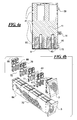
- Figures 4a through 4d are various views of the storage magazines 68 and 70 showing the interior of the storage slots 72 between the partition walls 76.
- the partition walls 76 extend primarily in the vertical direction between adjacent data cartridges and there is no requirement that a horizontal shelf be provided between the data cartridges.
- ejection springs 88 are disposed in each of the slots 72 to push the data cartridges 74 out of the slot when released by a latch.
- the latch is provided according to Figure 4A as a flexible portion 90 that engages the data cartridges 74 when they are positioned fully inserted into the slots 72.
- the scalability of the storage magazine is provided by including fewer or greater numbers of partition walls 76 along the length of a shorter or longer magazine housing 84 to expand the present apparatus in the lie direction.
- partition wall 76 having greater or fewer numbers of cartridge engaging spaces so that the storage magazines are either taller or shorter and have either greater or fewer numbers of cartridges stacked in each column.
- Figures 5a through 5d provide further details on the storage magazines including showing the latch 90 for the data cartridge in the partition wall 76.
- the latch 90 flexes on flexible members 92 that are cut free from the partition wall 76 by a slot 94 and a slot 96.
- a projection 98 that extends into an opening in the data cartridge 74. It is readily appreciated how the partition wall 76 can be expanded in height to accommodate a greater number of data cartridges by simply multiplying the structure required for each of the data cartridges so as to provide scalability of the present storage magazine.
- Figure 6 shows and enlarged detailed view of the cartridge shuttle 30 the chassis 42 can remain the same size for all sizes of the shuttle 30 as can the rotator assembly 46 and the cartridge housing 100.
- the cartridge retrieving and ejecting apparatus 48 can remain the same dimensions as well.
- the present invention provides that the elevator support frame 66 is replaced by shorter or taller frames as needed for a greater or lesser height in the Z direction for the present autoloader. This corresponds to different U sizes.
- the length of the threaded shafts 62 are changed to accommodate different vertical runs of the elevator mechanism 44.
- the other components in the cartridge shuttle can remain the same for different scaled sizes of the present device.
- the cartridge holder 100 has a data cartridge 74 mounted therein. Since the data cartridges are of a standard size, all of the scalability of the present autoloader for cartridges using a particular size is in parts other than the cartridge holder 100. In other words, no change needs to be made in this component so long as cartridges of a given size are used, no matter what change is made in the scale of the autoloader itself.
- the cartridge housing 100 is exchanged for a cartridge housing of an appropriate size to fit the cartridge format.
- the storage magazines would be sized according to the cartridge format.
- the chassis 42 of the present shuttle 30 includes the elevator mechanism 44 which is scaled by providing a different elevator support frame 66 and different lengths of shredded shafts 62, as discussed above.
- the threaded shafts carry threaded nuts 106 on which is supported the elevator platform 108 that moves vertically as the shafts 62 are rotated. Scaling of the present autoloader in either the Y or Z directions does not require changing of the elevator platform 108 or chassis 42.
- a housing 110 is shown in Figure 9 which includes rack mounting flanges 112 to mount in a standard computer network rack.
- the housing 110 fits over the chassis 112 as shown in Figure 1 to enclose the present autoloader.
- the housing 110 has changed in length in the Y direction.
- the housing 110 is increased in the Z direction to provide a greater or lesser height.
- the present invention provides a scalable autoloader which may be increased in size or deceased in size readily while retaining use of the majority of components and parts therein. Only a few parts and components have the present device must be exchanged in order to accomplish a change in the scale or size of the autoloader. This reduces the cost of parts and the cost of investment because many parts can be made identical for different sizes of the autoloader.
- the present invention is adapted easily to the needs of particular users depending upon how much space is to be consumed and what the storage capacity must be for the particular autoloader. Further, new versions of the present autoloader may be introduced with a minimal of retesting since the majority if components therein are already tested in autoloaders of different sizes.
- the present autoloader may be scaled by the provision of add on parts or specific parts for each size unit, such as providing these different packaged parts for scaling the autoloader to the end user or to an intermediate manufacturer.
- the present autoloader is illustrated with a two U version having two stacked cartridges in each space in the storage magazine.
- a one U version would be provided with storage magazines having only a single cartridge height storage magazine.
- the elevator mechanism may be foregone since there is no need to move the cartridges between levels of the storage magazine to another level of the storage magazine.
- the Main Chassis is identical for all "U”s within the same Y - dimension (identical concept).
- the Main Chassis will have a standard height independent of "U”s.
- the Top Cover will have different height dependent of "U”s.
- the Top Cover Y- Dimension must be changed accordingly. The concept remains the same .
Landscapes
- Automatic Tape Cassette Changers (AREA)
Applications Claiming Priority (2)
| Application Number | Priority Date | Filing Date | Title |
|---|---|---|---|
| US51560103P | 2003-10-30 | 2003-10-30 | |
| US515601P | 2003-10-30 |
Publications (2)
| Publication Number | Publication Date |
|---|---|
| EP1538617A2 true EP1538617A2 (de) | 2005-06-08 |
| EP1538617A3 EP1538617A3 (de) | 2007-11-21 |
Family
ID=34465389
Family Applications (1)
| Application Number | Title | Priority Date | Filing Date |
|---|---|---|---|
| EP04025817A Withdrawn EP1538617A3 (de) | 2003-10-30 | 2004-10-29 | Skalierbare und expandierbare Einheiten für Datenspeichersystem |
Country Status (2)
| Country | Link |
|---|---|
| US (1) | US7499242B2 (de) |
| EP (1) | EP1538617A3 (de) |
Families Citing this family (5)
| Publication number | Priority date | Publication date | Assignee | Title |
|---|---|---|---|---|
| US7532431B2 (en) * | 2006-03-15 | 2009-05-12 | Tandberg Storage Asa | Single elevator system and method for a tape automation system with a base unit and one or more add-on units |
| US7855938B2 (en) * | 2007-09-21 | 2010-12-21 | Tandberg Data Asa | Expandable data storage system and method with cartridge pass-through between cartridge handling units |
| US11388833B2 (en) * | 2020-02-06 | 2022-07-12 | Baidu Usa Llc | Modular-based solution for server rack architecture |
| US11657849B1 (en) * | 2022-06-13 | 2023-05-23 | Quantum Corporation | Reduced form factor, high-density, front-access only automated tape library |
| US12505323B2 (en) | 2024-03-29 | 2025-12-23 | Microsoft Technology Licensing, Llc | Optical data reader with multi-lane conveyor |
Family Cites Families (24)
| Publication number | Priority date | Publication date | Assignee | Title |
|---|---|---|---|---|
| US4812629A (en) * | 1985-03-06 | 1989-03-14 | Term-Tronics, Incorporated | Method and apparatus for vending |
| JPH07118128B2 (ja) * | 1986-04-14 | 1995-12-18 | ソニー株式会社 | カセツト移送装置 |
| US4910619A (en) * | 1987-09-16 | 1990-03-20 | Sony Corporation | Automatic changing system for cassette-type mediums |
| JPH052802A (ja) * | 1991-06-26 | 1993-01-08 | Sony Corp | カセツト移送機 |
| US5303214A (en) * | 1992-01-03 | 1994-04-12 | International Business Machines Corporation | Multi-media-type automatic libraries |
| DE4317546A1 (de) * | 1992-05-27 | 1994-01-20 | Funai Electric Co | Plattenspieler mit automatischem Plattenwechsler |
| JP2583017B2 (ja) * | 1993-04-14 | 1997-02-19 | インターナショナル・ビジネス・マシーンズ・コーポレイション | カートリッジ格納装置及び自動格納ライブラリ |
| JP2862765B2 (ja) * | 1993-07-28 | 1999-03-03 | 富士通株式会社 | 磁気テープ装置及び該装置における自動クリーニング方法 |
| US5586094A (en) * | 1994-07-28 | 1996-12-17 | P&P Marketing, Inc. | Apparatus and method for storing and playing optical disc with grooved opposing disc transfer arms |
| US5940356A (en) * | 1994-12-16 | 1999-08-17 | Toumbas; Christos | Modular compact disk filing system with automatic disk selection and playing, which permits modular expansion in all three dimensions |
| US6144519A (en) * | 1995-02-20 | 2000-11-07 | Fujitsu Limited | Library apparatus with a plurality of accessors |
| US6271982B1 (en) * | 1995-04-26 | 2001-08-07 | Qualstar Corporation | Automated precision cassette handling system |
| US5870245A (en) | 1995-11-09 | 1999-02-09 | Overland Data, Inc. | Modular cabinet for data storage media and drives |
| US5933396A (en) * | 1997-05-07 | 1999-08-03 | International Business Machines Corporation | Storage and retrieval library with side-by-side storage cells |
| US6262863B1 (en) * | 1998-07-01 | 2001-07-17 | Storage Technology Corporation | Automated storage library with rail mechanism providing flexible robot access |
| US6222699B1 (en) * | 1998-08-28 | 2001-04-24 | Hewlett-Packard Company | Modular data storage system utilizing a wireless cartridge access device |
| US6515822B1 (en) * | 1999-05-13 | 2003-02-04 | Hewlett-Packard Company | Modular data storage system with expandable vertical lift mechanism |
| US7451461B1 (en) | 1999-06-22 | 2008-11-11 | Hewlett-Packard Development Company, L.P. | Laterally expandable modular data storage system |
| US6473371B1 (en) * | 2000-02-14 | 2002-10-29 | Hewlett-Packard Company | Media handling device having replaceable modules |
| US6829116B1 (en) * | 2000-11-10 | 2004-12-07 | Quantum Corporation | Automated tape cartridge autoloader/library system |
| US6693759B2 (en) * | 2000-11-10 | 2004-02-17 | Quantum Corporation | Compact form factor for an automated tape cartridge autoloader/library system |
| US6983469B2 (en) * | 2001-02-21 | 2006-01-03 | Bdt Buro-Und Datentechnik Gmbh & Co Kg | Modular system with multi-drives and multi-magazines for storing data |
| US6735042B2 (en) * | 2001-11-07 | 2004-05-11 | Tandberg Data Asa | Tape cartridge lifting device |
| US6816335B2 (en) | 2001-11-09 | 2004-11-09 | Tandberg Data Asa | Cartridge transport and loading apparatus and method |
-
2004
- 2004-10-29 US US10/976,472 patent/US7499242B2/en not_active Expired - Fee Related
- 2004-10-29 EP EP04025817A patent/EP1538617A3/de not_active Withdrawn
Also Published As
| Publication number | Publication date |
|---|---|
| US7499242B2 (en) | 2009-03-03 |
| EP1538617A3 (de) | 2007-11-21 |
| US20050146808A1 (en) | 2005-07-07 |
Similar Documents
| Publication | Publication Date | Title |
|---|---|---|
| JP4105121B2 (ja) | 電子機器の筐体構造、及びディスクアレイ装置 | |
| US6515822B1 (en) | Modular data storage system with expandable vertical lift mechanism | |
| US6309162B1 (en) | Data storage system with redundant media handling assemblies | |
| US8868866B2 (en) | Configurable tape loader with internal hard-disk | |
| JP4166406B2 (ja) | データ・カートリッジ交換装置、およびデータ・カートリッジに使用者がアクセスすることを可能とする方法 | |
| JP2003109270A (ja) | データ記憶システム用の、着脱式媒体の格納装置および媒体格納方法 | |
| US7855938B2 (en) | Expandable data storage system and method with cartridge pass-through between cartridge handling units | |
| JP2003109267A (ja) | データ記憶システム内に着脱式の媒体ハンドリングシステムを設けるシステムおよび方法 | |
| JP2003132606A (ja) | 媒体格納装置内にてデータ媒体を保持する装置および方法 | |
| EP0868722A1 (de) | X-y-positioniersystem für bibliothekskassetten-handhabung | |
| EP0982723A2 (de) | Modulares Datenspeicherungssystem | |
| US7499242B2 (en) | Scalable and expandable units for data storage system | |
| US6498771B1 (en) | Data storage unit having plural removable magazines | |
| US6956715B2 (en) | High-density media storage system | |
| DE60116580T2 (de) | Automatisches Bibliotheksystem mit automatischer Ladung von Bandkassetten | |
| JP2003132607A (ja) | データ記憶システム用の一括アクセスシステム | |
| US7184242B1 (en) | Self-contained robotics module for storage library | |
| JP2003162856A (ja) | データ記憶システム内のデータ媒体用格納トレー | |
| JP2001052415A (ja) | 横方向に拡張可能なモジュラ式データ記憶システム | |
| CN1815594B (zh) | 用于数据存储系统的可升级和可扩展装置 | |
| EP1176597B1 (de) | Rekonfigurierbares Kassettenverarbeitungsmodul zur Speicherung von Kassettenaufnahmevorrichtungen in ein Datenspeichersystem | |
| US7227716B2 (en) | Two tape, four reel cartridge and drive for wide magnetic recording tape | |
| CN1811963B (zh) | 数据盒箱及其操作方法 | |
| JP2847327B2 (ja) | テープカートリッジシステムにおけるローダ機構 | |
| JP2003122511A (ja) | データ記憶システム内のデータ媒体へのアクセスを実現するシステムおよび方法 |
Legal Events
| Date | Code | Title | Description |
|---|---|---|---|
| PUAI | Public reference made under article 153(3) epc to a published international application that has entered the european phase |
Free format text: ORIGINAL CODE: 0009012 |
|
| AK | Designated contracting states |
Kind code of ref document: A2 Designated state(s): AT BE BG CH CY CZ DE DK EE ES FI FR GB GR HU IE IT LI LU MC NL PL PT RO SE SI SK TR |
|
| AX | Request for extension of the european patent |
Extension state: AL HR LT LV MK |
|
| PUAL | Search report despatched |
Free format text: ORIGINAL CODE: 0009013 |
|
| AK | Designated contracting states |
Kind code of ref document: A3 Designated state(s): AT BE BG CH CY CZ DE DK EE ES FI FR GB GR HU IE IT LI LU MC NL PL PT RO SE SI SK TR |
|
| AX | Request for extension of the european patent |
Extension state: AL HR LT LV MK |
|
| 17P | Request for examination filed |
Effective date: 20080403 |
|
| 17Q | First examination report despatched |
Effective date: 20080520 |
|
| AKX | Designation fees paid |
Designated state(s): DE GB |
|
| STAA | Information on the status of an ep patent application or granted ep patent |
Free format text: STATUS: THE APPLICATION IS DEEMED TO BE WITHDRAWN |
|
| 18D | Application deemed to be withdrawn |
Effective date: 20090501 |