EP1538564B1 - Bildverarbeitungssystem und Bildverarbeitungsverfahren - Google Patents
Bildverarbeitungssystem und Bildverarbeitungsverfahren Download PDFInfo
- Publication number
- EP1538564B1 EP1538564B1 EP04257455A EP04257455A EP1538564B1 EP 1538564 B1 EP1538564 B1 EP 1538564B1 EP 04257455 A EP04257455 A EP 04257455A EP 04257455 A EP04257455 A EP 04257455A EP 1538564 B1 EP1538564 B1 EP 1538564B1
- Authority
- EP
- European Patent Office
- Prior art keywords
- image information
- vectorization
- image
- reading
- procedure
- Prior art date
- Legal status (The legal status is an assumption and is not a legal conclusion. Google has not performed a legal analysis and makes no representation as to the accuracy of the status listed.)
- Expired - Lifetime
Links
Images


Classifications
-
- H—ELECTRICITY
- H04—ELECTRIC COMMUNICATION TECHNIQUE
- H04N—PICTORIAL COMMUNICATION, e.g. TELEVISION
- H04N1/00—Scanning, transmission or reproduction of documents or the like, e.g. facsimile transmission; Details thereof
- H04N1/41—Bandwidth or redundancy reduction
-
- G—PHYSICS
- G06—COMPUTING OR CALCULATING; COUNTING
- G06Q—INFORMATION AND COMMUNICATION TECHNOLOGY [ICT] SPECIALLY ADAPTED FOR ADMINISTRATIVE, COMMERCIAL, FINANCIAL, MANAGERIAL OR SUPERVISORY PURPOSES; SYSTEMS OR METHODS SPECIALLY ADAPTED FOR ADMINISTRATIVE, COMMERCIAL, FINANCIAL, MANAGERIAL OR SUPERVISORY PURPOSES, NOT OTHERWISE PROVIDED FOR
- G06Q40/00—Finance; Insurance; Tax strategies; Processing of corporate or income taxes
- G06Q40/04—Trading; Exchange, e.g. stocks, commodities, derivatives or currency exchange
-
- G—PHYSICS
- G06—COMPUTING OR CALCULATING; COUNTING
- G06Q—INFORMATION AND COMMUNICATION TECHNOLOGY [ICT] SPECIALLY ADAPTED FOR ADMINISTRATIVE, COMMERCIAL, FINANCIAL, MANAGERIAL OR SUPERVISORY PURPOSES; SYSTEMS OR METHODS SPECIALLY ADAPTED FOR ADMINISTRATIVE, COMMERCIAL, FINANCIAL, MANAGERIAL OR SUPERVISORY PURPOSES, NOT OTHERWISE PROVIDED FOR
- G06Q50/00—Information and communication technology [ICT] specially adapted for implementation of business processes of specific business sectors, e.g. utilities or tourism
- G06Q50/10—Services
- G06Q50/18—Legal services
- G06Q50/188—Electronic negotiation
-
- H—ELECTRICITY
- H04—ELECTRIC COMMUNICATION TECHNIQUE
- H04N—PICTORIAL COMMUNICATION, e.g. TELEVISION
- H04N2201/00—Indexing scheme relating to scanning, transmission or reproduction of documents or the like, and to details thereof
- H04N2201/32—Circuits or arrangements for control or supervision between transmitter and receiver or between image input and image output device, e.g. between a still-image camera and its memory or between a still-image camera and a printer device
- H04N2201/3201—Display, printing, storage or transmission of additional information, e.g. ID code, date and time or title
- H04N2201/3225—Display, printing, storage or transmission of additional information, e.g. ID code, date and time or title of data relating to an image, a page or a document
- H04N2201/3242—Display, printing, storage or transmission of additional information, e.g. ID code, date and time or title of data relating to an image, a page or a document of processing required or performed, e.g. for reproduction or before recording
Definitions
- the present invention relates to an image processing system and image processing method, which convert image information scanned by an image processing apparatus such as a copying machine or the like into vector data that can be re-used by a document creation application software.
- MFPs digital multifunction peripherals
- an MFP which recognizes character information included in image data obtained by scanning a document and associates it with font data (e.g., Japanese Patent Laid-Open No. 5-12402 ). This arrangement facilitates re-use and re-editing of a paper document and the like.
- the present invention has been proposed to solve the conventional problems, and has as its objects to provide an image processing system and image processing method which can appropriately set whether to convert an original paper document into re-usable vector data before obtaining vector data from the paper document.
- an image processing system as claimed in claim 1.
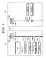
- Fig. 1 is a block diagram showing the arrangement of an image processing system according to the first embodiment of the present invention.
- the image processing system in Fig. 1 is implemented in an environment in which offices 10 and 20 are connected via a network 104 such as the Internet.
- an MFP 100, a management PC 101 for controlling the MFP 100, a client PC 102, a document management server 106a, its database 105a, and a proxy server 103a are connected to a LAN 108 formed in the office 20, a document management server 106b, its database 105b, and a proxy server 103b are connected.
- the client PC 102 comprises an external storage unit, search image input unit, and search result output unit.
- the LAN 107 and the LAN 108 in the office 20 are connected to the network 104 such as the Internet via the proxy servers 103a and 103b.
- the MFP 100 has charge of an image scanning process of optically scanning a paper document and converting it into an image signal and some of image processes for the scanned image signal in this embodiment, and supplies an image signal to the management PC 101_via a LAN 109.
- the management PC 101 can be implemented by a general PC, which incorporates an image storage unit, image processing unit, display, input unit, and the like. Some or all of the components of the management PC 101 may be integrally formed with the MFP 100.
- FIG. 2 is a block diagram showing the arrangement of the MFP 100 according to the first embodiment of the present invention.
- an image scanning unit 110 including an auto document feeder (to be abbreviated as an "ADF" hereinafter) irradiates a document image on one or a plurality of stacked documents with light coming from an internal light source, forms an image of light reflected by the document on a solid-state image sensing element via a lens, and obtains a scanned image signal in the raster order as image information at a resolution of, e.g., 600 dpi, from the solid-state image sensing element.
- ADF auto document feeder
- a data processing device 115 executes an image process of that image signal to convert it into a recording signal.
- the data processing device 115 temporarily stores recording data of one page in a storage device 111, and sequentially outputs that data to a printing device 112, thus printing images on paper sheets.
- Print data output from the client PC 102 is input to the MFP 100 via the LAN 107, is received by the data processing device 115 via a network I/F 114, and is then converted into recordable raster data by the data processing device 115. The raster data is then output to the printing device 112 to print a recording image on a paper sheet.
- the operator inputs instructions to the MFP using an input device 113 such as a key equipped on the MFP, or an input device of the management PC 101 which includes a keyboard and mouse. Such series of operations are controlled by a controller in the data processing device 115.
- a display device 116 of the MFP 100, the monitor of the management PC 101, or the monitor of the client PC 102 displays status of operation inputs and image data whose process is underway.
- the storage device 111 is also controlled from the management PC 101, and data exchange and control between the MFP 100 and the management PC 101 are done via a network I/F 117 and the directly connected LAN 109.
- Fig. 3 is a flowchart for explaining the procedure for an image process by the image processing system according to the first embodiment of the present invention. A process of scanning a paper document to obtain image information will be described with reference to the flowchart in Fig. 3 .
- the image scanning unit 110 of the MFP 100 is enabled to raster-scan one original and to obtain, e.g., a 8-bit image signal of a 600 dpi (image information input process: step S1200).
- This image signal undergoes a pre-process by the data processing device 115, and is stored as image data of one page in the storage device 111.
- a CPU of the management PC 101 separates regions of a text/line image part and halftone image part from the image signal stored in the storage device 111.
- the CPU further separates a text part into blocks combined as clusters for respective paragraphs and a line image part into tables and graphics formed of lines, and converts these blocks, tables, and graphics into segments.
- the CPU segments the image part expressed by halftone into independent objects for respective so-called blocks (e.g., a rectangular image part block, background part block, and the like) (block selection (BS) process: step S1201).
- blocks e.g., a rectangular image part block, background part block, and the like
- a two-dimensional barcode or an object corresponding to URL which is recorded in the document image as additional information, is detected.
- the URL undergoes character recognition in an OCR (optical-character recognition) process, and the two-dimensional barcode or object is decoded (step S1202).
- Vectorization control information of the document is detected from the decoding result (step S1203).
- the vectorization control information represents inhibition or permission of vectorization for each of objects of a document, each of object types, or a specific object.
- a method of using a digital watermark to embed information imperceptible to the human eye such as a method of embedding information between neighboring characters by modulating the spacings between them at a plurality of positions, a method of embedding information of a specific frequency in a halftone image, or the like may be adopted. If the additional information is embedded as a digital watermark, the watermark information is detected and is decoded in step S1202. As described above, the vectorization control information may have any format as far as it can attain the objects of this embodiment.
- step S1204 If it is determined in step S1204 that the input image information has no vectorization control information (NO), the image information is directly stored in the storage device 111 (step S1208). On the other hand, if any vectorization control information is found in step S1204 (YES), the flow branches to step S1205.
- step S1205 It is determined in step S1205 on the basis of the vectorization control information whether vectorization is permitted. If it is determined that vectorization is permitted (YES), the image information is vectorized (step S1206).
- the process in step S1206 comprises conversion of image information into vector data and converts the image information into an electronic file close to the original electronic file.
- the size, style, and font of characters are further recognized to convert the text blocks into font data which are visually faithful to characters obtained by scanning the document.
- table and graphic blocks formed of lines are converted into outline data.
- Image blocks are processed as an independent JPEG file as image data. Such vectorization processes are executed for respective objects, and layout information of the objects is saved. These objects and layout information are converted into application data such as an rtf file (step S1207), and the application data is stored in the storage device 111 as an electronic file (step S1208).
- step S1205 If it is determined in step S1205 that vectorization is inhibited (NO), the flow branches to step S1208 to directly store the image information as an electronic file in the storage device 111.
- This direct storage of the image information in the storage device 111 prevents text data in the image information from being tampered by application software or prevents the image information from being manipulated as graphic data.
- the original information can directly be stored. That is, data obtained by scanning a paper document and formed in a format which cannot be re-used can directly be stored.
- index information for such search process is generated and is added to a search index file (step S1209).
- the operator is notified of the storage address of the electronic file (step S1210), and pointer information indicating the storage address is appended to the file as image information (step S1211).
- a document recording, editing, transfer, and storage processes can be executed using an electronic file itself obtained by the procedure for the above-mentioned processes to step S1211 (step S1212).
- the processes from step S1213 indicate the procedure for an image output process of reading out and outputting an electronic file obtained by the processes to step S1212 as vectorized data or image data from the storage device 111.
- a CPU (not shown) reads out an image which is stored in the storage device 111 of the MFP 100 as an electronic file from a stored image signal and converts the image into recordable raster data in the data processing device 115. It is determined in step S1213 whether any vectorization control information is detected. If any vectorization control information is detected (YES), the vectorization control information is appended (step S1216).
- step S1214 a condition set by the operator as to whether to execute vectorization control is further determined. If vectorization control is necessary (YES), vectorization control information is generated (step S1215), and the generated vectorization control information is appended (step S1216). In step S1217, the image, which has been converted into vector data, is printed and output from the printing device 112 on a medium such as a paper sheet or the like.
- Vectorization control information detected in this embodiment makes it possible to control input image information on the basis of the permission/inhibition of re-use and implement an image processing system having more improved maintainability of input image information than a conventional one.
- vectorization is executed when it is determined in step S1204 that an input has no vectorization control information.
- control may be executed so as to skip vectorization. Either arrangement to select depends on to which to give priority, the convenience of vectorization or the security or copyright of an original document.
- the image processing system may be arranged such that the operator can arbitrarily select either one.
- the block selection (BS) process indicated by step S1201 will be described first.
- Fig. 4 is a view showing how a block selection process determines the property of one scanned image data and divides the image data into a plurality of blocks. More specifically, in the block selection process, image data of one page scanned in step S1200 indicated by reference numeral 41 is recognized as clusters for respective objects (as indicated by reference numeral 42), properties such as text (TEXT), photo (PHOTO), line (LINE), table (TABLE), and the like of respective blocks are determined, and the image data is segmented into regions (blocks) having different properties.
- An input image is binarized to a monochrome image, and a cluster of pixels bounded by an outline of black pixels is extracted by outline tracing of black pixels.
- outline tracing is also made for white pixels in the cluster to extract clusters of white pixels.
- a cluster of black pixels is recursively extracted from the cluster of white pixels with a predetermined area or more.
- the obtained clusters of black pixels are classified into regions having different properties in accordance with their sizes and shapes. For example, a pixel cluster which has an aspect ratio close to 1, and has a size that falls within a predetermined range is determined as that corresponding to a character. Furthermore, a part where neighboring characters regularly line up and can be grouped is determined as a text region.
- a flat pixel cluster is categorized as a line region
- a range occupied by black pixel clusters that include rectangular white pixel clusters which have a predetermined size or more and regularly line up is categorized as a table region
- a region where pixel clusters with indeterminate forms are distributed is categorized as a photo region
- any other pixel cluster with an arbitrary shape is categorized as a picture region, and so forth.
- Fig. 5 is a view showing an example of the block information for the blocks obtained in the block selection process. These pieces of information for respective blocks shown in Fig. 5 are used to execute vectorization, as will be described later.
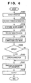
- step S1202 The OCR/OMR process (indicated by step S1202) of extracting vectorization control information from scanned image data will be described first.
- Fig. 6 is a flowchart for explaining the procedure for decoding a two-dimensional barcode (QR code symbol) appended into a document image and outputting a data character string.
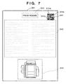
- Fig. 7 is a view showing an example of a document 310 appended with a two-dimensional barcode.
- the internal CPU scans image data which is stored in a page memory in the data processing device 115 and is obtained by scanning the document 310 to detect the position of a predetermined two-dimensional barcode symbol 311 from the result of the above-mentioned block selection process.
- a position detection pattern of a QR code is made up of identical position detection element patterns 311a to 311c, which are located at three out of the four corners of the symbol (step S300).
- step S301 format information that neighbors the position detection pattern is decoded to obtain an error correction level and mask pattern applied to the symbol.
- an encoded region bit pattern is XORed using the mask pattern obtained from the format information to cancel the mask process (step S303).
- a symbol character is read in accordance with the layout rule corresponding to the model so as to decode message data and an error correction code word (step S304). It is detected if a decoded code includes an error (step S305). As a result, if any error is detected (YES), that error is corrected (step S306). A data code word is divided into segments on the basis of a mode indicator and character count indicator from the error-corrected data (step S307). Finally, data characters are decoded on the basis of a specification mode, thus outputting the result (step S308). If no error is detected in step S305 (NO), the flow advances to step S307.
- Data to be encoded in the two-dimensional barcode represents vectorization control information.
- vectorization control information may be recorded using a character string.
- a block of a character string according to a predetermined rule is detected by the above block selection process, and characters of the character string that indicates the pointer information undergo character recognition, thus directly obtaining the vectorization control information.
- vectorization control information can be assigned by embedding watermark information in the character spacings by applying imperceptible modulation to, e.g., the spacings between neighboring characters in a character string of a text block 312 or 313 of the document 310 shown in Fig. 7 .
- vectorization control information can be acquired by detecting the character spacings upon executing a character recognition process (to be described later).
- vectorization control information can be assigned as a digital watermark in a natural image block 314.
- step S1206 in Fig. 3 The vectorization process indicated by step S1206 in Fig. 3 will be described below.
- a character recognition process is executed for each character of text blocks.
- a character recognition process an image extracted for each character is recognized using one of pattern matching methods to obtain a corresponding character code.
- an observation feature vector obtained by converting a feature acquired from a character image into a several-ten-dimensional numerical value string is compared with a dictionary feature vector obtained in advance for each character type, and a character type with a shortest distance is output as a recognition result.
- Various known methods are available for feature vector extraction. For example, a method of dividing a character into a mesh pattern, and counting character lines in respective meshes as line elements depending on their directions to obtain a (mesh count)-dimensional vector as a feature can be adopted.
- step S1201 When a text-region extracted by the block selection process (step S1201) undergoes character recognition, the writing direction (horizontal or vertical) is determined for that region, lines are extracted in the corresponding directions, and character images are then obtained by extracting characters.
- the writing direction horizontal or vertical
- horizontal and vertical projections of pixel values in that region are calculated, and if the variance of the horizontal projection is larger than that of the vertical projection, that region can be determined as a horizontal writing region; otherwise, that region can be determined as a vertical writing region.
- a plurality of sets of dictionary feature vectors for the number of character types used in character recognition are prepared in correspondence with character shape types, i.e., font types, and a font type is output together with a character code upon matching, thus recognizing the font of a character.
- information of a character part is converted into vector data, using a character code and font information obtained by the character recognition process, and outline data prepared in advance. If an original document is a color document, the color of each character is extracted from the color image and is recorded together with vector data.
- image information which belongs to a text block can be converted into vector data with a nearly faithful shape, size, and color. This makes it possible to handle high-quality text data.
- outlines of pixel clusters extracted in each region of interest are converted into vector data. More specifically, a point sequence of pixels which form an outline is divided into sections at a point which is considered as a corner, and each section is approximated by a partial line or curve. Note that "corner” means a point corresponding to a maximal curvature.
- Fig. 8 is a view for explaining a point corresponding to a maximal curvature.
- the point corresponding to the maximal curvature is obtained as a point where the distance between an arbitrary point Pi and a chord which is drawn between points Pi-k and Pi+k separated k points from the point Pi in the left and right directions becomes maximal.
- R be the chord length/arc length between Pi-k and Pi+k.
- Sections obtained after division at each corner can be vectorized using a method of least squares or the like with respect to a point sequence for a line, and a ternary spline function or the like for a curve.
- an outline of a graphic with an arbitrary shape can be converted into vector data.
- the color of a graphic is extracted from the color image and is recorded together with vector data.
- Fig. 9 is a view for explaining an example wherein an outside outline which is close to an inside outline or another outside outline is expressed as a line with a given width.
- an outside outline is close to an inside outline or another outside outline in a given section, as shown in Fig. 9 , two outlines may be combined to express a line with a given width. More specifically, lines are drawn from respective points Pi on a given outline to points Qi on another outline, each of which has a shortest distance from the corresponding point.
- the distances PQi maintain a constant value or less on the average, the section of interest is approximated by a line or curve using PQi middle points as a point sequence, and the average value of the distances PQi is set as the width of that line or curve.
- a line or a table ruled line as a set of lines can be efficiently expressed as vector data as a set of lines having a given width, as described above.
- a character which has the shortest distance from a dictionary as a result of the character recognition process is used as a recognition result, as described above.
- this distance is equal to or larger than a predetermined value
- the recognition result does not always match an original character, and a wrong character having a similar shape is often recognized. Therefore, in the present invention, such character is handled in the same manner as a general line art, as described above, and is converted into outline data. That is, even a character that causes a recognition error in the conventional character recognition process can be prevented from being vectorized to a wrong character, but can be vectorized based on outline data which is visually faithful to image data.
- a block determined as a photo block is not vectorized in the present invention, and is output as image data without any modification.
- Fig. 10 is a flowchart for explaining the procedure for a process executed until vector data are grouped for each graphic object.
- Initial and terminal points of each vector data are calculated (step S700).
- a graphic element is detected (step S701). Detecting a graphic element is to detect a closed graphic formed by partial lines. Such detection is made by applying the principle that each vector which forms a closed shape has vectors coupled to its two ends.
- step S702 other graphic elements or partial lines present in the graphic element are grouped to set a single graphic object (step S702). If other graphic elements or partial lines are not present in the graphic element, that graphic element is set as a graphic object.
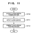
- Fig. 11 is a flowchart for explaining the procedure for a process of detecting a graphic element.
- Closed graphic forming vectors are extracted from vector data by excluding unwanted vectors, two ends of which are not coupled to other vectors (step S710).
- An initial point of a vector of interest of the closed graphic forming vectors is set as a start point, and vectors are traced clockwise in turn. This process is made until the start point is reached, and all passing vectors are grouped as a closed graphic that forms one graphic element (step S711). Also, all closed graphic forming vectors present in the closed graphic are grouped in this case.
- an initial point of a vector which is not grouped yet is set as a start point, and the above process is repeated.
- those which join the vectors grouped as the closed graphic in step S711 are detected and are grouped as one graphic element (step S712).
- a graphic block can be handled as an independently re-usable graphic object.
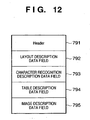
- Fig. 12 is a view showing the data structure of a file in an intermediate data format obtained as the conversion result of the block selection process (step S1201) and vectorization process (step S1206) for image data of one page.
- the data format shown in Fig. 12 is called a document analysis output format (DAOF) hereinafter. That is, Fig. 12 shows the DAOF data structure.
- DAOF document analysis output format
- reference numeral 791 denotes a Header which holds information associated with document image data to be processed.
- Reference numeral 792 denotes a layout description data field which holds property information and block address information of respective blocks which are recognized for respective properties such as TEXT (text), TITLE (title), CAPTION (caption), LINEART (line art), PICTURE (natural image), FRAME (frame), TABLE (table), and the like.
- Reference numeral 793 denotes a character recognition description data field which holds character recognition results obtained by executing character recognition of TEXT blocks such as TEXT, TITLE, CAPTION, and the like.
- Reference numeral 794 denotes a table description data field which stores details of the structure of TABLE blocks.
- Reference numeral 795 denotes an image description data field which stores image data of PICTURE blocks, LINEART blocks, and the like extracted from the document image data.
- DAOF data itself is often saved as a file in place of intermediate data.
- a general document creation application cannot re-use individual objects.
- a process of converting the DAOF data into application data (step S1210) will be described in detail below.
- Fig. 13 is a flowchart for explaining the schematic procedure for the entire application data conversion process.
- DAOF data is input (step S800).
- a document structure tree which serves as a basis of application data is generated (step S802).
- Actual data in the DAOF are input based on the document structure tree, thus generating actual application data (step S804).
- Fig. 14 is a flowchart for explaining the detailed procedure of a document structure tree generation process (step S802).
- Figs. 15A and 15B are views for explaining an overview of a document structure tree.
- the flow of processes transits from a microblock (single block) to a macroblock (a set of blocks).
- a block indicates a microblock and macroblock.
- Re-grouping is done for respective blocks on the basis of relevance in the vertical direction (step S802a). Immediately after the flow starts, determination is made for respective microblocks. Note that relevance can be defined by checking if the distance between neighboring blocks is small, blocks have nearly the same block widths (heights in the case of the horizontal direction), and so forth. Information of the distances, widths, heights, and the like can be extracted with reference to the DAOF.
- Fig. 15A shows an actual page configuration
- Fig. 15B shows a document structure tree of that page.
- T3, T4, and T5 form one group V1
- T6 and T7 form one group V2
- these groups are generated as those which belong to an identical layer.
- a separator is an object which has a line property in the DAOF.
- a separator is an element which explicitly divides blocks in an application. Upon detection of a separator, a group is re-divided in the identical layer.
- step S802c It is then determined using a group length whether no more divisions are present (step S802c). For example, it is determined whether the grouping length in the vertical direction agrees with a page height. If the group length in the vertical direction agrees with the page height (YES), the document structure tree generation process ends. For example, in the case of the structure shown in Figs. 15A and 15B , groups V1 and V2 have no separator, and their group height does not agree with the page height. Hence, NO is determined in step S802c, and the flow advances to step S802d.
- step S802d re-grouping is done for respective blocks on the basis of relevance in the horizontal direction. Note that the first determination immediately after the flow starts is made for respective microblocks in this re-grouping. Definitions of relevance and its determination information are the same as those in the vertical direction. For example, in the case of the structure shown in Figs. 15A and 15B , T1 and T2 generate group H1, and V1 and V2 generate group H2. Groups H1 and H2 are generated as those which belong to an identical layer one level higher than V1 and V2.
- step S802e The presence/absence of a separator in the horizontal direction is checked (step S802e). Since Figs. 15A and 15B include separator S1, that separator is registered in a tree, thus generating layers H1, S1, and H2. It is determined using a group length whether no more divisions are present (step S802f). For example, it is determined whether the grouping length in the horizontal direction agrees with a page width. As a result, if the group length in the horizontal direction agrees with the page width (YES), the document structure tree generation process ends. On the other hand, if the group length in the horizontal direction does not agree with the page width (NO), the flow returns to step S802b to repeat the processes from relevance check in the vertical direction in an upper layer by one level. For example, in the case of the structure shown in Figs. 15A and 15B , since the group length agrees with the page width, the process ends, and uppermost layer V0 that represents the entire page is finally appended to the document structure tree.
- step S804. application data is generated based on that information in step S804.
- a practical example in the case of the structure shown in Figs. 15A and 15B will be explained below.
- H1 since H1 includes two blocks T1 and T2 in the horizontal direction, it is output as two columns. After internal information of T1 (with reference to the DAOF, text as the character recognition result, image, and the like) is output, a new column is set, and internal information of T2 is output. After that, separator S1 is output. Since H2 includes two blocks V1 and V2 in the horizontal direction, it is output as two columns. Internal information of V1 is output in the order of T3, T4, and T5, and a new column is set. Then, internal information of V2 is output in the order of T6 and T7. In this manner, the conversion process into application data can be done. This makes it possible to re-use a vectorized object in existing document creation application software or the like.
- a vectorization control information generation/appending process in steps S1215 and S1216 will be described in detail below.
- the vectorization control information generation/appending process is executed immediately before printing an image on a recording medium such as a paper sheet or the like.
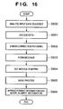
- Fig. 16 is a flowchart for explaining the procedure for a process of encoding a data character string as vectorization control information using a two-dimensional barcode (QR code symbol: JIS X0510) 311, and appending it to an image.
- QR code symbol JIS X0510
- Data to be encoded in the two-dimensional barcode includes information as to whether vectorization of a document image is permitted/inhibited, and is represented by a numeral value of, e.g., permitted: "1"/inhibited: "0".
- the data may include a file ID managed in the storage device 111 of the MFP 100 itself.
- an input data sequence is analyzed. Also, error detection and error correction levels are selected, and a minimum model number that can store input data is selected (step S900).
- the input data sequence is converted into a predetermined bit sequence, and an indicator indicating a data mode (numeric, alphanumeric, 8-bit byte, kanji, etc.) and an end pattern are appended as needed. Furthermore, the bit sequence is converted into predetermined bit code words, thus encoding the data (step S901).
- the code word sequence is segmented into a predetermined number of blocks in accordance with the model number and error correction level, and error correction code words are generated for respective blocks and are appended after the data code word sequence (step S902). Furthermore, the data code words of respective blocks obtained in step S902 are connected, and error correction code words and remainder code words as needed are connected after the data code word sequence to form a message (step S903).
- the code word module is set in a matrix together with a position detection pattern, separation pattern, timing pattern, alignment pattern, and the like (step S904). Furthermore, a mask pattern optimal to the symbol encoding region is selected, and is converted by calculating XORs with the module obtained in step S904 (step S905). Finally, type information and model number information are generated for the module obtained in step S905, thus completing a two-dimensional code symbol (step S906).
- a pointer information appending process in step S1211 will be described in detail below.
- pointer information is appended by the same method as that for vectorization control information. Since this method has been described in the vectorization control information appending process, a detailed description thereof will be omitted. This process makes it possible to append control information that pertains to the re-use of electronified data or the like even to a paper document without vectorization control information.
- a method of directly appending pointer information to a document as a character string and so-called watermarking methods including a method of embedding information by modulating the spacings of a character string in a document (especially, the spacings between neighboring characters), a method of embedding information in a halftone image in a document, and the like, can be applied in addition to the two-dimensional barcode described in this embodiment.
- vectorization control information includes further information. More specifically, the vectorization control information can include not only information as to whether vectorization is permitted (or inhibited) but also a password for canceling (setting) the information.
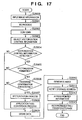
- Fig. 17 is a flowchart for explaining the procedure for an image process which handles password-protected vectorization control information.
- Steps S2000 to S2005 in Fig. 17 are the same as those in the above-mentioned flowchart of Fig. 3 except that information to be detected in the vectorization control information detection step (step S1203) includes a password in addition to vectorization permission/inhibition information. For this reason, even if a scanned document image is determined in step S2005 to be image information which can be vectorized, this embodiment requires the operator in step S2006 to input a password. If the input password does not coincide with a detected password (NO), vectorization is determined to be inhibited, and the flow branches to step S2009. The image is stored as image data. In other words, in this embodiment, the operator who is authorized to execute the vectorization process is limited to those who know a password, thereby improving the maintainability of image information.
- password-protected vectorization control information can be used for another purpose. For example, only an operator who knows the password may be allowed to arbitrarily select whether to inhibit vectorization, thereby increasing the flexibility of the system.
- FIG. 1 An image processing system and image processing method according to the second embodiment of the present invention will be described.
- the arrangement of the image processing system according to the second embodiment is shown in the block diagram of Fig. 1 , similarly to the first embodiment.
- An MFP 100 is the same as that shown in Fig. 2 .
- control of inhibition/permission of vectorization is not set independently for each page but for each of a plurality of objects obtained by block selection. This arrangement makes it possible to further increase the convenience of vectorization.
- Vectorization control information for each of objects in a page can be set by the operator using a key operation unit equipped on the MFP 100.
- Fig. 18 is a flowchart for explaining the procedure for a vectorization control setting process for each object by the key operation unit equipped on the MFP 100.
- the vectorization control setting process will be described with reference to Fig. 18 .
- step S2101 It is first determined whether an image to be output has vectorization control information (step S2101). If no vectorization control information is detected (NO), the flow branches to step S2102. In step S2102, a condition set by the operator as to whether to execute vectorization control is determined. If the vectorization control is necessary (YES), vectorization control information is set and generated in step S2103 and subsequent steps.
- step S2102 determines whether vectorization control information is unnecessary (NO) or not. If it is determined in step S2102 that vectorization control information is unnecessary (NO), an image is directly output in step S2109 without appending the vectorization control information in step S2108. If the image to be output has any vectorization control information in step S2101 (YES), the flow directly advances to the vectorization control information appending process in step S2108. The vectorization control information is appended to the image, and in an output step (step S2109), the image appended with the vectorization control information is output.
- Fig. 19 is a view showing an example of a copy basic window of the key operation unit of the MFP 100. Since a function as described here is often placed in an inner layer by one level in this embodiment, the function is classified as one function of an "application mode".
- Fig. 20 is a view showing an example of an application mode window of the key operation unit of the MFP 100.
- a Vectorize key 1001 indicates a function that pertains to vectorization control information setting.
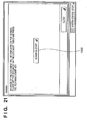
- a window shown in Fig. 21 is displayed.
- Fig. 21 is a view showing an example of a Vectorize window of the key operation unit of the MFP 100.
- the image scanning unit 110 scans a set document, and a window as shown in Fig. 22 is displayed on the key operation unit.
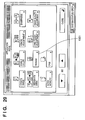
- Fig. 22 is a view showing an example of a window after image scanning on the key operation unit of the MFP 100.
- a scanned image and a result obtained by dividing image information in block selection are displayed in frames as indicated by reference numeral 1010.
- a block selection process can be executed in the same manner as in the above-mentioned embodiment.
- the properties and positions of objects constituting the display screen are represented by, e.g., colors and rectangles.
- An image can be displayed as a reduced image.
- An enlargement/reduction key 1011 can increase/reduce a display image to an arbitrary size. A portion which exceeds the display area due to enlargement can be viewed by scrolling across and down using a scroll button 1012.
- an object is selected (step S2104).
- a text object containing a character string "We are always waiting YOU!” at the center is selected.
- the object is enclosed in a red solid frame while the remaining objects are enclosed in dashed frames of colors indicating their properties.
- a text object can be represented by red; a graphic object, blue; a table object, green; and an image object, yellow.
- the remaining object can be represented as a background object.
- the background object is an image portion left after extracting the objects constituting the image and is not enclosed in a rectangular frame.
- any page can be selected using page selection buttons 1015.
- the image and a block selection result of the page are displayed in the frames 1010.
- step S2105 of setting vectorization control information as to whether to permit vectorization of a selected object is determined by a Vectorize key 1016. More specifically, if setting is permitted, the Vectorize key 1016 is highlighted; otherwise, the Vectorize key 1016 is normally displayed. In the case shown in Fig. 22 , vectorization of a selected object is not permitted.
- an OK key 1017 is pressed, a setting having been made up to that time is saved as the vectorization control information.
- a setting cancel key 1018 is pressed, a setting having been made up to that time is discarded, and the window returns to the copy basic window shown in Fig. 19 .
- vectorization control information setting of the object of interest ends. If the operator wants to make the same setting for another object, the flow branches in step S2106 and returns to the object selection step in step S2104 to repeat the setting operation. After the vectorization control information setting ends, steps S2107 to S2109 output data.
- the vectorization control information thus saved for each object is encoded as a data sequence of control information in a two-dimensional barcode generated and appended for each document image in the above-mentioned embodiment and is appended to an output image.
- a two-dimensional barcode is appended in the same manner as in the above-mentioned embodiment.
- a method of directly appending a character string in a document or a so-called watermarking method including a method of embedding information by modulating the spacings of a character string in a document (especially, the spacings between neighboring characters), a method of embedding information in a halftone image in a document, and the like may be adopted.
- FIG. 23 is a flowchart for explaining the procedure for an image process which handles password-protected vectorization control information.
- Steps S2300 to S2307 in Fig. 23 are the same as steps S2000 to S2007 in Fig. 17 described as another example of the first embodiment except that information to be detected in the vectorization control information detection step (step S1203) includes a password in addition to vectorization permission/inhibition-information. Even if a scanned document image is determined in step S2305 to be image information which can be vectorized, this embodiment requires the operator in step S2306 to input a password. If the input password does not coincide with a detected password (NO), vectorization is determined to be inhibited, and the flow branches to step S2310. The image is stored as image data.
- step S2308 When the vectorization process in step S2307 ends for one object, it is determined in step S2308 whether all objects in a page have been processed. If any more object to be vectorized remains, the processes from step S2305 are repeated for the next object. In other words, in this embodiment, the operator who is authorized to execute the vectorization process is limited to those who know a password. This makes it possible to improve the maintainability of image information and execute advanced control of the re-use of electronified data.
- password-protected vectorization control information can be used for another purpose. For example, only an operator who knows the password may be allowed to arbitrarily select whether to inhibit vectorization, thereby increasing the flexibility of the system.
- object control information includes object feature information (e.g., containing a specific character string, having a specific shape, or the like) which inhibits vectorization, control of inhibition/permission of vectorization for an object having a specific feature is allowed.
- object feature information e.g., containing a specific character string, having a specific shape, or the like
- vectorization control information includes the layout information of objects in a document
- an object to be subjected to vectorization control can be designated in the layout information. This results in higher-precision control of inhibition/permission of vectorization.
- the present invention can be applied to an apparatus comprising a single device or to system constituted by a plurality of devices.
- the invention can be implemented by supplying a software program, which implements the functions of the foregoing embodiments, directly or indirectly to a system or apparatus, reading the supplied program code with a computer of the system or apparatus, and then executing the program code.
- a software program which implements the functions of the foregoing embodiments
- reading the supplied program code with a computer of the system or apparatus, and then executing the program code.
- the mode of implementation need not rely upon a program.
- the program code installed in the computer also implements the present invention.
- the claims of the present invention also cover a computer program for the purpose of implementing the functions of the present invention.
- the program may be executed in any form, such as an object code, a program executed by an interpreter, or scrip data supplied to an operating system.
- Example of storage media that can be used for supplying the program are a floppy disk, a hard disk, an optical disk, a magneto-optical disk, a CD-ROM, a CD-R, a CD-RW, a magnetic tape, a non-volatile type memory card, a ROM, and a DVD (DVD-ROM and a DVD-R).
- a client computer can be connected to a website on the Internet using a browser of the client computer, and the computer program of the present invention or an automatically-installable compressed file of the program can be downloaded to a recording medium such as a hard disk.
- the program of the present invention can be supplied by dividing the program code constituting the program into a plurality of files and downloading the files from different websites.
- a WWW World Wide Web
- a storage medium such as a CD-ROM
- an operating system or the like running on the computer may perform all or a part of the actual processing so that the functions of the foregoing embodiments can be implemented by this processing.
- a CPU or the like mounted on the function expansion board or function expansion unit performs all or a part of the actual processing so that the functions of the foregoing embodiments can be implemented by this processing.
- whether to convert an original paper document into re-usable vector data before obtaining vector data from the paper document can appropriately be set.
Landscapes
- Business, Economics & Management (AREA)
- Engineering & Computer Science (AREA)
- Theoretical Computer Science (AREA)
- Tourism & Hospitality (AREA)
- General Physics & Mathematics (AREA)
- Economics (AREA)
- Marketing (AREA)
- Strategic Management (AREA)
- Technology Law (AREA)
- Physics & Mathematics (AREA)
- General Business, Economics & Management (AREA)
- Accounting & Taxation (AREA)
- Finance (AREA)
- Health & Medical Sciences (AREA)
- Development Economics (AREA)
- General Health & Medical Sciences (AREA)
- Human Resources & Organizations (AREA)
- Primary Health Care (AREA)
- Multimedia (AREA)
- Signal Processing (AREA)
- Processing Or Creating Images (AREA)
- Editing Of Facsimile Originals (AREA)
- Facsimile Image Signal Circuits (AREA)
- Image Processing (AREA)
Claims (7)
- Bildverarbeitungssystem, umfassend:eine Leseeinrichtung (110) zum Lesen eines Dokuments, um Bildinformation zu erhalten;eine Speichereinrichtung (111) zum Speichern der Bildinformation;eine Vektorisiereinrichtung zum Vektorisieren der von der Leseeinrichtung erhaltenen Bildinformation;dadurch gekennzeichnet, dass es weiter umfasst:eine Aufteilungseinrichtung zum Aufteilen der von der Leseeinrichtung erhaltenen Bildinformation in mehrere Objekte (42);eine Detektoreinrichtung zum Detektieren (S1203) von in das Dokument eingebetteter Steuerinformation aus der von der Leseeinrichtung erhaltenen Bildinformation;eine Bestimmungseinrichtung, um für jedes der Objekte basierend auf der von der Detektoreinrichtung detektierten Steuerinformation zu bestimmen (S1205), ob eine Vektorisierung der von der Leseeinrichtung erhaltenen Bildinformation erlaubt oder verboten ist; undeine Steuereinrichtung, um in der Speichereinrichtung die von der Leseeinrichtung erhaltene Bildinformation anstelle der Vektordaten zu speichern (S1208), welche von der Vektorisiereinrichtung vektorisiert wurden, wenn nicht die Detektoreinrichtung die Steuerinformation detektiert, um die Vektorisiereinrichtung zu veranlassen, die Bildinformation eines Objekts in Vektordaten umzuwandeln, wenn die Bestimmungseinrichtung bestimmt, dass eine Vektorisierung der Bildinformation des Objekts erlaubt ist, und um in der Speichereinrichtung die von der Leseeinrichtung erhaltene Bildinformation anstelle der von der Vektorisiereinrichtung vektorisierten Vektordaten zu speichern, wenn die Bestimmungseinrichtung bestimmt, dass eine Vektorisierung der Bildinformation verboten ist.
- System nach Anspruch 1, dadurch gekennzeichnet, dass es weiterhin umfasst:eine Zeichenerkennungseinrichtung zum Ausführen einer Zeichencodeumwandlung für die Bildinformation,dadurch gekennzeichnet, dass, wenn die Bestimmungseinrichtung bestimmt, dass eine Zeichencodeumwandlung der Bildinformation nicht verboten ist, die Steuereinrichtung die Zeichenerkennungseinrichtung veranlasst, eine Zeichencodeumwandlung für die Bildinformation auszuführen.
- System nach Anspruch 1, dadurch gekennzeichnet, dass es weiterhin umfasst:eine Bildumwandlungseinrichtung zum Umwandeln der Bildinformation in ein vorbestimmtes Bildformat,dadurch gekennzeichnet, dass, wenn die Bestimmungseinrichtung bestimmt, dass die Bildumwandlung der Bildinformation in das vorbestimmte Format nicht verboten ist, die Steuereinrichtung die Bildumwandlungseinrichtung veranlasst, die Bildumwandlung für die Bildinformation auszuführen.
- System nach Anspruch 1, dadurch gekennzeichnet, dass es weiterhin umfasst:eine Extrahiereinrichtung zum Extrahieren von Benutzerauthentifizierungsinformation aus der Steuerinformation;eine Anforderungseinrichtung zum Anfordern einer Eingabe der Benutzerauthentifizierungsinformation, bevor eine Vektorisierung der Bildinformation durch die Vektorisiereinrichtung erfolgt; undeine Zuordnungseinrichtung zum Zuordnen von eingegebener Benutzerauthentifizierinformation mit durch die Extrahiereinrichtung extrahierter Benutzerauthentifizierinformation,dadurch gekennzeichnet, dass die Steuereinrichtung der Vektorisiereinrichtung erlaubt, die Bildinformation in Vektordaten umzuwandeln auf der Basis eines Ergebnisses, wonach eine Benutzerauthentifizierungsinformation durch die Zuordnungseinrichtung als übereinstimmend ermittelt wird.
- Bildverarbeitungsverfahren, umfassend:einen Leseschritt zum Lesen eines Dokuments, um Bildinformation zu erhalten;einen Speicherschritt zum Speichern der Bildinformation in einer Speichereinrichtung (111);einen Vektorisierschritt zum Vektorisieren der im Leseschritt erhaltenen Bildinformation;dadurch gekennzeichnet, dass es weiter umfasst:einen Aufteilungsschritt zum Aufteilen der im Leseschritt erhaltenen Bildinformation in mehrere Objekte (42);einen Detektierschritt zum Detektieren (S1203) von in das Dokument eingebetteter Steuerinformation aus der im Leseschritt erhaltenen Bildinformation;einen Bestimmungsschritt, um für jedes der Objekte basierend auf der im Detektierschritt detektierten Steuerinformation zu bestimmen (S1205), ob eine Vektorisierung der im Leseschritt erhaltenen Bildinformation erlaubt oder verboten ist; undeinen Steuerschritt zum Speichern (S1208) der im Leseschritt erhaltenen Bildinformation in der Speichereinrichtung anstelle der im Vektorisierschritt vektorisierten Vektordaten, wenn nicht im Detektierschritt die Steuerinformation detektiert wird, zum Umwandeln der Bildinformation eines Objekts in Vektordaten im Vektorisierschritt, wenn im Bestimmungsschritt bestimmt wird, dass eine Vektorisierung der Bildinformation des Objekts erlaubt ist, und zum Speichern der im Leseschritt erhaltenen Bildinformation anstelle der im Vektorisierschritt vektorisierten Vektordaten, wenn im Bestimmungsschritt bestimmt wird, dass eine Vektorisierung der Bildinformation verboten ist.
- Programm zum Veranlassen eines Computers, folgendes auszuführen:eine Leseprozedur zum Lesen eines Dokuments, um Bildinformation zu erhalten;eine Speicherprozedur zum Speichern der Bildinformation in einer Speichereinrichtung (111);eine Vektorisierprozedur zum Vektorisieren der durch die Leseprozedur erhaltenen Bildinformation;dadurch gekennzeichnet, dass es weiter umfasst:eine Aufteilungsprozedur zum Aufteilen der durch die Leseprozedur erhaltenen Bildinformation in mehrere Objekte;eine Detektierprozedur (S1203) zum Detektieren von in das Dokument eingebetteter Steuerinformation aus der durch die Leseprozedur erhaltenen Bildinformation;eine Bestimmungsprozedur, um für jedes der Objekte basierend auf der von der Detektierprozedur detektierten Steuerinformation zu bestimmen, ob eine Vektorisierung der durch die Leseprozedur erhaltenen Bildinformation erlaubt oder verboten ist; undeine Steuerprozedur, um in der Speichereinrichtung die durch die Leseprozedur erhaltene Bildinformation anstelle der durch die Vektorisierprozedur vektorisierten Vektordaten zu speichern (S1208), wenn nicht die Detektierprozedur die Steuerinformation detektiert, um die Bildinformation eines Objekts in Vektordaten in der Vektorisierprozedur umzuwandeln, wenn in der Bestimmungsprozedur bestimmt wird, dass eine Vektorisierung der Bildinformation des Objekts erlaubt ist, und um die durch die Leseprozedur erhaltene Bildinformation anstelle der durch die Vektorisierprozedur vektorisierten Vektordaten zu speichern, wenn in der Bestimmungsprozedur bestimmt wird, dass eine Vektorisierung der Bildinformation verboten ist.
- Computerlesbarer Aufzeichnungsträger, gekennzeichnet durch Speicherung eines Programms gemäß Anspruch 6.
Applications Claiming Priority (2)
| Application Number | Priority Date | Filing Date | Title |
|---|---|---|---|
| JP2003407770 | 2003-12-05 | ||
| JP2003407770A JP3997198B2 (ja) | 2003-12-05 | 2003-12-05 | 画像処理システム及び画像処理方法 |
Publications (3)
| Publication Number | Publication Date |
|---|---|
| EP1538564A2 EP1538564A2 (de) | 2005-06-08 |
| EP1538564A3 EP1538564A3 (de) | 2006-03-29 |
| EP1538564B1 true EP1538564B1 (de) | 2012-05-09 |
Family
ID=34464028
Family Applications (1)
| Application Number | Title | Priority Date | Filing Date |
|---|---|---|---|
| EP04257455A Expired - Lifetime EP1538564B1 (de) | 2003-12-05 | 2004-12-01 | Bildverarbeitungssystem und Bildverarbeitungsverfahren |
Country Status (4)
| Country | Link |
|---|---|
| US (1) | US7421124B2 (de) |
| EP (1) | EP1538564B1 (de) |
| JP (1) | JP3997198B2 (de) |
| CN (1) | CN100367750C (de) |
Families Citing this family (26)
| Publication number | Priority date | Publication date | Assignee | Title |
|---|---|---|---|---|
| JP4208780B2 (ja) * | 2004-07-07 | 2009-01-14 | キヤノン株式会社 | 画像処理システム及び画像処理装置の制御方法並びにプログラム |
| JP2006023944A (ja) | 2004-07-07 | 2006-01-26 | Canon Inc | 画像処理システム及び画像処理方法 |
| JP4227569B2 (ja) * | 2004-07-07 | 2009-02-18 | キヤノン株式会社 | 画像処理システム、画像処理装置の制御方法、プログラム及び記録媒体 |
| JP2006023945A (ja) * | 2004-07-07 | 2006-01-26 | Canon Inc | 画像処理システム及び画像処理方法 |
| JP2006025129A (ja) * | 2004-07-07 | 2006-01-26 | Canon Inc | 画像処理システム及び画像処理方法 |
| JP4408836B2 (ja) * | 2005-05-30 | 2010-02-03 | キヤノン株式会社 | 画像処理装置及びその制御方法、プログラム |
| JP4661525B2 (ja) * | 2005-10-26 | 2011-03-30 | コニカミノルタビジネステクノロジーズ株式会社 | 画像処理装置、画像処理方法、および画像処理プログラム |
| US20070133031A1 (en) * | 2005-12-08 | 2007-06-14 | Canon Kabushiki Kaisha | Image processing apparatus and image processing method |
| JP2007299321A (ja) * | 2006-05-02 | 2007-11-15 | Ricoh Co Ltd | 情報処理装置、情報処理方法、情報処理プログラム、及び、情報記憶媒体 |
| US8175394B2 (en) * | 2006-09-08 | 2012-05-08 | Google Inc. | Shape clustering in post optical character recognition processing |
| JP4498375B2 (ja) | 2007-03-22 | 2010-07-07 | キヤノン株式会社 | 出力装置、出力方法、出力システム、およびプログラム |
| US8233719B2 (en) * | 2007-12-20 | 2012-07-31 | Ati Technologies Ulc | Method and apparatus for determining image content |
| US8751480B1 (en) * | 2008-01-31 | 2014-06-10 | The Mathworks, Inc. | Virtual arrays in an array-based language |
| US20090196529A1 (en) * | 2008-02-06 | 2009-08-06 | William Su | System and method for content sensitive document processing |
| JP5132347B2 (ja) * | 2008-02-13 | 2013-01-30 | キヤノン株式会社 | 画像処理システム |
| JP2009218711A (ja) * | 2008-03-07 | 2009-09-24 | Canon Inc | 情報処理装置、画像処理装置、情報処理装置の制御方法、画像処理装置の制御方法、及び、プログラム |
| US20090244558A1 (en) * | 2008-03-25 | 2009-10-01 | Kabushiki Kaisha Toshiba | Image processing apparatus and image processing method |
| JP5377044B2 (ja) * | 2009-04-14 | 2013-12-25 | キヤノン株式会社 | 印刷システム、データ処理方法およびプログラム |
| US9721237B2 (en) | 2011-06-24 | 2017-08-01 | Paypal, Inc. | Animated two-dimensional barcode checks |
| JP4900529B1 (ja) * | 2011-09-12 | 2012-03-21 | 富士ゼロックス株式会社 | 画像処理装置及びプログラム |
| JP5936381B2 (ja) | 2012-02-09 | 2016-06-22 | キヤノン株式会社 | 画像処理装置及びその制御方法とプログラム |
| JP6000992B2 (ja) * | 2014-01-24 | 2016-10-05 | 京セラドキュメントソリューションズ株式会社 | 文書ファイル生成装置及び文書ファイル生成方法 |
| JP2018136654A (ja) * | 2017-02-21 | 2018-08-30 | 富士ゼロックス株式会社 | 画像処理装置及び画像処理プログラム |
| CN111339803B (zh) * | 2018-12-19 | 2023-10-24 | 新方正控股发展有限责任公司 | 字体识别方法、装置、设备及计算机可读存储介质 |
| WO2023012959A1 (ja) * | 2021-08-05 | 2023-02-09 | 三菱電機株式会社 | プログラマブルコントローラ、プログラマブルコントローラシステム及びプログラム |
| JP2023176412A (ja) | 2022-05-31 | 2023-12-13 | シャープ株式会社 | 画像出力装置、画像出力方法及びプログラム |
Family Cites Families (12)
| Publication number | Priority date | Publication date | Assignee | Title |
|---|---|---|---|---|
| US4908873A (en) * | 1983-05-13 | 1990-03-13 | Philibert Alex C | Document reproduction security system |
| US4817187A (en) * | 1987-02-19 | 1989-03-28 | Gtx Corporation | Apparatus and method for vectorization of incoming scanned image data |
| US4935821A (en) * | 1987-08-13 | 1990-06-19 | Ricoh Company, Ltd. | Image processing apparatus for multi-media copying machine |
| JP2930612B2 (ja) * | 1989-10-05 | 1999-08-03 | 株式会社リコー | 画像形成装置 |
| JPH0512402A (ja) | 1991-07-05 | 1993-01-22 | Ricoh Co Ltd | 電子フアイルシステムの文字編集処理方法 |
| JPH06178100A (ja) | 1992-12-11 | 1994-06-24 | Minolta Camera Co Ltd | 画像処理装置 |
| JP4071328B2 (ja) * | 1997-11-18 | 2008-04-02 | 富士通株式会社 | 文書画像処理装置および方法 |
| US6487301B1 (en) * | 1998-04-30 | 2002-11-26 | Mediasec Technologies Llc | Digital authentication with digital and analog documents |
| WO2001071960A1 (en) * | 2000-03-18 | 2001-09-27 | Digimarc Corporation | Transmarking, watermark embedding functions as rendering commands, and feature-based watermarking of multimedia signals |
| US20030210803A1 (en) * | 2002-03-29 | 2003-11-13 | Canon Kabushiki Kaisha | Image processing apparatus and method |
| US20040151377A1 (en) * | 2003-02-04 | 2004-08-05 | Boose Molly L. | Apparatus and methods for converting network drawings from raster format to vector format |
| KR100747879B1 (ko) * | 2004-06-10 | 2007-08-08 | 캐논 가부시끼가이샤 | 화상 처리 장치, 제어 방법 및 기록 매체 |
-
2003
- 2003-12-05 JP JP2003407770A patent/JP3997198B2/ja not_active Expired - Fee Related
-
2004
- 2004-12-01 EP EP04257455A patent/EP1538564B1/de not_active Expired - Lifetime
- 2004-12-03 CN CNB2004100983470A patent/CN100367750C/zh not_active Expired - Fee Related
- 2004-12-03 US US11/002,120 patent/US7421124B2/en not_active Expired - Fee Related
Also Published As
| Publication number | Publication date |
|---|---|
| US7421124B2 (en) | 2008-09-02 |
| EP1538564A3 (de) | 2006-03-29 |
| CN100367750C (zh) | 2008-02-06 |
| EP1538564A2 (de) | 2005-06-08 |
| US20050123209A1 (en) | 2005-06-09 |
| CN1627786A (zh) | 2005-06-15 |
| JP3997198B2 (ja) | 2007-10-24 |
| JP2005167937A (ja) | 2005-06-23 |
Similar Documents
| Publication | Publication Date | Title |
|---|---|---|
| EP1538564B1 (de) | Bildverarbeitungssystem und Bildverarbeitungsverfahren | |
| US8339619B2 (en) | System and image processing method and apparatus for re-using and re-editing images | |
| US7593120B2 (en) | Image processing apparatus, control method therefor, and program | |
| US7681121B2 (en) | Image processing apparatus, control method therefor, and program | |
| US7542605B2 (en) | Image processing apparatus, control method therefor, and program | |
| EP1588293B1 (de) | Bildverarbeitungsverfahrensystemprogramm, programmspeichermediumund informationsverarbeitungsvorrichtung | |
| US7532757B2 (en) | Image processing apparatus, control method therefor, and program | |
| US7317833B2 (en) | Image processing apparatus and image processing method | |
| US7640269B2 (en) | Image processing system and image processing method | |
| EP1455284A2 (de) | Bildverarbeitungsverfahren und Bildverarbeitungssystem | |
| EP1533745B1 (de) | Bildverarbeitungsanordnung, dafür geeignetes Steuerungsverfahren sowie Programm | |
| US7551753B2 (en) | Image processing apparatus and method therefor | |
| US20060008113A1 (en) | Image processing system and image processing method | |
| JP4338189B2 (ja) | 画像処理システム及び画像処理方法 | |
| US7596271B2 (en) | Image processing system and image processing method | |
| JP2005149097A (ja) | 画像処理システム及び画像処理方法 | |
| JP2005174227A (ja) | 画像処理装置及びその制御方法、プログラム | |
| JP2005149098A (ja) | 画像処理システム及び画像処理装置並びに画像処理方法 | |
| JP2005157447A (ja) | 画像処理システム及び画像処理方法 | |
| JP2005165674A (ja) | 画像処理装置、画像処理方法、及びコンピュータプログラム | |
| JP2006148663A (ja) | 画像処理システム | |
| JP2006195887A (ja) | 画像処理システム |
Legal Events
| Date | Code | Title | Description |
|---|---|---|---|
| PUAI | Public reference made under article 153(3) epc to a published international application that has entered the european phase |
Free format text: ORIGINAL CODE: 0009012 |
|
| AK | Designated contracting states |
Kind code of ref document: A2 Designated state(s): AT BE BG CH CY CZ DE DK EE ES FI FR GB GR HU IE IS IT LI LT LU MC NL PL PT RO SE SI SK TR |
|
| AX | Request for extension of the european patent |
Extension state: AL BA HR LV MK YU |
|
| PUAL | Search report despatched |
Free format text: ORIGINAL CODE: 0009013 |
|
| AK | Designated contracting states |
Kind code of ref document: A3 Designated state(s): AT BE BG CH CY CZ DE DK EE ES FI FR GB GR HU IE IS IT LI LT LU MC NL PL PT RO SE SI SK TR |
|
| AX | Request for extension of the european patent |
Extension state: AL BA HR LV MK YU |
|
| RIC1 | Information provided on ipc code assigned before grant |
Ipc: G06T 5/00 20060101AFI20050406BHEP Ipc: H04N 1/40 20060101ALI20060209BHEP Ipc: H04N 1/41 20060101ALI20060209BHEP |
|
| 17P | Request for examination filed |
Effective date: 20060929 |
|
| AKX | Designation fees paid |
Designated state(s): DE FR GB IT |
|
| 17Q | First examination report despatched |
Effective date: 20061215 |
|
| GRAP | Despatch of communication of intention to grant a patent |
Free format text: ORIGINAL CODE: EPIDOSNIGR1 |
|
| GRAS | Grant fee paid |
Free format text: ORIGINAL CODE: EPIDOSNIGR3 |
|
| GRAA | (expected) grant |
Free format text: ORIGINAL CODE: 0009210 |
|
| AK | Designated contracting states |
Kind code of ref document: B1 Designated state(s): DE FR GB IT |
|
| REG | Reference to a national code |
Ref country code: GB Ref legal event code: FG4D |
|
| REG | Reference to a national code |
Ref country code: DE Ref legal event code: R096 Ref document number: 602004037727 Country of ref document: DE Effective date: 20120705 |
|
| PG25 | Lapsed in a contracting state [announced via postgrant information from national office to epo] |
Ref country code: IT Free format text: LAPSE BECAUSE OF FAILURE TO SUBMIT A TRANSLATION OF THE DESCRIPTION OR TO PAY THE FEE WITHIN THE PRESCRIBED TIME-LIMIT Effective date: 20120509 |
|
| PLBE | No opposition filed within time limit |
Free format text: ORIGINAL CODE: 0009261 |
|
| STAA | Information on the status of an ep patent application or granted ep patent |
Free format text: STATUS: NO OPPOSITION FILED WITHIN TIME LIMIT |
|
| 26N | No opposition filed |
Effective date: 20130212 |
|
| REG | Reference to a national code |
Ref country code: DE Ref legal event code: R097 Ref document number: 602004037727 Country of ref document: DE Effective date: 20130212 |
|
| PGFP | Annual fee paid to national office [announced via postgrant information from national office to epo] |
Ref country code: GB Payment date: 20131217 Year of fee payment: 10 Ref country code: DE Payment date: 20131231 Year of fee payment: 10 |
|
| PGFP | Annual fee paid to national office [announced via postgrant information from national office to epo] |
Ref country code: FR Payment date: 20131227 Year of fee payment: 10 |
|
| REG | Reference to a national code |
Ref country code: DE Ref legal event code: R119 Ref document number: 602004037727 Country of ref document: DE |
|
| GBPC | Gb: european patent ceased through non-payment of renewal fee |
Effective date: 20141201 |
|
| REG | Reference to a national code |
Ref country code: FR Ref legal event code: ST Effective date: 20150831 |
|
| PG25 | Lapsed in a contracting state [announced via postgrant information from national office to epo] |
Ref country code: DE Free format text: LAPSE BECAUSE OF NON-PAYMENT OF DUE FEES Effective date: 20150701 Ref country code: GB Free format text: LAPSE BECAUSE OF NON-PAYMENT OF DUE FEES Effective date: 20141201 |
|
| PG25 | Lapsed in a contracting state [announced via postgrant information from national office to epo] |
Ref country code: FR Free format text: LAPSE BECAUSE OF NON-PAYMENT OF DUE FEES Effective date: 20141231 |