EP1538403A2 - Absorbeur solaire en forme de plaque et son procédé de fabrication - Google Patents
Absorbeur solaire en forme de plaque et son procédé de fabrication Download PDFInfo
- Publication number
- EP1538403A2 EP1538403A2 EP04028281A EP04028281A EP1538403A2 EP 1538403 A2 EP1538403 A2 EP 1538403A2 EP 04028281 A EP04028281 A EP 04028281A EP 04028281 A EP04028281 A EP 04028281A EP 1538403 A2 EP1538403 A2 EP 1538403A2
- Authority
- EP
- European Patent Office
- Prior art keywords
- absorber
- tubes
- plate
- shaped radiation
- tube
- Prior art date
- Legal status (The legal status is an assumption and is not a legal conclusion. Google has not performed a legal analysis and makes no representation as to the accuracy of the status listed.)
- Withdrawn
Links
- 239000006096 absorbing agent Substances 0.000 title claims abstract description 150
- 238000000034 method Methods 0.000 title claims abstract description 52
- 239000006100 radiation absorber Substances 0.000 claims abstract description 58
- 238000004519 manufacturing process Methods 0.000 claims abstract description 6
- 238000005304 joining Methods 0.000 claims description 18
- XLYOFNOQVPJJNP-UHFFFAOYSA-N water Substances O XLYOFNOQVPJJNP-UHFFFAOYSA-N 0.000 claims description 14
- 210000002445 nipple Anatomy 0.000 claims description 12
- 238000005476 soldering Methods 0.000 claims description 12
- 238000003466 welding Methods 0.000 claims description 12
- 239000000463 material Substances 0.000 claims description 9
- RYGMFSIKBFXOCR-UHFFFAOYSA-N Copper Chemical compound [Cu] RYGMFSIKBFXOCR-UHFFFAOYSA-N 0.000 claims description 6
- 239000011248 coating agent Substances 0.000 claims description 6
- 238000000576 coating method Methods 0.000 claims description 6
- 229910052802 copper Inorganic materials 0.000 claims description 6
- 239000010949 copper Substances 0.000 claims description 6
- 239000007769 metal material Substances 0.000 claims description 4
- 238000007493 shaping process Methods 0.000 claims description 3
- 238000012546 transfer Methods 0.000 description 8
- 239000002131 composite material Substances 0.000 description 3
- 239000007788 liquid Substances 0.000 description 3
- 238000012549 training Methods 0.000 description 3
- 238000011161 development Methods 0.000 description 2
- 230000018109 developmental process Effects 0.000 description 2
- 239000002184 metal Substances 0.000 description 2
- 229910052751 metal Inorganic materials 0.000 description 2
- 238000005240 physical vapour deposition Methods 0.000 description 2
- 238000010521 absorption reaction Methods 0.000 description 1
- 230000002411 adverse Effects 0.000 description 1
- 239000011324 bead Substances 0.000 description 1
- 230000001419 dependent effect Effects 0.000 description 1
- 238000013461 design Methods 0.000 description 1
- 238000010894 electron beam technology Methods 0.000 description 1
- 230000008020 evaporation Effects 0.000 description 1
- 238000001704 evaporation Methods 0.000 description 1
- 238000010438 heat treatment Methods 0.000 description 1
- 238000009434 installation Methods 0.000 description 1
- 239000004922 lacquer Substances 0.000 description 1
- 239000002244 precipitate Substances 0.000 description 1
- 238000002360 preparation method Methods 0.000 description 1
- 230000001681 protective effect Effects 0.000 description 1
- 238000004080 punching Methods 0.000 description 1
- 230000005855 radiation Effects 0.000 description 1
- 229910000679 solder Inorganic materials 0.000 description 1
- 238000004544 sputter deposition Methods 0.000 description 1
- 239000007858 starting material Substances 0.000 description 1
- 238000003860 storage Methods 0.000 description 1
- 238000012360 testing method Methods 0.000 description 1
- 230000009466 transformation Effects 0.000 description 1
- 239000012808 vapor phase Substances 0.000 description 1
Images



Classifications
-
- F—MECHANICAL ENGINEERING; LIGHTING; HEATING; WEAPONS; BLASTING
- F24—HEATING; RANGES; VENTILATING
- F24S—SOLAR HEAT COLLECTORS; SOLAR HEAT SYSTEMS
- F24S10/00—Solar heat collectors using working fluids
- F24S10/70—Solar heat collectors using working fluids the working fluids being conveyed through tubular absorbing conduits
- F24S10/75—Solar heat collectors using working fluids the working fluids being conveyed through tubular absorbing conduits with enlarged surfaces, e.g. with protrusions or corrugations
- F24S10/753—Solar heat collectors using working fluids the working fluids being conveyed through tubular absorbing conduits with enlarged surfaces, e.g. with protrusions or corrugations the conduits being parallel to each other
-
- Y—GENERAL TAGGING OF NEW TECHNOLOGICAL DEVELOPMENTS; GENERAL TAGGING OF CROSS-SECTIONAL TECHNOLOGIES SPANNING OVER SEVERAL SECTIONS OF THE IPC; TECHNICAL SUBJECTS COVERED BY FORMER USPC CROSS-REFERENCE ART COLLECTIONS [XRACs] AND DIGESTS
- Y02—TECHNOLOGIES OR APPLICATIONS FOR MITIGATION OR ADAPTATION AGAINST CLIMATE CHANGE
- Y02E—REDUCTION OF GREENHOUSE GAS [GHG] EMISSIONS, RELATED TO ENERGY GENERATION, TRANSMISSION OR DISTRIBUTION
- Y02E10/00—Energy generation through renewable energy sources
- Y02E10/40—Solar thermal energy, e.g. solar towers
- Y02E10/44—Heat exchange systems
Definitions
- the invention relates to a plate-shaped radiation absorber and a method to its preparation according to the preamble of claim 1 and 21, respectively.
- Heat exchangers in the form of plate-shaped radiation absorbers have been known for some time.
- a plurality of absorber tubes arranged at a distance from each other are arranged on a largely planar absorber plate, which in turn are connected via connecting sections formed by the absorber plate.
- the absorber tubes serve to receive, for example, a liquid heat transfer medium, such as water, and are also connected to so-called collecting pipes (supply, return).
- the absorber tubes are here prefabricated by defined material deformation of an output board and subsequent waterproof and / or airtight joining the joint joints of the same and then firmly connected to the absorber sheet by soldering or welding.
- Predominantly absorber tubes are welded by means of a longitudinal seam on a corresponding absorber plate or soldered.
- the object of the invention is to provide a plate-shaped radiation absorber, which compared to conventional improved efficiency, easy in the production and, accordingly, is inexpensive and an improved look has its visible surface.
- the two adjacent edge webs between them a connecting web of a separate manufactured absorber tube in the form of a preformed or already finished molded as well as water and / or airtight to a closed in cross-section
- a connecting web of a separate manufactured absorber tube in the form of a preformed or already finished molded as well as water and / or airtight to a closed in cross-section Include hollow profile joined absorber tube and attached to this.
- a second preferred embodiment of the invention provides that at least one Edge web of a connecting portion to a one-piece with the connecting portion trained preformed or fully formed as well as and / or airtight to a closed cross-section hollow profile absorber tube molded with connecting bar and firmly connected to the adjacent edge web is.
- a third preferred embodiment of the invention form butt to each other joined adjacent edge webs of a web composite, at which a laterally Connecting web of a separately manufactured absorber tube in the form of a preformed or already fully formed as well as water and / or airtight to an im Cross-section closed hollow profile joined absorber tube is attached.
- the shaped absorber tubes preferably in the region of its trained connecting web to a in Cross-section closed hollow profile are joined.
- the transformation of the output boards respectively shaping of the connecting sections and absorber tubes is preferably realized by roll forming, wherein the Surface of the same may be formed largely smooth or contoured.
- the final molded absorber tubes have this largely one Cross-section on the basic geometry of a polygon, an ellipse or on any other basic geometry representing a closed cross-section, preferably However, it is attributed to the basic geometry of a circle.
- the absorber tubes end to common Be connected to manifolds, which in turn have recesses, in which the absorber tubes open.
- the absorber tubes it is also possible in the headers to the absorber tubes to bring in corresponding recesses, which in turn a slot connection for the positive reception of an end portion of the absorber tube together Have connecting web, wherein the absorber tube provided with a flow-through is.
- adjacent absorber tubes can be so be fluidly connected by means nipple elements that a meandering guided absorber tube is formed.
- a joining method for the connection of the absorber tubes with the headers or between each other or via nipple elements is preferably a soldering process at.
- the absorber tubes, connecting sections and / or manifolds exist insofar made of a metal material, preferably of copper.
- the method for producing a plate-shaped radiation absorber with a Plural arranged in a common plane and via connecting sections interconnected as well as through defined material deformation and waterproof and / or airtight joining of joining areas of the formed Material produced absorber tubes, which in turn can be connected to headers are essentially characterized by the fact that the connecting sections as separately manufactured components and each with parallel to the longitudinal axis of the absorber channels directed parked edge webs are formed, where each adjacent edge webs an absorber tube is connected and the connecting sections either via the absorber tube or directly, said plate-shaped Radiation absorber training, be firmly connected.
- the advantages achieved by the invention are with regard to the state of Technique essentially in that a sheet-like connection between the Connecting sections and the absorber tubes was created, in turn improved heat transfer from the connecting sections, which are the relevant have effective absorber surface, and the absorber tubes result. Due to the fact that the plate-shaped radiation absorber Mostükkig is formed, the individual components at different times and at be made separate places and need only in the context of a final production, according to customer requirements to a plate-shaped radiation absorber be completed.
- Fig. 1 shows first a plate-shaped radiation absorber 1, which in turn a plurality arranged in a common plane and via so-called connecting sections 2a, 2b has absorber tubes 3 connected to one another.
- the connecting portions 2a, 2b according to the invention as separately manufactured components and each with parallel to the longitudinal axis the Absorberrohre 3 parked edge webs 4, 5, wherein in each case adjacent edge webs 4, 5, the absorber tube 3 can be connected.
- edge webs 4, 5 in turn can turn at its free end a bend 6, resulting in a higher rigidity of the same results.
- bends 6 suitable in the further joining process in the formal centering of the connecting portions 2a, 2b to assist.
- Both the connecting portions 2a, 2b and the absorber tubes 3 are separated from each other, preferably in each case continuously in one or more forming steps from an output board, in particular from a copper sheet board, formed because copper has a high thermal conductivity and also relatively easy to process.
- an output board in particular from a copper sheet board, formed because copper has a high thermal conductivity and also relatively easy to process.
- the radiation absorber 1 it is also possible to use other metal or non-metallic materials for the radiation absorber 1, provided that it ensures the desired heat transfer capacity.
- Roll forming is suitable as a suitable forming method, with the roll forming tools Can be designed to be displaceable transversely to the passage direction to without additional tool change, for example, different profile widths of Can realize connecting portions 2a, 2b.
- the surface of the connecting portions 2a, 2b may be both convex be formed as well as concave, so that the unavoidable thermal fluctuations during operation of the radiation absorber 1 not lead to dislocation and / or delay.
- a structured surface which may be a surface with beads or bulges provide (not shown in more detail).
- Fig. 3 shows schematically the assembly of the radiation absorber in question 1 according to a first embodiment. Thereafter, the absorber tube 3 is formed with a same in the axial direction extending so-called connecting web 7. The two adjacent edge webs 4, 5 of the connecting portions 2a, 2b take, as already described above, the connecting web 7 between them and are finally attached to the same.
- Fig. 5 is a third embodiment of the assembly between two adjacent ones Edge webs 4, 5 and remove an absorber tube 3, wherein first the two adjacent edge webs 4, 5 of the connecting portions 2a, 2b be firmly connected with each other. This is then the side of the connecting web. 7 the absorber tube 3 connected.
- the absorber tube 3 in turn, as already demonstrated above, by roll forming learn his form, in turn, from a hollow profile and said connecting bar 7 exists. Following this, the cross section still open hollow profile closed in a water and / or airtight manner according to a joining method known per se, Within the scope of extensive tests as joining method, the Welding, preferably TIG welding, has proven particularly useful.
- the joint seam in the region of the trained connecting web 7 educated.
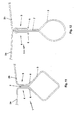
- an output board initially U-shaped shaped (Fig. 7) and finally to a teardrop-shaped hollow profile with connecting web 7 (Fig. 8) are bent.
- the hollow profile by welding, preferably TIG welding, or water and / or soldering hermetically sealed and can subsequently, as described above, with the edge webs 4, 5 of the connecting portions 2a, 2b are connected (Fig. 6).
- the ultrasonic welding As a joining method for firmly connecting the connecting web 7 with the edge webs 4, 5, the ultrasonic welding has proven particularly useful, but others can suitable per se known welding method or soldering for use come and are accordingly covered by the invention.
- the drop-shaped preformed absorber tube 3 can now in its desired final shape, for example a largely circular shape, be transferred in that a so-called internal high-pressure forming process (hydroforming process) is subjected (Fig. 6).
- hydroforming process internal high-pressure forming process
- preformed absorber tubes 3 a plate-shaped Radiation absorber 1 to be converted into their final form.
- subsections of the edge webs 4, 5 also become subjected to a deformation, in this case bent inwardly, whereby this closely conform to the contour of the absorber tube 3 and the overall composite give an additional high rigidity.
- the connecting web 7 of the absorber tube 3 form such an elongated that during the deformation of the preformed absorber tube 3 by means of IHU a deformation of the edge webs 4, 5 is avoided (Fig. 12).
- This particular embodiment of the absorber tube 3 can in particular from Be advantageous if one endeavors, the edge webs 4, 5 with a special contour to provide and not the same by a subsequent deformation, for example due to the above hydroforming process, to be adversely affected.
- one or both of the edge webs 4, 5 may be be formed so advantageous that they are the connecting web 7 of the absorber tube 3 overlap respectively cover.
- this measure is on the Visible surface of the radiation absorber 1 a defined and particularly pleasing edge between the two adjacent connecting sections 2a, 2b of the Radiation absorber 1 created.
- the invention is not limited to circular cross sections of the absorber tube 3, but there will be any suitable closed cross sections detected.
- the absorber tube 3 may have a cross-section or the preformed absorber tube 3 are converted into a cross-section according to the hydroforming process, the on the basic geometry of a polygon (Fig. 9, 10), one on a corner Square (Fig. 11), an ellipse o. A. is due.
- Fig. 12 further shows a drop-shaped cross section of an absorber tube.
- the absorber tubes 3 are in a heating circuit or a flow circuit a heat pump involved, where they each end to common Collector 8 (flow, return) are connected.
- a manifold 8 is shown that preferably also out Copper exists and in which absorber tubes 3 open.
- Collecting tube 8 and absorber tubes 3 can in turn by means known per se and not shown nipple elements water and / or lufdichtdicht by Welding or soldering are firmly connected.
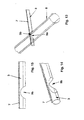
- FIGs. 16 and 17 is another possible connection variant between a Collection tube 8 and an absorber tube 3 not shown in detail.
- the above embodiments are based on a radiation absorber 1, the in turn has manifolds 8 (forward, return), in which in the manner of a parallel connection a plurality of absorber tubes 3 open at the end.
- the invention also detects radiation absorber 1, which in turn means of Known nipple elements, preferably by means of curved trained and end portions of adjacent absorber tubes 3 connecting nipple elements, are fluidically interconnected such that a meandering guided absorber tube 3 is formed. That is, a plurality of itself Axially parallel arranged absorber tubes 3 are in series one behind the other connected.
- At least the connecting sections 2a, 2b with an at least one-sided coating which is a protective lacquer or else a heat radiation can be particularly advantageously absorbing coating, are provided (not shown).
- the coating on the surface of the connecting portions 2a, 2b can thereby advantageously applied according to a PVD (physical vapor deposition) method, by the starting material for said coating on the physical Evaporation processes, for example by means of arc or electron beam, or the processes of sputtering in a high vacuum in a vapor phase be transferred and then on the surface of the connecting sections 2a, 2b re-precipitate.
- a PVD physical vapor deposition
Landscapes
- Engineering & Computer Science (AREA)
- Chemical & Material Sciences (AREA)
- Sustainable Energy (AREA)
- Life Sciences & Earth Sciences (AREA)
- Physics & Mathematics (AREA)
- Sustainable Development (AREA)
- Dispersion Chemistry (AREA)
- Thermal Sciences (AREA)
- Combustion & Propulsion (AREA)
- Mechanical Engineering (AREA)
- General Engineering & Computer Science (AREA)
- Particle Accelerators (AREA)
- Heat-Exchange Devices With Radiators And Conduit Assemblies (AREA)
Applications Claiming Priority (2)
| Application Number | Priority Date | Filing Date | Title |
|---|---|---|---|
| DE10356874 | 2003-12-03 | ||
| DE10356874 | 2003-12-03 |
Publications (1)
| Publication Number | Publication Date |
|---|---|
| EP1538403A2 true EP1538403A2 (fr) | 2005-06-08 |
Family
ID=34442462
Family Applications (1)
| Application Number | Title | Priority Date | Filing Date |
|---|---|---|---|
| EP04028281A Withdrawn EP1538403A2 (fr) | 2003-12-03 | 2004-11-30 | Absorbeur solaire en forme de plaque et son procédé de fabrication |
Country Status (2)
| Country | Link |
|---|---|
| EP (1) | EP1538403A2 (fr) |
| DE (1) | DE102004040813A1 (fr) |
Cited By (2)
| Publication number | Priority date | Publication date | Assignee | Title |
|---|---|---|---|---|
| EP2096376A3 (fr) * | 2008-02-07 | 2010-10-13 | Fundación Cidaut | Absorbeur métallique extrudé pour collecteur solaire |
| US20120186578A1 (en) * | 2010-12-30 | 2012-07-26 | Tvp Solar Sa | Vacuum solar thermal panel with pipe housing |
Families Citing this family (2)
| Publication number | Priority date | Publication date | Assignee | Title |
|---|---|---|---|---|
| DE102008026462A1 (de) * | 2008-06-03 | 2009-12-10 | Lappe, Wilhelm, Dr. | Verfahren und Vorrichtung zum kontinuierlichen Fügen |
| DE102015110487A1 (de) * | 2015-06-30 | 2016-07-07 | Viessmann Werke Gmbh & Co Kg | Solarkollektor |
-
2004
- 2004-08-24 DE DE102004040813A patent/DE102004040813A1/de not_active Withdrawn
- 2004-11-30 EP EP04028281A patent/EP1538403A2/fr not_active Withdrawn
Cited By (3)
| Publication number | Priority date | Publication date | Assignee | Title |
|---|---|---|---|---|
| EP2096376A3 (fr) * | 2008-02-07 | 2010-10-13 | Fundación Cidaut | Absorbeur métallique extrudé pour collecteur solaire |
| US20120186578A1 (en) * | 2010-12-30 | 2012-07-26 | Tvp Solar Sa | Vacuum solar thermal panel with pipe housing |
| US9404676B2 (en) * | 2010-12-30 | 2016-08-02 | Tvp Solar S.A. | Vacuum solar thermal panel with pipe housing |
Also Published As
| Publication number | Publication date |
|---|---|
| DE102004040813A1 (de) | 2005-07-07 |
Similar Documents
| Publication | Publication Date | Title |
|---|---|---|
| EP1281923B1 (fr) | Tube plat pour échangeur de chaleur et procédé de fabrication | |
| DE69115986T2 (de) | Rohr für Wärmetauscher und Verfahren zur Herstellung des Rohrs | |
| DE60209994T2 (de) | Wärmetauscherrohr | |
| EP0887235B1 (fr) | Elément de structure pour véhicules | |
| DE69210452T2 (de) | Wärmetauscher mit Rohrbündel, insbesondere für Kraftfahrzeug | |
| DE102015111648B4 (de) | Wärmeübertragerrohre mit Fluidverbindungskanälen | |
| DE69821372T2 (de) | Röhren für wärmetauscher und verfahren zu deren herstellung | |
| DE102006054814B4 (de) | Gelötetes Flachrohr für Kondensatoren und/oder Verdampfer | |
| DE19543149C2 (de) | Wärmetauscher, insbesondere Kältemittelverdampfer | |
| EP0566899B1 (fr) | Echangeur de chaleur, notamment évaporateur | |
| DE69600309T2 (de) | Flachrohr für einen wärmetauscher | |
| EP1468235B1 (fr) | Tube a plusieurs chambres soude | |
| DE2241407B2 (de) | Verfahren zur Herstellung eines Wärmetauscherelements | |
| EP0565813B1 (fr) | Echangeur de chaleur | |
| EP1139052B1 (fr) | Refroidisseur pour véhicules et procédé de fabrication | |
| EP1555503A2 (fr) | Tube plat d'échangeur de chaleur, en particulier pour condenseur | |
| DE10237769A1 (de) | Wärmeaustauscher und Verfahren zur Herstellung | |
| DE10014581C2 (de) | Stabilisierungsstrebe für ein Fahrwerk eines Fahrzeugs sowie Verfahren zur Herstellung derselben | |
| EP1296109B1 (fr) | Echangeur de chaleur avec un bloc de tubes plats ailettés et la méthode d'assemblage associée | |
| EP2167895B1 (fr) | Échangeur de chaleur | |
| EP1538403A2 (fr) | Absorbeur solaire en forme de plaque et son procédé de fabrication | |
| DE102006002932A1 (de) | Wärmetauscher und Herstellungsverfahren für Wärmetauscher | |
| DE10114078A1 (de) | Wärmetauscher und Herstellungsverfahren | |
| DE102007008536A1 (de) | Wärmetauscher | |
| DE19601276A1 (de) | Sammelkasten für einen Wärmeübertrager und ein Verfahren zur Herstellung |
Legal Events
| Date | Code | Title | Description |
|---|---|---|---|
| PUAI | Public reference made under article 153(3) epc to a published international application that has entered the european phase |
Free format text: ORIGINAL CODE: 0009012 |
|
| AK | Designated contracting states |
Kind code of ref document: A2 Designated state(s): AT BE BG CH CY CZ DE DK EE ES FI FR GB GR HU IE IS IT LI LU MC NL PL PT RO SE SI SK TR |
|
| AX | Request for extension of the european patent |
Extension state: AL HR LT LV MK YU |
|
| STAA | Information on the status of an ep patent application or granted ep patent |
Free format text: STATUS: THE APPLICATION IS DEEMED TO BE WITHDRAWN |
|
| 18D | Application deemed to be withdrawn |
Effective date: 20070601 |