EP1538015B1 - Closure system for fuel tank filler neck and method for opening said filler neck - Google Patents
Closure system for fuel tank filler neck and method for opening said filler neck Download PDFInfo
- Publication number
- EP1538015B1 EP1538015B1 EP05101678A EP05101678A EP1538015B1 EP 1538015 B1 EP1538015 B1 EP 1538015B1 EP 05101678 A EP05101678 A EP 05101678A EP 05101678 A EP05101678 A EP 05101678A EP 1538015 B1 EP1538015 B1 EP 1538015B1
- Authority
- EP
- European Patent Office
- Prior art keywords
- bezel
- shutter
- opening
- pipe head
- axis
- Prior art date
- Legal status (The legal status is an assumption and is not a legal conclusion. Google has not performed a legal analysis and makes no representation as to the accuracy of the status listed.)
- Expired - Lifetime
Links
- 239000000945 filler Substances 0.000 title claims abstract description 19
- 239000002828 fuel tank Substances 0.000 title claims abstract description 12
- 238000000034 method Methods 0.000 title claims description 6
- 230000000903 blocking effect Effects 0.000 claims description 8
- 230000000694 effects Effects 0.000 claims description 4
- 241000239290 Araneae Species 0.000 claims 3
- 230000002349 favourable effect Effects 0.000 claims 2
- 239000000446 fuel Substances 0.000 abstract description 18
- 230000008878 coupling Effects 0.000 abstract 1
- 238000010168 coupling process Methods 0.000 abstract 1
- 238000005859 coupling reaction Methods 0.000 abstract 1
- 239000004033 plastic Substances 0.000 description 9
- 229920003023 plastic Polymers 0.000 description 9
- 210000003739 neck Anatomy 0.000 description 8
- 229920001577 copolymer Polymers 0.000 description 6
- 239000000463 material Substances 0.000 description 6
- 229920001169 thermoplastic Polymers 0.000 description 6
- 239000007788 liquid Substances 0.000 description 5
- 229920000642 polymer Polymers 0.000 description 4
- 238000007789 sealing Methods 0.000 description 4
- 239000004416 thermosoftening plastic Substances 0.000 description 4
- 230000006835 compression Effects 0.000 description 3
- 238000007906 compression Methods 0.000 description 3
- 239000000203 mixture Substances 0.000 description 3
- 229920001400 block copolymer Polymers 0.000 description 2
- 239000007789 gas Substances 0.000 description 2
- 238000002844 melting Methods 0.000 description 2
- 230000008018 melting Effects 0.000 description 2
- 239000002184 metal Substances 0.000 description 2
- 230000000750 progressive effect Effects 0.000 description 2
- OKTJSMMVPCPJKN-UHFFFAOYSA-N Carbon Chemical compound [C] OKTJSMMVPCPJKN-UHFFFAOYSA-N 0.000 description 1
- 239000004952 Polyamide Substances 0.000 description 1
- 229910052799 carbon Inorganic materials 0.000 description 1
- 238000011109 contamination Methods 0.000 description 1
- 239000007799 cork Substances 0.000 description 1
- 238000000354 decomposition reaction Methods 0.000 description 1
- 230000006837 decompression Effects 0.000 description 1
- 230000007717 exclusion Effects 0.000 description 1
- 239000000835 fiber Substances 0.000 description 1
- 229920000578 graft copolymer Polymers 0.000 description 1
- 229920001519 homopolymer Polymers 0.000 description 1
- 238000003780 insertion Methods 0.000 description 1
- 230000037431 insertion Effects 0.000 description 1
- 238000009434 installation Methods 0.000 description 1
- 238000012423 maintenance Methods 0.000 description 1
- 239000007769 metal material Substances 0.000 description 1
- 229920002647 polyamide Polymers 0.000 description 1
- 229920000728 polyester Polymers 0.000 description 1
- 229920001470 polyketone Polymers 0.000 description 1
- 229920001291 polyvinyl halide Polymers 0.000 description 1
- 238000003825 pressing Methods 0.000 description 1
- 229920005604 random copolymer Polymers 0.000 description 1
- 150000003839 salts Chemical class 0.000 description 1
- 239000007787 solid Substances 0.000 description 1
- 229910001220 stainless steel Inorganic materials 0.000 description 1
- 239000010935 stainless steel Substances 0.000 description 1
- 239000000126 substance Substances 0.000 description 1
- 229920003002 synthetic resin Polymers 0.000 description 1
- 239000000057 synthetic resin Substances 0.000 description 1
- 229920002725 thermoplastic elastomer Polymers 0.000 description 1
Images


Classifications
-
- B—PERFORMING OPERATIONS; TRANSPORTING
- B60—VEHICLES IN GENERAL
- B60K—ARRANGEMENT OR MOUNTING OF PROPULSION UNITS OR OF TRANSMISSIONS IN VEHICLES; ARRANGEMENT OR MOUNTING OF PLURAL DIVERSE PRIME-MOVERS IN VEHICLES; AUXILIARY DRIVES FOR VEHICLES; INSTRUMENTATION OR DASHBOARDS FOR VEHICLES; ARRANGEMENTS IN CONNECTION WITH COOLING, AIR INTAKE, GAS EXHAUST OR FUEL SUPPLY OF PROPULSION UNITS IN VEHICLES
- B60K15/00—Arrangement in connection with fuel supply of combustion engines or other fuel consuming energy converters, e.g. fuel cells; Mounting or construction of fuel tanks
- B60K15/03—Fuel tanks
- B60K15/04—Tank inlets
- B60K15/0406—Filler caps for fuel tanks
-
- B—PERFORMING OPERATIONS; TRANSPORTING
- B60—VEHICLES IN GENERAL
- B60K—ARRANGEMENT OR MOUNTING OF PROPULSION UNITS OR OF TRANSMISSIONS IN VEHICLES; ARRANGEMENT OR MOUNTING OF PLURAL DIVERSE PRIME-MOVERS IN VEHICLES; AUXILIARY DRIVES FOR VEHICLES; INSTRUMENTATION OR DASHBOARDS FOR VEHICLES; ARRANGEMENTS IN CONNECTION WITH COOLING, AIR INTAKE, GAS EXHAUST OR FUEL SUPPLY OF PROPULSION UNITS IN VEHICLES
- B60K15/00—Arrangement in connection with fuel supply of combustion engines or other fuel consuming energy converters, e.g. fuel cells; Mounting or construction of fuel tanks
- B60K15/03—Fuel tanks
- B60K15/04—Tank inlets
- B60K15/05—Inlet covers
-
- B—PERFORMING OPERATIONS; TRANSPORTING
- B60—VEHICLES IN GENERAL
- B60K—ARRANGEMENT OR MOUNTING OF PROPULSION UNITS OR OF TRANSMISSIONS IN VEHICLES; ARRANGEMENT OR MOUNTING OF PLURAL DIVERSE PRIME-MOVERS IN VEHICLES; AUXILIARY DRIVES FOR VEHICLES; INSTRUMENTATION OR DASHBOARDS FOR VEHICLES; ARRANGEMENTS IN CONNECTION WITH COOLING, AIR INTAKE, GAS EXHAUST OR FUEL SUPPLY OF PROPULSION UNITS IN VEHICLES
- B60K15/00—Arrangement in connection with fuel supply of combustion engines or other fuel consuming energy converters, e.g. fuel cells; Mounting or construction of fuel tanks
- B60K15/03—Fuel tanks
- B60K15/04—Tank inlets
- B60K15/0406—Filler caps for fuel tanks
- B60K2015/0419—Self-sealing closure caps, e.g. that don't have to be removed manually
Abstract
Description
La présente invention concerne un système d'obturation pour tubulure de remplissage de réservoir à carburant.The present invention relates to a closure system for a fuel tank filling pipe.
Les tubulures de remplissage présentes sur les réservoirs à carburant, en particulier les réservoirs embarqués dans les véhicules automobiles, sont obturées pendant l'utilisation normale du réservoir, en dehors des périodes de remplissage. L'obturation est généralement réalisée au moyen d'un bouchon que l'on introduit dans la partie supérieure de la tubulure tout en lui imprimant un mouvement de rotation afin de fermer la tubulure de manière étanche aux liquides et aux gaz. Divers types de bouchons se rencontrent, en métal et/ou en matière plastique, l'étanchéité étant réalisée par serrage d'un joint obtenu par vissage ou par la rotation d'une clé introduite au centre de la partie extérieure à la tubulure.The filler necks on fuel tanks, in particular on-board tanks in motor vehicles, are plugged during normal use of the tank, outside the filling periods. The closure is generally achieved by means of a plug which is introduced into the upper part of the tubing while imparting a rotational movement to close the tubing in a liquid and gastight manner. Various types of plugs meet, metal and / or plastic, the seal being achieved by clamping a seal obtained by screwing or by the rotation of a key inserted in the center of the outside of the tubing.
Les opérations d'enlèvement du bouchon avant remplissage du réservoir et de replacement de ce bouchon et de fermeture de la tubulure après remplissage sont la plupart du temps effectuées manuellement par l'utilisateur ou le préposé d'une station-service délivrant du carburant. Lorsque le remplissage du réservoir se termine, un oubli de replacement du bouchon peut parfois se produire et donne lieu alors à la perte de ce dernier et au maintien de la tubulure ouverte à l'atmosphère pendant un temps plus ou moins long. Durant cette période, des pertes en carburant liquide peuvent survenir et des vapeurs s'échappent dans l'atmosphère ambiante.The operations of removing the cap before filling the tank and replacing this cap and closing the tubing after filling are most often done manually by the user or the attendant of a service station delivering fuel. When the filling of the tank ends, an omission of replacement of the plug can sometimes occur and then gives rise to the loss of the latter and the maintenance of the tubing open to the atmosphere for a longer or shorter time. During this period, liquid fuel losses may occur and vapors escape into the ambient atmosphere.
Dans le but d'éviter les pertes de bouchon et la contamination de l'atmosphère qui s'ensuit, des systèmes d'obturation intégrés à la tubulure de remplissage ont été proposés, en remplacement du bouchon traditionnel. On connaît par exemple un système pour robot de remplissage avec toutes les caractéristiques du préambule de la revendication 1 et de la revendication 8 décrit dans le
Dans ce système, il est cependant difficile d'aligner parfaitement le bec du pistolet de distribution dans l'axe de la bague et la rotation du bec du pistolet ne peut être envisagée facilement dans le cas d'une utilisation manuelle ne faisant pas appel à un robot, par exemple avec un pistolet traditionnel qui équipe les stations-service actuelles. Avec ce système, au contraire, le réservoir ne peut être rempli que dans une installation de distribution de carburant entièrement robotisée.In this system, however, it is difficult to perfectly align the nozzle of the dispensing gun in the axis of the ring and the rotation of the nozzle of the gun can be considered easily in the case of manual use not making not using a robot, for example with a traditional pistol that equips the current service stations. With this system, on the contrary, the tank can only be filled in a fully robotic fuel distribution system.
L'invention a dès lors pour objet un système d'obturation qui permette la suppression du bouchon de tubulure et la fermeture automatique de cette dernière après remplissage et ne requière pas nécessairement d'installation robotisée de distribution de carburant tout en autorisant par contre l'utilisation manuelle de pistolets de distribution traditionnels équipant les stations-service existantes.The invention therefore relates to a closure system that allows the removal of the tubing plug and the automatic closure of the latter after filling and does not necessarily require a robotic fuel dispensing installation while allowing the cons against manual use of traditional dispensing guns at existing service stations.
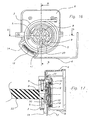
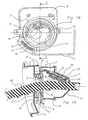
A cet effet l'invention concerne un système d'obturation intégré à une tête de tubulure de remplissage de réservoir à carburant, comprenant un obturateur et permettant l'ouverture automatique de la tubulure via l'action d'un pistolet distributeur de carburant, selon lequel l'obturateur est escamotable sous l'action d'une poussée dirigée contre lui selon un axe parallèle à l'axe de la tête de tubulure et en ce qu'un ressort de rappel permet de maintenir l'obturateur en position fermée.To this end, the invention relates to a closure system integrated into a fuel tank filling pipe head, comprising a shutter and allowing the opening of the pipe automatically via the action of a fuel dispensing gun, according to which shutter is retractable under the action of a thrust directed against it along an axis parallel to the axis of the tubing head and in that a return spring keeps the shutter in the closed position.
Par réservoir à carburant, on entend désigner tout type de réservoir capable de stocker un carburant liquide et/ou gazeux dans des conditions de pression et température variées. Plus particulièrement visés sont les réservoirs du type de ceux que l'on rencontre dans les véhicules automobiles. Dans le vocable "véhicule automobile", on entend inclure aussi bien les voitures, les motocyclettes et les camions.By fuel tank is meant any type of tank capable of storing a liquid fuel and / or gas under varying pressure and temperature conditions. More particularly referred to are the tanks of the type found in motor vehicles. In the term "motor vehicle" is meant to include cars, motorcycles and trucks.
La tubulure de remplissage est un conduit qui communique avec l'intérieur du réservoir et qui permet l'introduction de carburant.The filler neck is a conduit that communicates with the interior of the tank and allows the introduction of fuel.
Le réservoir et la tubulure peuvent être réalisés en métal ou en matière plastique.The tank and the tubing can be made of metal or plastic.
Le système d'obturation conforme à l'invention est bien adapté à un ensemble réservoir et tubulure de remplissage dont au moins un des deux composants de l'ensemble est réalisé en matière plastique. Il est particulièrement bien adapté à un ensemble dont la tubulure de remplissage est réalisée en matière plastique. Le système d'obturation conforme à l'invention comprend lui-même au moins une pièce en matière plastique.The closure system according to the invention is well suited to a reservoir and filling pipe assembly, at least one of the two components of the assembly is made of plastic material. It is particularly well suited to an assembly whose filler pipe is made of plastic. The closure system according to the invention itself comprises at least one plastic part.
Par matière plastique, on entend désigner toute matière comprenant au moins un polymère en résine de synthèse.By plastic material is meant any material comprising at least one synthetic resin polymer.
Tous les types de matière plastique peuvent convenir. Des matières plastiques convenant bien appartiennent à la catégorie des matières thermoplastiques.All types of plastics may be suitable. Well-suited plastics belong to the thermoplastics category.
Par matière thermoplastique, on désigne tout polymère thermoplastique, y compris les élastomères thermoplastiques, ainsi que leurs mélanges. On désigne par le terme "polymère" aussi bien les homopolymères que les copolymères (binaires ou ternaires notamment). Des exemples de tels copolymères sont, de manière non limitative : les copolymères à distribution aléatoire, les copolymères séquencés, les copolymères à blocs et les copolymères greffés.Thermoplastic means any thermoplastic polymer, including thermoplastic elastomers, and mixtures thereof. The term "polymer" denotes both homopolymers and copolymers (especially binary or ternary). Examples of such copolymers are, but are not limited to: random copolymers, block copolymers, block copolymers and graft copolymers.
Tout type de polymère ou de copolymère thermoplastique dont la température de fusion est inférieure à la température de décomposition conviennent. Les matières thermoplastiques de synthèse qui présentent une plage de fusion étalée sur au moins 10 degrés Celsius conviennent particulièrement bien. Comme exemple de telles matières, on trouve celles qui présentent une polydispersion de leur masse moléculaire.Any type of thermoplastic polymer or copolymer whose melting point is below the decomposition temperature is suitable. Synthetic thermoplastics having a melting range spread over at least 10 degrees Celsius are particularly suitable. Examples of such materials are those having a polydispersion of their molecular weight.
En particulier, on peut utiliser des polyoléfmes, des polyhalogénures de vinyle, des polyesters thermoplastiques, des polycétones, des polyamides et leurs copolymères. Un mélange de polymères ou de copolymères peut aussi être utilisé, de même qu'un mélange de matières polymériques avec des charges inorganiques, organiques et/ou naturelles comme, par exemple, mais non limitativement : le carbone, les sels et autres dérivés inorganiques, les fibres naturelles ou polymériques. Il est également possible d'utiliser des structures multicouches constituées de couches empilées et solidaires comprenant au moins un des polymères ou copolymères décrits supra.In particular, it is possible to use polyolefms, polyvinyl halides, thermoplastic polyesters, polyketones, polyamides and their copolymers. A mixture of polymers or copolymers may also be used, as well as a mixture of polymeric materials with inorganic, organic and / or natural fillers such as, for example, but not limited to: carbon, salts and other inorganic derivatives, natural or polymeric fibers. It is also possible to use multilayer structures consisting of stacked and solid layers comprising at least one of the polymers or copolymers described above .
Le système d'obturation selon l'invention a pour but de jouer le rôle d'un bouchon qui ferme de manière étanche la partie supérieure de la tubulure de remplissage en dehors des périodes de remplissage du réservoir dans le but d'éviter tout dégagement et perte de carburant liquide et vapeur vers l'atmosphère lorsque le réservoir contient du carburant.The sealing system according to the invention is intended to act as a stopper sealing the upper part of the filler neck outside the filling periods of the reservoir in order to avoid any disengagement and loss of liquid fuel and vapor to the atmosphere when the tank contains fuel.
Selon l'invention, le système d'obturation est intégré à la tête de tubulure, c'est-à-dire qu'il est incorporé à un ensemble de pièces qui sont montées sur l'extrémité supérieure de la tubulure de remplissage et qui forment une tête dont une partie constituée par un corps coiffe la tubulure et une autre partie est insérée dans le haut de cette tubulure sur une longueur déterminée.According to the invention, the closure system is integrated with the tubing head, that is to say it is incorporated in a set of parts which are mounted on the upper end of the filler neck and which form a head part of which consists of a body cap the tubing and another part is inserted into the top of this tubing for a predetermined length.
Le système d'obturation permet l'ouverture automatique de la tubulure via l'action d'un pistolet distributeur de carburant. Par ouverture automatique, on entend ouverture réalisée sous la seule action du pistolet distributeur, à l'exclusion de toute autre sollicitation mécanique. Le pistolet distributeur est celui qui équipe les tuyaux souples des pompes à carburant dans les stations-service.The shutter system allows the automatic opening of the tubing via the action of a fuel dispensing gun. By automatic opening, we means opening made under the sole action of the dispensing gun, to the exclusion of any other mechanical stress. The dispensing gun is the one that equips the flexible hoses of the fuel pumps at the service stations.
Le système d'obturation conforme à l'invention comprend un obturateur, c'est-à-dire un dispositif fermant le passage des gaz et des liquides dans la tubulure. Cet obturateur peut se trouver sous différentes formes dans le système d'obturation selon l'invention. Une forme qui convient bien est une forme de plaque mobile qui bouche le passage lorsqu'elle se trouve en position fermée.The shutter system according to the invention comprises a shutter, that is to say a device closing the passage of gases and liquids in the tubing. This shutter can be in different forms in the shutter system according to the invention. A form that is suitable is a form of movable plate that blocks the passage when in the closed position.
L'obturateur est escamotable sous l'action d'une poussée dirigée contre lui selon un axe parallèle à l'axe de la tête de tubulure. Divers moyens peuvent être présents pour rendre l'obturateur escamotable. Un moyen ayant donné de bons résultats est une tige solidaire de la tête de tubulure et située à la périphérie de l'obturateur, qui peut servir d'axe de rotation permettant le basculement de l'obturateur.The shutter is retractable under the action of a thrust directed against it along an axis parallel to the axis of the tubing head. Various means may be present to make the shutter retractable. One means that has given good results is a rod secured to the tubing head and located at the periphery of the shutter, which can serve as a rotational axis for the tilting of the shutter.
L'obturateur est maintenu en position fermée par un ressort de rappel. Un ressort convenant bien est un ressort de torsion disposé autour de la tige et dont une extrémité est solidaire de l'obturateur.The shutter is held in the closed position by a return spring. A suitable spring is a torsion spring disposed around the rod and one end of which is integral with the shutter.
L'obturateur est muni de moyens de blocage qui sont débrayables par un effort de poussée parallèle à l'axe de la tête de tubulure.The shutter is provided with locking means which are disengageable by a thrust force parallel to the axis of the tubing head.
Par moyens de blocage, on entend des moyens qui empêchent l'escamotage de l'obturateur.Blocking means means that prevent the retraction of the shutter.
Des moyens de blocage appropriés peuvent être utilisés. Des moyens de blocage possibles qui donnent de bons résultats sont constitués d'une palette capable de verrouiller la rotation d'un anneau qui peut être engagé à serrage avec l'obturateur.Suitable blocking means may be used. Possible blocking means which give good results consist of a pallet capable of locking the rotation of a ring which can be engaged in clamping with the shutter.
Selon l'invention de tels moyens de blocage sont constitués d'une lunette tronc-cylindrique en forme d'anneau pouvant tourner autour de son axe et aplati sur ses deux faces inférieure et supérieure, cette lunette pouvant être engagée à serrage avec l'obturateur. Cette lunette est réalisée en matériau de bonne stabilité dimensionnelle et de bonne résistance chimique en présence de carburant. Les matériaux plastiques ou métalliques conviennent bien. L'acier inoxydable a donné de bons résultats.According to the invention, such locking means consist of a ring-shaped truncated-cylindrical bezel rotatable about its axis and flattened on its two lower and upper faces, this telescope being engageable with the shutter . This bezel is made of material of good dimensional stability and good chemical resistance in the presence of fuel. Plastic or metallic materials are suitable. Stainless steel has given good results.
Le verrouillage de la lunette par la palette peut être réalisé par tout dispositif approprié. Un exemple d'un tel dispositif est une palette, en forme de cercle ou de tronc de cône ajouré, qui porte sur sa circonférence un ergot qui peut être inséré dans une encoche située sur la lunette. Dans cet exemple, la palette peut être déformée par un effort appliqué perpendiculairement à sa surface, de telle manière que l'ergot soit désengagé de l'encoche de la lunette.The locking of the bezel by the pallet can be achieved by any suitable device. An example of such a device is a pallet, shaped like circle or openwork truncated cone, which carries on its circumference a lug that can be inserted into a notch on the bezel. In this example, the pallet may be deformed by a force applied perpendicular to its surface, so that the lug is disengaged from the notch of the bezel.
Un autre exemple qui a donné d'excellents résultats est celui où la palette communique la poussée à un ressort de compression en forme d'épingle recourbée qui se termine par un ergot pouvant être inséré dans une encoche située sur la lunette et sur un corps supportant cette lunette. Dans cet autre exemple, la déformation de la palette est capable de comprimer le ressort en forme d'épingle et de désengager l'ergot de l'encoche de la lunette.Another example which has given excellent results is that in which the pallet communicates the thrust to a curved pin-shaped compression spring which terminates in a pin that can be inserted into a notch located on the bezel and on a supporting body. this bezel. In this other example, the deformation of the pallet is capable of compressing the pin-shaped spring and disengaging the lug of the notch of the bezel.
Lorsque les moyens de blocage sont constitués d'une palette comme décrit supra, l'engagement à serrage de la lunette avec l'obturateur peut être réalisé au moyen d'un dispositif à baïonnette dont les parties qui coopèrent sont disposées, respectivement, sur la surface cylindrique intérieure de la lunette et sur le pourtour de l'obturateur.When the blocking means consist of a pallet as described above, the clamp engagement of the bezel with the shutter can be achieved by means of a bayonet device whose cooperating parts are arranged, respectively, on the inner cylindrical surface of the bezel and around the shutter.
Dans cette configuration des moyens de blocage de l'obturateur du système selon l'invention, les parties du dispositif à baïonnette peuvent être constituées d'ergots aplatis dont l'épaisseur varie en forme de biseau et qui sont disposés renversés l'un au-dessus de l'autre.In this configuration of the blocking means of the shutter of the system according to the invention, the parts of the bayonet device may consist of flattened lugs whose thickness varies in the form of a bevel and which are arranged reversed one above the other. above each other.
Un deuxième ressort de torsion permet de maintenir la lunette en position déverrouillée et desserrée lorsque l'obturateur est ouvert. Ce ressort possède une de ses extrémités fixée au corps coiffant l'extrémité supérieure de la tubulure de remplissage. L'autre extrémité du deuxième ressort est solidaire de la lunette. Un moyen de solidarisation est, par exemple, l'introduction d'une extrémité recourbée d'une spire du ressort dans un orifice percé dans une languette qui prolonge la lunette, l'extrémité du ressort pouvant pivoter librement dans l'orifice.A second torsion spring holds the bezel in the unlocked and released position when the shutter is open. This spring has one of its ends fixed to the body covering the upper end of the filler neck. The other end of the second spring is secured to the bezel. A securing means is, for example, the introduction of a curved end of a coil of the spring in a hole drilled in a tongue which extends the bezel, the end of the spring being able to pivot freely in the orifice.
Dans cette configuration du système selon l'invention, lorsque le réservoir est monté sur un véhicule automobile, une tringle peut aussi relier la lunette à un portillon de carrosserie protégeant la tête de tubulure de remplissage et permettre la tension du deuxième ressort de torsion et la rotation de la lunette jusqu'à une position verrouillée lorsque le portillon est fermé.In this configuration of the system according to the invention, when the tank is mounted on a motor vehicle, a rod can also connect the bezel to a body door protecting the filler neck head and allow the tension of the second torsion spring and the rotation of the telescope to a locked position when the gate is closed.
Le verrouillage en rotation de la lunette peut être réalisé de la manière décrite supra, par exemple au moyen de la décompression d'un ressort en épingle recourbée terminée par un ergot qui est inséré dans une encoche située sur la lunette.The rotation lock of the telescope can be achieved in the manner described above , for example by means of the decompression of a bent pin spring terminated by a lug which is inserted into a notch on the bezel.
Un mode de fixation de la tringle à la lunette est celui dans lequel la tringle constitue le coulisseau d'une fente dans une pièce oblongue en forme de coulisse portée par une languette solidaire de la lunette. Avantageusement, la coulisse est dimensionnée de manière telle que l'ouverture du portillon à partir d'une position fermée soit sans effet sur l'état verrouillé en rotation de la lunette.One way of fixing the rod to the telescope is that in which the rod constitutes the slide of a slot in an oblong piece in the form of a slide carried by a tab integral with the telescope. Advantageously, the slide is dimensioned such that the opening of the gate from a closed position has no effect on the locked state in rotation of the bezel.
L'invention concerne aussi un procédé pour ouvrir une tête de tubulure de remplissage d'un réservoir à carburant par l'introduction d'un pistolet distributeur de carburant, selon lequel, après l'ouverture d'un portillon de carrosserie protégeant la tête de tubulure de remplissage, l'introduction à force du pistolet selon une direction parallèle à l'axe de la tête de tubulure contre une palette provoque d'abord le déverrouillage d'une lunette en forme d'anneau aplati mobile en rotation, ensuite le déblocage et le desserrage d'un obturateur suivi de son basculement et de son ouverture par escamotage, la force de poussée d'introduction étant suffisante pour vaincre une force de rappel exercée par un ressort et le déverrouillage de la rotation de la lunette et l'ouverture de l'obturateur s'effectuant de la manière suivante :
- a) une force de poussée est exercée sur la palette selon une direction parallèle à l'axe de la tête de tubulure, ce qui provoque d'abord le déblocage de la rotation de la lunette et ensuite l'ouverture progressive d'une baïonnette tendant à débloquer et desserrer l'obturateur;
- b) un deuxième ressort tendu en torsion, dont une extrémité est fixe et l'autre est solidaire de la lunette se détend en entraînant la lunette en rotation dans un sens propice à l'ouverture de la baïonnette;
- c) sous l'effet de cette rotation, des ergots taillés en biseau et disposés sur la face cylindrique interne de la lunette se désengagent de biseaux analogues renversés situés autour de l'obturateur, de manière à désolidariser la lunette et l'obturateur précédemment assemblés à force par serrage;
- d) un joint circulaire compressible disposé à la périphérie de l'obturateur, entre ce dernier et la lunette se décomprime et l'obturateur bascule.
- a) a pushing force is exerted on the pallet in a direction parallel to the axis of the tubular head, which first causes the unlocking of the rotation of the telescope and then the progressive opening of a bayonet tending to unlock and loosen the shutter;
- b) a second spring tensioned in torsion, one end is fixed and the other is secured to the telescope relaxes by driving the rotating bezel in a direction conducive to the opening of the bayonet;
- c) under the effect of this rotation, beveled pins and arranged on the inner cylindrical face of the bezel disengage inverted analog bevels located around the shutter, so as to separate the previously assembled bezel and shutter by force by tightening;
- d) a compressible seal disposed on the periphery of the shutter, between the latter and the bezel decompresses and the shutter tilts.
Dans ce procédé, la signification des termes employés est identique à celle des mêmes termes utilisés dans la description du système d'obturation qui précède.In this process, the meaning of the terms used is identical to that of the same terms used in the description of the preceding sealing system.
Selon ce procédé, après ouverture, la tête de tubulure de remplissage est obturée à nouveau et verrouillée via la fermeture du portillon de carrosserie, par un mouvement latéral d'une tringle dont une extrémité est articulée en un point situé à la base du portillon et l'autre fait office de coulisseau d'une fente dans une pièce oblongue en forme de coulisse portée par une languette qui prolonge la lunette, le mouvement de la tringle faisant tourner la lunette dans un sens propice à la fermeture de la baïonnette, au serrage du joint et au blocage de la lunette en rotation par la palette.According to this method, after opening, the filler neck head is closed again and locked via the closure of the body door, by a lateral movement of a rod whose end is hinged at a point located at the base of the gate and the other acts as slider of a slot in an oblong piece in the form of a slide carried by a tongue which extends the telescope, the movement of the rod rotating the bezel in a direction conducive to the closing the bayonet, tightening the seal and locking the rotating bezel by the pallet.
Comme exposé plus haut pour le système d'obturation selon l'invention, le verrouillage en rotation de la lunette peut se réaliser, par exemple, en décomprimant un ressort en épingle recourbée terminée par un ergot qui vient s'insérer dans une encoche qui a été creusée sur la lunette.As explained above for the closure system according to the invention, the locking in rotation of the telescope can be achieved, for example, by decompressing a bent pin spring terminated by a lug which is inserted into a notch which has been dug on the telescope.
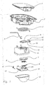
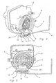
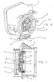
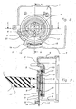
Les figures qui suivent ont pour but d'illustrer l'invention dans le cas particulier de l'obturation d'une tubulure de remplissage de réservoir à carburant d'un véhicule automobile, sans en limiter sa portée.The following figures are intended to illustrate the invention in the particular case of the closure of a fuel tank filling pipe of a motor vehicle, without limiting its scope.
La
Les
Les
Les
Les
Les
Les
A la
A la
A la
Aux
A la
Aux
Aux
A la
Claims (9)
- Closure system integrated with a fuel tank filler pipe head, comprising a shutter (10) and enabling the automatic opening of the pipe via the action of a fuel-dispensing nozzle (22), according to which the shutter (10) is retractable under the action of a thrust directed against it along an axis parallel to the axis of the pipe head, a return spring (11) enables the shutter (10) to be kept in the closed position, and the shutter (10) is fitted with blocking means that can be released by a thrust force parallel to the axis of the pipe head, characterized in that the blocking means consist of a truncated-cylinder bezel (5) engaged, with clamping, with the shutter (10), which can turn about its axis and is flattened on both its lower and upper faces.
- System according to the preceding claim, characterized in that it comprises a compressible circular seal (7) arranged at the periphery of the shutter (10), between the latter and the bezel (5).
- System according to the preceding claim, characterized in that the clamping engagement is produced by means of a bayonet device whose interacting parts (23) (24) are arranged, respectively, on the inner cylindrical surface of the bezel and on the periphery of the shutter.
- System according to the preceding claim, characterized in that the parts of the bayonet device consist of flattened lugs (23) (24) whose thickness varies in the form of a bevel and which are arranged inverted one on top of the other.
- System according to any one of Claims 2 to 4, characterized in that a torsion spring (3) enables the bezel (5) to be kept in the unlocked and unclamped position when the shutter (10) is open.
- System according to any one of Claims 2 to 5, characterized in that a rod (4)is capable of connecting the bezel (5) to a bodywork flap (1) protecting the filler pipe head and enables the torsion spring (3) to be tensioned and the bezel (5) to be rotated as far as a locked position when the flap (1) is closed.
- System according to the preceding claim, characterized in that the rod (4) is fastened to the bezel (5), at the same constituting the slider of a slot (15) in an oblong piece (14) in the form of a slideway borne by a tongue (17) integral with the bezel (5), the slideway (15) being dimensioned in such a way that the opening of the flap (1) from a closed position has no effect on the locked-in-rotation state of the bezel (5).
- Method for opening a fuel tank filler pipe head by the introduction of a fuel-dispensing nozzle (22), characterized in that, after opening a bodywork flap (1) protecting the filler pipe head, the forceful introduction of the nozzle (22) in a direction parallel to the axis of the pipe head against a spider (8) causes first of all the unlocking of a bezel (5) in the form of a rotationally mobile flattened ring, then the unblocking and unclamping of a shutter (10) followed by its tilting and its opening by retraction, the introduction thrust force being sufficient to overcome a return force exerted by a spring (11), and the unlocking of the rotation of the bezel (5) and the opening of the shutter (10) being carried out in the following way:a) a thrust force is exerted on the spider (8) in a direction parallel to the axis of the pipe head, which causes first of all the unblocking of the rotation of the bezel (5) and then the gradual opening of a bayonet tending to unblock and unclamp the shutter (10);b) a second spring (3), tensioned in torsion and one end of which is fixed and the other end of which is integral with the bezel (5), relaxes and so drives the bezel (5) in rotation in a direction favourable to the opening of the bayonet;c) under the effect of this rotation, bevel-cut lugs (23) arranged on the internal cylindrical face of the bezel (5) disengage from analogous inverted bevels (24) situated around the shutter (10), so as to disunite the bezel (5) and the shutter (10) previously assembled with force by clamping;d) a compressible circular seal (7) arranged at the periphery of the shutter (10), between the latter and the bezel (5), decompresses and the shutter (10) tilts.
- Method according to the preceding claim, characterized in that, after opening, the filler pipe head is closed off again and locked via the closing of the bodywork flap (1), by a lateral movement of a rod (4), one end of which is articulated at a point (18) situated at the base of the flap and the other end of which serves as a slider of a slot (15) in an oblong piece (14) in the form of a slideway borne by a tongue (17) that extends the bezel (5), the movement of the rod (4) causing the bezel (5) to turn in a direction favourable to closing the bayonet, to clamping the seal (7) and to the blocking of the rotation of the bezel (5) by the spider (8).
Applications Claiming Priority (3)
| Application Number | Priority Date | Filing Date | Title |
|---|---|---|---|
| FR0110044 | 2001-07-25 | ||
| FR0110044A FR2827818B1 (en) | 2001-07-25 | 2001-07-25 | BLINDING SYSTEM FOR FUEL TANK FILLING TUBE AND METHOD FOR OPENING SAME |
| EP02772105A EP1414664B1 (en) | 2001-07-25 | 2002-07-24 | Closure system for fuel tank filler neck and method for opening said filler neck |
Related Parent Applications (2)
| Application Number | Title | Priority Date | Filing Date |
|---|---|---|---|
| EP02772105A Division EP1414664B1 (en) | 2001-07-25 | 2002-07-24 | Closure system for fuel tank filler neck and method for opening said filler neck |
| EP02772105.9 Division | 2002-07-24 |
Publications (3)
| Publication Number | Publication Date |
|---|---|
| EP1538015A2 EP1538015A2 (en) | 2005-06-08 |
| EP1538015A3 EP1538015A3 (en) | 2010-07-14 |
| EP1538015B1 true EP1538015B1 (en) | 2011-09-28 |
Family
ID=8865971
Family Applications (2)
| Application Number | Title | Priority Date | Filing Date |
|---|---|---|---|
| EP02772105A Expired - Lifetime EP1414664B1 (en) | 2001-07-25 | 2002-07-24 | Closure system for fuel tank filler neck and method for opening said filler neck |
| EP05101678A Expired - Lifetime EP1538015B1 (en) | 2001-07-25 | 2002-07-24 | Closure system for fuel tank filler neck and method for opening said filler neck |
Family Applications Before (1)
| Application Number | Title | Priority Date | Filing Date |
|---|---|---|---|
| EP02772105A Expired - Lifetime EP1414664B1 (en) | 2001-07-25 | 2002-07-24 | Closure system for fuel tank filler neck and method for opening said filler neck |
Country Status (10)
| Country | Link |
|---|---|
| US (1) | US7063113B2 (en) |
| EP (2) | EP1414664B1 (en) |
| JP (1) | JP4141383B2 (en) |
| KR (1) | KR100919438B1 (en) |
| CN (2) | CN100396508C (en) |
| AT (2) | ATE295790T1 (en) |
| BR (1) | BR0211412A (en) |
| DE (1) | DE60204226D1 (en) |
| FR (1) | FR2827818B1 (en) |
| WO (1) | WO2003010022A1 (en) |
Families Citing this family (44)
| Publication number | Priority date | Publication date | Assignee | Title |
|---|---|---|---|---|
| GB0312184D0 (en) | 2003-05-28 | 2003-07-02 | Feeney Aiden | Delivery flow valve |
| DE10336776B4 (en) | 2003-08-08 | 2010-04-08 | Alfmeier Präzision Aktiengesellschaft Baugruppen und Systemlösungen | Filler neck for the fuel tank of a motor vehicle with an automatic tank closure |
| US20070103787A1 (en) * | 2003-09-12 | 2007-05-10 | Inergy Automotive Systems Research | Closure for fuel-tank filler pipe |
| FR2861655B1 (en) * | 2003-10-31 | 2006-01-06 | Inergy Automotive Systems Res | DEVICE FOR FILLING A FILLING TUBE FROM A LIQUID TANK, TANK EQUIPPED WITH SUCH A DEVICE AND MOTOR VEHICLE COMPRISING SUCH A TANK |
| WO2005067368A2 (en) | 2003-11-21 | 2005-07-28 | Nps Allelix Corp. | Production of glucagon like peptide 2 and analogs |
| DE102004002994B3 (en) * | 2004-01-19 | 2005-09-22 | Itw Automotive Products Gmbh & Co. Kg | Filler neck for filling fuel into a vehicle tank |
| US6880594B1 (en) * | 2004-03-19 | 2005-04-19 | Eaton Corporation | Method and arrangement for sealing a capless fuel tank filler tube |
| JP4490763B2 (en) * | 2004-08-23 | 2010-06-30 | 本田技研工業株式会社 | Vehicle fuel cap |
| JP4504772B2 (en) * | 2004-09-27 | 2010-07-14 | 株式会社ニフコ | Fuel tank refueling pipe |
| FR2879521B1 (en) * | 2004-12-16 | 2007-03-09 | Inergy Automotive Systems Res | SHUTTERING SYSTEM FOR FUEL TANK FILLING TUBE |
| FR2879522B1 (en) * | 2004-12-16 | 2008-05-30 | Inergy Automotive Systems Res | LOCKING SYSTEM FOR A SHUTTER INTEGRATED WITH A FUEL TANK FILLING TUBE HEAD |
| US7165583B1 (en) * | 2005-01-31 | 2007-01-23 | Eaton Corporation | Door latch for capless filler neck |
| FR2881688B1 (en) * | 2005-02-04 | 2008-09-05 | Inergy Automotive Systems Res | SHUTTERING SYSTEM FOR FUEL TANK FILLING TUBE |
| ATE409139T1 (en) * | 2005-02-10 | 2008-10-15 | Gerdes Gmbh | LID-LESS LOCKABLE SOCKET CLOSURE FOR A FILLER NECK OF A TANK OF A MOTOR VEHICLE |
| US7007726B1 (en) * | 2005-04-18 | 2006-03-07 | Eaton Corporation | Cover closure assembly and method for fuel tank filler |
| FR2886367B1 (en) * | 2005-05-24 | 2008-12-26 | Inergy Automotive Systems Res | VALVE FOR AIR FLOW CIRCUIT OF A LIQUID TANK |
| JP4692360B2 (en) * | 2005-12-02 | 2011-06-01 | 豊田合成株式会社 | Tank opening and closing device |
| US20070267067A1 (en) * | 2006-05-16 | 2007-11-22 | Water Square Sports Co., Ltd. | Valve for a snorkel |
| FR2901191B1 (en) * | 2006-05-22 | 2008-12-26 | Inergy Automotive Systems Res | SHUTTERING SYSTEM FOR FUEL TANK FILLING TUBE |
| DE102006031463A1 (en) * | 2006-07-07 | 2008-01-10 | Itw Automotive Products Gmbh & Co. Kg | Filler neck for filling diesel fuel into a vehicle tank |
| WO2008013325A1 (en) * | 2006-07-28 | 2008-01-31 | Toyoda Gosei Co., Ltd. | Opening/closing device for tank |
| FR2904268B1 (en) * | 2006-07-31 | 2009-04-24 | Inergy Automotive Systems Res | FILLING SYSTEM OF A TANK |
| JP4838664B2 (en) * | 2006-08-11 | 2011-12-14 | 株式会社アステア | Filling port closing device |
| GB2443427B (en) * | 2006-11-03 | 2011-03-30 | Fuel Savers Ltd | Valve |
| US20080230147A1 (en) * | 2007-01-22 | 2008-09-25 | Inergy Auto. Systems Research (Societe Anaonyme) | Sealing system for fill pipe head |
| AT9945U1 (en) * | 2007-03-27 | 2008-06-15 | Magna Steyr Fuel Systems Gesmb | FILLING IN A FUEL TANK WITH PROTECTION BEFORE FAILING |
| KR100786535B1 (en) * | 2007-05-07 | 2007-12-17 | 정호순 | Filler tube assembly |
| FR2917340A1 (en) * | 2007-06-13 | 2008-12-19 | Inergy Automotive Systems Res | SHUTTERING SYSTEM FOR FILLING TUBE HEAD AND ASSOCIATED TUBE. |
| FR2917341A1 (en) * | 2007-06-14 | 2008-12-19 | Inergy Automotive Systems Res | FILLING SYSTEM FOR FILLING TUBE HEAD AND ASSOCIATED TUBE |
| JP2009001231A (en) * | 2007-06-25 | 2009-01-08 | Nifco Inc | Opening/closing device for oil-feeding port |
| JP4379518B2 (en) * | 2007-11-29 | 2009-12-09 | トヨタ自動車株式会社 | Fuel tank fueling part structure |
| JP4924445B2 (en) * | 2008-01-24 | 2012-04-25 | 豊田合成株式会社 | Tank opening and closing device |
| WO2009137812A2 (en) * | 2008-05-08 | 2009-11-12 | Amtrol Licensing Inc. | Support stand for pressure vessel |
| DE102008039311B4 (en) * | 2008-08-22 | 2013-02-21 | Itw Automotive Products Gmbh & Co. Kg | Filler neck for filling fuel into a vehicle tank |
| JP5097221B2 (en) * | 2010-01-19 | 2012-12-12 | 八千代工業株式会社 | Plastic fuel tank component fixing structure |
| WO2012114484A1 (en) * | 2011-02-23 | 2012-08-30 | トヨタ自動車株式会社 | Gas-supplying unit structure for fuel tank |
| DE102011117459A1 (en) * | 2011-06-29 | 2013-01-03 | Volkswagen Aktiengesellschaft | Filler neck for a fuel tank |
| BR112014020227A8 (en) * | 2012-02-20 | 2017-07-11 | Honda Motor Co Ltd | STRUCTURE FOR FUEL SUPPLY TUBE SUPPLY SECTION |
| CN103335767B (en) * | 2013-06-13 | 2015-12-16 | 东风亚普汽车部件有限公司 | Car fuel tank cap torque test device |
| JP6203106B2 (en) * | 2014-04-11 | 2017-09-27 | 株式会社ニフコ | Oil filler opening and closing device |
| US9873322B2 (en) * | 2015-09-16 | 2018-01-23 | Stant Usa Corp. | Closure assembly for fuel tank filler neck |
| CN105922864A (en) * | 2016-05-20 | 2016-09-07 | 斯丹德汽车系统(苏州)有限公司 | Non-cap type fuel tank cap |
| CN114269588A (en) * | 2019-05-14 | 2022-04-01 | 伊利诺斯工具制品有限公司 | Articulated vehicle energy door |
| CN111169278A (en) * | 2019-09-18 | 2020-05-19 | 宁波海曙广运机电工程有限公司 | Automatic opening and closing device of convenient oil tank cover |
Family Cites Families (7)
| Publication number | Priority date | Publication date | Assignee | Title |
|---|---|---|---|---|
| US2145758A (en) * | 1937-02-09 | 1939-01-31 | Roy S Fellows | Tank closure |
| US5145081A (en) * | 1990-10-03 | 1992-09-08 | Trilby, Ltd. | Capless closure for a fuel tank filler pipe |
| DE4305394C1 (en) | 1993-02-22 | 1994-04-07 | Daimler Benz Ag | Closure for vehicle fuel tank filling spout - has coaxial adjusting ring at neck with spiral teeth meshing with lever arm on closure and has pivot bearing working with radial recess to lock and unlock catch |
| FR2710721B1 (en) * | 1993-09-29 | 1995-11-24 | Journee Paul Sa | Filling head for a filling pipe of a motor vehicle tank. |
| DE19520971A1 (en) * | 1995-06-08 | 1996-12-12 | Bayerische Motoren Werke Ag | Fuel filler cap, especially on a motor vehicle |
| DE19746236A1 (en) * | 1996-11-07 | 1998-05-14 | Volkswagen Ag | Unit for closing fuel tank filler neck of motor vehicles |
| DE19837783A1 (en) * | 1998-08-20 | 2000-02-24 | Volkswagen Ag | Closure arrangement for a filler neck of a container, in particular a fuel tank of a motor vehicle |
-
2001
- 2001-07-25 FR FR0110044A patent/FR2827818B1/en not_active Expired - Fee Related
-
2002
- 2002-07-24 CN CNB028186915A patent/CN100396508C/en not_active Expired - Fee Related
- 2002-07-24 DE DE60204226T patent/DE60204226D1/en not_active Expired - Lifetime
- 2002-07-24 CN CNA2008100946253A patent/CN101301854A/en active Pending
- 2002-07-24 EP EP02772105A patent/EP1414664B1/en not_active Expired - Lifetime
- 2002-07-24 AT AT02772105T patent/ATE295790T1/en not_active IP Right Cessation
- 2002-07-24 WO PCT/EP2002/008323 patent/WO2003010022A1/en active IP Right Grant
- 2002-07-24 US US10/484,718 patent/US7063113B2/en not_active Expired - Fee Related
- 2002-07-24 EP EP05101678A patent/EP1538015B1/en not_active Expired - Lifetime
- 2002-07-24 AT AT05101678T patent/ATE526195T1/en not_active IP Right Cessation
- 2002-07-24 BR BR0211412-7A patent/BR0211412A/en not_active Application Discontinuation
- 2002-07-24 KR KR1020047001047A patent/KR100919438B1/en not_active IP Right Cessation
- 2002-07-24 JP JP2003515394A patent/JP4141383B2/en not_active Expired - Fee Related
Also Published As
| Publication number | Publication date |
|---|---|
| JP2004535329A (en) | 2004-11-25 |
| FR2827818B1 (en) | 2003-10-24 |
| EP1414664A1 (en) | 2004-05-06 |
| FR2827818A1 (en) | 2003-01-31 |
| DE60204226D1 (en) | 2005-06-23 |
| WO2003010022A1 (en) | 2003-02-06 |
| EP1538015A2 (en) | 2005-06-08 |
| JP4141383B2 (en) | 2008-08-27 |
| CN1558839A (en) | 2004-12-29 |
| CN101301854A (en) | 2008-11-12 |
| KR100919438B1 (en) | 2009-09-29 |
| EP1538015A3 (en) | 2010-07-14 |
| ATE295790T1 (en) | 2005-06-15 |
| KR20040030851A (en) | 2004-04-09 |
| US7063113B2 (en) | 2006-06-20 |
| EP1414664B1 (en) | 2005-05-18 |
| BR0211412A (en) | 2004-08-17 |
| US20050257852A1 (en) | 2005-11-24 |
| CN100396508C (en) | 2008-06-25 |
| ATE526195T1 (en) | 2011-10-15 |
Similar Documents
| Publication | Publication Date | Title |
|---|---|---|
| EP1538015B1 (en) | Closure system for fuel tank filler neck and method for opening said filler neck | |
| FR2881688A1 (en) | SHUTTERING SYSTEM FOR FUEL TANK FILLING TUBE | |
| EP1871632B1 (en) | Antitheft and anti-overflow device for liquid tank, in particular fuel tank | |
| WO2021019161A1 (en) | Lid with a secure opening | |
| FR2861655A1 (en) | Liquid fuel e.g. petrol, tank filling tube closing device for e.g. aircraft, has inlet valve connected to slide valve by coupling unit such that pressure exerted on inlet valve by tubular nozzle causes tilting of inlet valve in upper case | |
| FR2904268A1 (en) | Fuel tank filling system for motor vehicle, has head, whose inlet and outlet openings introducing filling nozzle into pipe when stopper is in open position, and degassing connection linking pipe and head outside of outlet opening of head | |
| FR2917341A1 (en) | FILLING SYSTEM FOR FILLING TUBE HEAD AND ASSOCIATED TUBE | |
| US20080251516A1 (en) | Plugging System For a Fuel Tank Filler Pipe | |
| FR2753138A1 (en) | Filler for motor vehicle fuel tank | |
| FR2901191A1 (en) | SHUTTERING SYSTEM FOR FUEL TANK FILLING TUBE | |
| FR2902374A1 (en) | Fuel filling tube for vehicle, has filling nozzle with part provided with recess assembled on corresponding part of tube, where nozzle is fixed on tube using U-shaped flange with relief parts cooperating with groove | |
| FR2883808A1 (en) | Antitheft, anti-intrusion, anti-discharge device for fuel tank of e.g. motor vehicle, has plunger tube body with set of narrow openings at upper part of its lateral surface, where openings are sealed when neck is placed in body | |
| EP0773395B1 (en) | Operation lever with protected bolt for a cock and cock equipped with it | |
| FR2879135A1 (en) | SHUT OFF DEVICE FOR FUEL TANK FILLING TUBE | |
| FR2756034A1 (en) | Hand lever with tamper proof lock for tap for out flows from receivers or barrels | |
| FR2927024A1 (en) | Filling system for a fuel tank of a motor vehicle has relief that either juts out and blocks swinging of valve when a small diameter nozzle interacts with it or is hollow and hides the valve when the latter is in a position swung open | |
| FR2879522A1 (en) | LOCKING SYSTEM FOR A SHUTTER INTEGRATED WITH A FUEL TANK FILLING TUBE HEAD | |
| FR2908087A1 (en) | FILLING SYSTEM OF A TANK | |
| FR2918610A1 (en) | Filling system for a fuel tank of a motor vehicle has relief that either juts out and blocks swinging of valve when a small diameter nozzle interacts with it or is hollow and hides the valve when the latter is in a position swung open | |
| FR2908088A1 (en) | FILLING SYSTEM OF A TANK | |
| FR2934213A1 (en) | Anti-siphonage device for fuel tank of lorry, has pushing units for pushing valve to oppose opening of valve and controlled by fuel level in tank, where pushing units have float enclosed in shell and immersed in fuel | |
| FR2895325A1 (en) | Antitheft, anti-intrusion and anti-overflow device for e.g. fuel tank of motor truck, has plunger tube receiving retractable filling tube that has security closure, and including transversal openings to allow through liquid during filling | |
| FR2912697A1 (en) | Sealing system for use in motor vehicle, has nozzle inhibitor designed to enable movement of shutter, when mobile components are moved under effect of thrust exerted by filling nozzle head | |
| FR3067987B1 (en) | DETRUDING DEVICE FOR A FUEL FILLING DUCT OF A VEHICLE TANK AND VEHICLE COMPRISING SAID DEVICE | |
| FR2785263A1 (en) | Fuel cap for motor vehicle has two sections locking together under spring force to compress sealing gasket |
Legal Events
| Date | Code | Title | Description |
|---|---|---|---|
| PUAI | Public reference made under article 153(3) epc to a published international application that has entered the european phase |
Free format text: ORIGINAL CODE: 0009012 |
|
| AC | Divisional application: reference to earlier application |
Ref document number: 1414664 Country of ref document: EP Kind code of ref document: P |
|
| AK | Designated contracting states |
Kind code of ref document: A2 Designated state(s): AT BE BG CH CY CZ DE DK EE ES FI FR GB GR IE IT LI LU MC NL PT SE SK TR |
|
| PUAL | Search report despatched |
Free format text: ORIGINAL CODE: 0009013 |
|
| AK | Designated contracting states |
Kind code of ref document: A3 Designated state(s): AT BE BG CH CY CZ DE DK EE ES FI FR GB GR IE IT LI LU MC NL PT SE SK TR |
|
| RIC1 | Information provided on ipc code assigned before grant |
Ipc: B60K 15/04 20060101AFI20050413BHEP |
|
| 17P | Request for examination filed |
Effective date: 20110114 |
|
| GRAP | Despatch of communication of intention to grant a patent |
Free format text: ORIGINAL CODE: EPIDOSNIGR1 |
|
| AKX | Designation fees paid |
Designated state(s): AT BE BG CH CY CZ DE DK EE ES FI FR GB GR IE IT LI LU MC NL PT SE SK TR |
|
| RIC1 | Information provided on ipc code assigned before grant |
Ipc: B60K 15/04 20060101AFI20110214BHEP |
|
| GRAS | Grant fee paid |
Free format text: ORIGINAL CODE: EPIDOSNIGR3 |
|
| GRAA | (expected) grant |
Free format text: ORIGINAL CODE: 0009210 |
|
| AC | Divisional application: reference to earlier application |
Ref document number: 1414664 Country of ref document: EP Kind code of ref document: P |
|
| AK | Designated contracting states |
Kind code of ref document: B1 Designated state(s): AT BE BG CH CY CZ DE DK EE ES FI FR GB GR IE IT LI LU MC NL PT SE SK TR |
|
| REG | Reference to a national code |
Ref country code: GB Ref legal event code: FG4D Free format text: NOT ENGLISH |
|
| REG | Reference to a national code |
Ref country code: CH Ref legal event code: EP |
|
| REG | Reference to a national code |
Ref country code: IE Ref legal event code: FG4D |
|
| REG | Reference to a national code |
Ref country code: DE Ref legal event code: R096 Ref document number: 60241182 Country of ref document: DE Effective date: 20111201 |
|
| REG | Reference to a national code |
Ref country code: NL Ref legal event code: VDEP Effective date: 20110928 |
|
| PG25 | Lapsed in a contracting state [announced via postgrant information from national office to epo] |
Ref country code: FI Free format text: LAPSE BECAUSE OF FAILURE TO SUBMIT A TRANSLATION OF THE DESCRIPTION OR TO PAY THE FEE WITHIN THE PRESCRIBED TIME-LIMIT Effective date: 20110928 Ref country code: SE Free format text: LAPSE BECAUSE OF FAILURE TO SUBMIT A TRANSLATION OF THE DESCRIPTION OR TO PAY THE FEE WITHIN THE PRESCRIBED TIME-LIMIT Effective date: 20110928 |
|
| PG25 | Lapsed in a contracting state [announced via postgrant information from national office to epo] |
Ref country code: CY Free format text: LAPSE BECAUSE OF FAILURE TO SUBMIT A TRANSLATION OF THE DESCRIPTION OR TO PAY THE FEE WITHIN THE PRESCRIBED TIME-LIMIT Effective date: 20110928 Ref country code: GR Free format text: LAPSE BECAUSE OF FAILURE TO SUBMIT A TRANSLATION OF THE DESCRIPTION OR TO PAY THE FEE WITHIN THE PRESCRIBED TIME-LIMIT Effective date: 20111229 Ref country code: AT Free format text: LAPSE BECAUSE OF FAILURE TO SUBMIT A TRANSLATION OF THE DESCRIPTION OR TO PAY THE FEE WITHIN THE PRESCRIBED TIME-LIMIT Effective date: 20110928 |
|
| REG | Reference to a national code |
Ref country code: AT Ref legal event code: MK05 Ref document number: 526195 Country of ref document: AT Kind code of ref document: T Effective date: 20110928 |
|
| REG | Reference to a national code |
Ref country code: IE Ref legal event code: FD4D |
|
| PG25 | Lapsed in a contracting state [announced via postgrant information from national office to epo] |
Ref country code: SK Free format text: LAPSE BECAUSE OF FAILURE TO SUBMIT A TRANSLATION OF THE DESCRIPTION OR TO PAY THE FEE WITHIN THE PRESCRIBED TIME-LIMIT Effective date: 20110928 Ref country code: CZ Free format text: LAPSE BECAUSE OF FAILURE TO SUBMIT A TRANSLATION OF THE DESCRIPTION OR TO PAY THE FEE WITHIN THE PRESCRIBED TIME-LIMIT Effective date: 20110928 |
|
| PG25 | Lapsed in a contracting state [announced via postgrant information from national office to epo] |
Ref country code: NL Free format text: LAPSE BECAUSE OF FAILURE TO SUBMIT A TRANSLATION OF THE DESCRIPTION OR TO PAY THE FEE WITHIN THE PRESCRIBED TIME-LIMIT Effective date: 20110928 Ref country code: IT Free format text: LAPSE BECAUSE OF FAILURE TO SUBMIT A TRANSLATION OF THE DESCRIPTION OR TO PAY THE FEE WITHIN THE PRESCRIBED TIME-LIMIT Effective date: 20110928 Ref country code: PT Free format text: LAPSE BECAUSE OF FAILURE TO SUBMIT A TRANSLATION OF THE DESCRIPTION OR TO PAY THE FEE WITHIN THE PRESCRIBED TIME-LIMIT Effective date: 20120130 Ref country code: EE Free format text: LAPSE BECAUSE OF FAILURE TO SUBMIT A TRANSLATION OF THE DESCRIPTION OR TO PAY THE FEE WITHIN THE PRESCRIBED TIME-LIMIT Effective date: 20110928 |
|
| PG25 | Lapsed in a contracting state [announced via postgrant information from national office to epo] |
Ref country code: IE Free format text: LAPSE BECAUSE OF FAILURE TO SUBMIT A TRANSLATION OF THE DESCRIPTION OR TO PAY THE FEE WITHIN THE PRESCRIBED TIME-LIMIT Effective date: 20110928 Ref country code: DK Free format text: LAPSE BECAUSE OF FAILURE TO SUBMIT A TRANSLATION OF THE DESCRIPTION OR TO PAY THE FEE WITHIN THE PRESCRIBED TIME-LIMIT Effective date: 20110928 |
|
| PLBE | No opposition filed within time limit |
Free format text: ORIGINAL CODE: 0009261 |
|
| STAA | Information on the status of an ep patent application or granted ep patent |
Free format text: STATUS: NO OPPOSITION FILED WITHIN TIME LIMIT |
|
| 26N | No opposition filed |
Effective date: 20120629 |
|
| REG | Reference to a national code |
Ref country code: DE Ref legal event code: R097 Ref document number: 60241182 Country of ref document: DE Effective date: 20120629 |
|
| PGFP | Annual fee paid to national office [announced via postgrant information from national office to epo] |
Ref country code: DE Payment date: 20120730 Year of fee payment: 11 |
|
| BERE | Be: lapsed |
Owner name: INERGY AUTOMOTIVE SYSTEMS RESEARCH (SA) Effective date: 20120731 |
|
| PG25 | Lapsed in a contracting state [announced via postgrant information from national office to epo] |
Ref country code: MC Free format text: LAPSE BECAUSE OF NON-PAYMENT OF DUE FEES Effective date: 20120731 |
|
| REG | Reference to a national code |
Ref country code: CH Ref legal event code: PL |
|
| GBPC | Gb: european patent ceased through non-payment of renewal fee |
Effective date: 20120724 |
|
| REG | Reference to a national code |
Ref country code: FR Ref legal event code: ST Effective date: 20130329 |
|
| PG25 | Lapsed in a contracting state [announced via postgrant information from national office to epo] |
Ref country code: LI Free format text: LAPSE BECAUSE OF NON-PAYMENT OF DUE FEES Effective date: 20120731 Ref country code: FR Free format text: LAPSE BECAUSE OF NON-PAYMENT OF DUE FEES Effective date: 20120731 Ref country code: ES Free format text: LAPSE BECAUSE OF FAILURE TO SUBMIT A TRANSLATION OF THE DESCRIPTION OR TO PAY THE FEE WITHIN THE PRESCRIBED TIME-LIMIT Effective date: 20120108 Ref country code: GB Free format text: LAPSE BECAUSE OF NON-PAYMENT OF DUE FEES Effective date: 20120724 Ref country code: CH Free format text: LAPSE BECAUSE OF NON-PAYMENT OF DUE FEES Effective date: 20120731 |
|
| PG25 | Lapsed in a contracting state [announced via postgrant information from national office to epo] |
Ref country code: BE Free format text: LAPSE BECAUSE OF NON-PAYMENT OF DUE FEES Effective date: 20120731 |
|
| PG25 | Lapsed in a contracting state [announced via postgrant information from national office to epo] |
Ref country code: BG Free format text: LAPSE BECAUSE OF FAILURE TO SUBMIT A TRANSLATION OF THE DESCRIPTION OR TO PAY THE FEE WITHIN THE PRESCRIBED TIME-LIMIT Effective date: 20111228 |
|
| PG25 | Lapsed in a contracting state [announced via postgrant information from national office to epo] |
Ref country code: TR Free format text: LAPSE BECAUSE OF FAILURE TO SUBMIT A TRANSLATION OF THE DESCRIPTION OR TO PAY THE FEE WITHIN THE PRESCRIBED TIME-LIMIT Effective date: 20110928 Ref country code: DE Free format text: LAPSE BECAUSE OF NON-PAYMENT OF DUE FEES Effective date: 20140201 |
|
| REG | Reference to a national code |
Ref country code: DE Ref legal event code: R119 Ref document number: 60241182 Country of ref document: DE Effective date: 20140201 |
|
| PG25 | Lapsed in a contracting state [announced via postgrant information from national office to epo] |
Ref country code: LU Free format text: LAPSE BECAUSE OF NON-PAYMENT OF DUE FEES Effective date: 20120724 |