EP1537828A1 - Medizinisches Instrument mit Kupplung für Instrumenteneinsatz - Google Patents
Medizinisches Instrument mit Kupplung für Instrumenteneinsatz Download PDFInfo
- Publication number
- EP1537828A1 EP1537828A1 EP04025437A EP04025437A EP1537828A1 EP 1537828 A1 EP1537828 A1 EP 1537828A1 EP 04025437 A EP04025437 A EP 04025437A EP 04025437 A EP04025437 A EP 04025437A EP 1537828 A1 EP1537828 A1 EP 1537828A1
- Authority
- EP
- European Patent Office
- Prior art keywords
- instrument
- locking
- handle
- closure
- insert
- Prior art date
- Legal status (The legal status is an assumption and is not a legal conclusion. Google has not performed a legal analysis and makes no representation as to the accuracy of the status listed.)
- Granted
Links
- 230000008878 coupling Effects 0.000 title 1
- 238000010168 coupling process Methods 0.000 title 1
- 238000005859 coupling reaction Methods 0.000 title 1
- 230000006835 compression Effects 0.000 description 25
- 238000007906 compression Methods 0.000 description 25
- 210000002105 tongue Anatomy 0.000 description 18
- 230000008719 thickening Effects 0.000 description 4
- 230000006378 damage Effects 0.000 description 2
- 238000007789 sealing Methods 0.000 description 2
- 238000000926 separation method Methods 0.000 description 2
- 208000027418 Wounds and injury Diseases 0.000 description 1
- 238000004140 cleaning Methods 0.000 description 1
- 230000001419 dependent effect Effects 0.000 description 1
- 238000005553 drilling Methods 0.000 description 1
- 239000004744 fabric Substances 0.000 description 1
- 238000011010 flushing procedure Methods 0.000 description 1
- 238000002347 injection Methods 0.000 description 1
- 239000007924 injection Substances 0.000 description 1
- 208000014674 injury Diseases 0.000 description 1
- 238000004519 manufacturing process Methods 0.000 description 1
- 239000000203 mixture Substances 0.000 description 1
- 230000036316 preload Effects 0.000 description 1
- 235000002020 sage Nutrition 0.000 description 1
Images


Classifications
-
- A—HUMAN NECESSITIES
- A61—MEDICAL OR VETERINARY SCIENCE; HYGIENE
- A61B—DIAGNOSIS; SURGERY; IDENTIFICATION
- A61B17/00—Surgical instruments, devices or methods
- A61B17/28—Surgical forceps
- A61B17/29—Forceps for use in minimally invasive surgery
-
- A—HUMAN NECESSITIES
- A61—MEDICAL OR VETERINARY SCIENCE; HYGIENE
- A61B—DIAGNOSIS; SURGERY; IDENTIFICATION
- A61B17/00—Surgical instruments, devices or methods
- A61B17/28—Surgical forceps
- A61B17/29—Forceps for use in minimally invasive surgery
- A61B17/2909—Handles
-
- A—HUMAN NECESSITIES
- A61—MEDICAL OR VETERINARY SCIENCE; HYGIENE
- A61B—DIAGNOSIS; SURGERY; IDENTIFICATION
- A61B17/00—Surgical instruments, devices or methods
- A61B2017/0046—Surgical instruments, devices or methods with a releasable handle; with handle and operating part separable
-
- A—HUMAN NECESSITIES
- A61—MEDICAL OR VETERINARY SCIENCE; HYGIENE
- A61B—DIAGNOSIS; SURGERY; IDENTIFICATION
- A61B17/00—Surgical instruments, devices or methods
- A61B2017/00477—Coupling
-
- A—HUMAN NECESSITIES
- A61—MEDICAL OR VETERINARY SCIENCE; HYGIENE
- A61B—DIAGNOSIS; SURGERY; IDENTIFICATION
- A61B17/00—Surgical instruments, devices or methods
- A61B17/28—Surgical forceps
- A61B17/29—Forceps for use in minimally invasive surgery
- A61B17/2909—Handles
- A61B2017/2912—Handles transmission of forces to actuating rod or piston
- A61B2017/2919—Handles transmission of forces to actuating rod or piston details of linkages or pivot points
- A61B2017/292—Handles transmission of forces to actuating rod or piston details of linkages or pivot points connection of actuating rod to handle, e.g. ball end in recess
-
- A—HUMAN NECESSITIES
- A61—MEDICAL OR VETERINARY SCIENCE; HYGIENE
- A61B—DIAGNOSIS; SURGERY; IDENTIFICATION
- A61B17/00—Surgical instruments, devices or methods
- A61B17/28—Surgical forceps
- A61B17/29—Forceps for use in minimally invasive surgery
- A61B2017/2926—Details of heads or jaws
- A61B2017/2931—Details of heads or jaws with releasable head
-
- Y—GENERAL TAGGING OF NEW TECHNOLOGICAL DEVELOPMENTS; GENERAL TAGGING OF CROSS-SECTIONAL TECHNOLOGIES SPANNING OVER SEVERAL SECTIONS OF THE IPC; TECHNICAL SUBJECTS COVERED BY FORMER USPC CROSS-REFERENCE ART COLLECTIONS [XRACs] AND DIGESTS
- Y10—TECHNICAL SUBJECTS COVERED BY FORMER USPC
- Y10S—TECHNICAL SUBJECTS COVERED BY FORMER USPC CROSS-REFERENCE ART COLLECTIONS [XRACs] AND DIGESTS
- Y10S279/00—Chucks or sockets
- Y10S279/906—Self grasping socket
-
- Y—GENERAL TAGGING OF NEW TECHNOLOGICAL DEVELOPMENTS; GENERAL TAGGING OF CROSS-SECTIONAL TECHNOLOGIES SPANNING OVER SEVERAL SECTIONS OF THE IPC; TECHNICAL SUBJECTS COVERED BY FORMER USPC CROSS-REFERENCE ART COLLECTIONS [XRACs] AND DIGESTS
- Y10—TECHNICAL SUBJECTS COVERED BY FORMER USPC
- Y10T—TECHNICAL SUBJECTS COVERED BY FORMER US CLASSIFICATION
- Y10T279/00—Chucks or sockets
- Y10T279/17—Socket type
- Y10T279/17666—Radially reciprocating jaws
-
- Y—GENERAL TAGGING OF NEW TECHNOLOGICAL DEVELOPMENTS; GENERAL TAGGING OF CROSS-SECTIONAL TECHNOLOGIES SPANNING OVER SEVERAL SECTIONS OF THE IPC; TECHNICAL SUBJECTS COVERED BY FORMER USPC CROSS-REFERENCE ART COLLECTIONS [XRACs] AND DIGESTS
- Y10—TECHNICAL SUBJECTS COVERED BY FORMER USPC
- Y10T—TECHNICAL SUBJECTS COVERED BY FORMER US CLASSIFICATION
- Y10T279/00—Chucks or sockets
- Y10T279/17—Socket type
- Y10T279/17666—Radially reciprocating jaws
- Y10T279/17692—Moving-cam actuator
- Y10T279/17743—Reciprocating cam sleeve
- Y10T279/17752—Ball or roller jaws
-
- Y—GENERAL TAGGING OF NEW TECHNOLOGICAL DEVELOPMENTS; GENERAL TAGGING OF CROSS-SECTIONAL TECHNOLOGIES SPANNING OVER SEVERAL SECTIONS OF THE IPC; TECHNICAL SUBJECTS COVERED BY FORMER USPC CROSS-REFERENCE ART COLLECTIONS [XRACs] AND DIGESTS
- Y10—TECHNICAL SUBJECTS COVERED BY FORMER USPC
- Y10T—TECHNICAL SUBJECTS COVERED BY FORMER US CLASSIFICATION
- Y10T279/00—Chucks or sockets
- Y10T279/17—Socket type
- Y10T279/17957—Friction grip
Definitions
- the invention relates to a medical instrument with an instrument insert and an instrument handle, for example a medical Pliers.
- the medical instrument according to the invention has an instrument insert and an instrument handle, which via a Detent connection are releasably connected to each other.
- The allows in known way to disassemble the instrument for cleaning and various Instrument inserts with one and the same instrument handle to combine depending on the purpose.
- To connect from Instrument use and instrument handling are at least one Handle element and a closure element for securing the latching connection intended. It can grip element and closure element either at the distal end of the instrument handle or at the proximal end Be arranged end of the instrument insert.
- the closure element is arranged so that it is both through movement the handle element as well as independent of a movement of the Move handle element in an unlocked position to the locking connection to solve. In this condition, the instrument use be separated from the instrument handle or with the instrument handle get connected.
- the closure element which secures the latching connection, thus of the Handle element which are moved to release the locking connection must, decoupled. This allows for when assembling instrument handle and instrument use by engaging corresponding ones Components of the locking connection, the closure element automatically moved without movement of the handle member in the release position becomes. It is thus no longer as in previously known arrangements required, when assembling the handle element in a to move dissolved position.
- the handle element can be taken and in a release direction to be moved, wherein upon movement of the grip element the closure element is moved into the released position, to release the locking connection and the instrument insert of to separate the instrument handle.
- the handle element can be moved proximally and the closure element be moved in the proximal direction to to release the locking connection.
- grip element and closure element at the distal end the instrument insert are arranged. In this case, the sealing sleeve moved in the released position in the distal direction.
- handle element and closure element are decoupled, that a movement of the handle element in the released position Although at the same time a movement of the closure element in the dissolved Position causes, but not a movement of the closure element at the same time a movement of the handle element in the released position conditionally.
- the embodiment of the invention thus has the advantage that for Assembly of instrument handle and instrument insert the grip element is used to the component connected to it, either the instrument handle or the instrument use take. Subsequently, the component by moving the handle element moved in joining direction to the other component of the instrument, around the components, namely instrument handle and instrument insert connect to. Conversely, to release the handle element taken to the component connected to it from the other component move away. Through the for separating and joining instrument handle and instrumentation required anyway Movement, the locking connection is automatically locked or released.
- the thus created automatic locking connection between instrument insert and instrument handle locks on the one hand at the axial Pushing together instrument use and instrument handling by movement of the closure element automatically assembled components. On the other hand, the same at Pulling apart of instrument insert and instrument handle automatically unlocked by movement of the handle element. It must therefore be solved manually no additional security elements or be locked.
- the latching connection preferably has at least one movable Locking element, wherein the closure element in a secured position blocked the locking element and in an unlocked position the Locking element releases.
- the latching element can, for example, as a latching projection or latching body be formed, which in a corresponding Recess engages, wherein the closure element, the locking element blocked so that it does not come out of the recess can.
- the closure element allows a Movement of the locking element, so for example, a locking body or a latching projection of the recess is disengaged and the Detent connection solved, that is instrument handle and instrument insert can be separated from each other.
- the locking elements are preferably movable in the radial direction to coincide with Locking elements, such as recesses, in and to be able to disengage.
- the closure element, which the Locking elements secures is preferably movable in the axial direction, to secure and release the locking connection.
- an axially directed locking force is applied on the closure element Accordingly, an axially directed locking force is applied.
- the combination of axially directed locking force and radially movable locking elements allows a particularly compact Design of the locking connection in comparison to an arrangement, in which also applied the locking force in the radial direction becomes.
- the locking element is a detent ball.
- Such locking balls allow easy assembly, as they are easily in corresponding Slide in recesses.
- the locking element may be formed as a resilient latching tongue be.
- Such locking elements have the advantage that they are inexpensive manufactured as plastic injection molded parts.
- locking projections are formed, which in corresponding Engage latching openings or corresponding latching projections can reach behind.
- the locking elements engage in a corresponding annular Locking groove.
- This allows a rotatable embodiment of Locking connection, in which when assembling instrument insert and instrument handle not on a specific angular position must be respected, since the locking elements in each angular position in can engage the annular locking groove.
- Locking connection that in the connected state, the locking elements can be rotated in the annular locking groove, so for example the use of instruments compared to the instrument handle can be rotated about its longitudinal axis.
- the grip element and the closure element are in the direction the longitudinal axis of the instrument insert movable.
- This arrangement allows a slim design of the locking connection between instrument handling and instrument use.
- a simple assembly and separation of instrument use and instrument handling possible because the handle element and the connecting member for releasing in the direction of movement instrument use and instrument handling to be moved.
- the closure element is suitably by spring force in the secured position.
- This can be an automatic backup when assembling instrument insert and instrument handle be achieved. Furthermore, unintentional release be prevented when using the instrument.
- the spring force can for example, applied by an axially acting coil spring become.
- the closure element is preferably as a closure sleeve and the Handle formed as a grip sleeve, which in the direction of the longitudinal axis the instrument insert are movably guided, wherein the closure sleeve is arranged inside the grip sleeve.
- This arrangement allows for a rotationally symmetrical design of the Locking connection, whereby a rotation of the instrument insert can be achieved with respect to the instrument handle.
- a compact embodiment of the latching connection can be achieved which is an overall slender figure of the instrument without disturbing projections or protruding actuating means allows.
- the arrangement of the closure sleeve inside the grip sleeve has the advantage that the closure sleeve to the outside through the grip sleeve is covered, so that the movement of the closure sleeve in the Handling of the instrument should not be accidentally blocked can. In addition, a risk of injury, for example, by Jamming during the movement of the closure sleeve prevented.
- the closure sleeve has at least one abutment shoulder on which of a formed on the grip sleeve abutment shoulder only at one in the direction of movement to the unlocked position behind the back surface is engaged behind.
- the abutment shoulders of grip sleeve and locking sleeve are preferably designed so that the contact shoulder of the Closure sleeve extends radially outward while the abutment shoulder the grip sleeve is formed on the inner circumference of the grip sleeve.
- both shoulders are annular and rotationally symmetrical, so that cost-effective production and easy assembly of the instrument can be achieved because not on predetermined Angular positions of the individual components must be respected each other.
- the Latching a latching element which for the connection of instrument insert and instrument handling into a corresponding one Locking groove engages, which axially a corrugated or serrated Edge has.
- Such a configuration of the latching connection allows that the locking element can be rotated in the locking groove, wherein reached by the waves or peaks on the edge positioning becomes.
- This can be a spring element be provided to the locking element resiliently in the waves or depress pips of the edge and so positioning to ensure when twisting.
- the handle member and the closure member are proximal End of the instrument insert arranged.
- the invention can also be realized in such a way that handle element and closure element at the distal end of the instrument handle are arranged.
- the grip element is non-rotatable with the instrument insert connected.
- a corresponding linear guide between handle element and instrument shaft of the instrument insert be provided. This allows that by gripping the grip element the instrument insert can be rotated, for example with respect to the instrument insert in a predetermined angular position connect its longitudinal axis with the instrument handle.
- the connection between instrument use and instrument handling is rotatable, can also use the instrument be gripped on the handle element to him opposite to twist the instrument handle.
- the instrument insert has a shaft tube, an arranged inside the shaft tube actuating rod and at least one disposed at the distal end via the actuating rod movable element.
- This movable element can, for example a jaw part of a forceps jaw, which at the distal end the instrument insert is designed to be.
- the movable Element arranged at least one spring element as overload protection.
- the spring element causes, in the case that on the movable Element, such as a forceps jaw, acting operating force the spring force is exceeded, the spring is compressed, so no greater force on the moving element or the forceps jaw can be applied.
- the instrument be designed so that, for example, tissue parts with a preset maximum force can be taken.
- the spring constant the spring element is preferably designed so that the Preload force upon deformation of the spring element around the way, the the operating rod of the instrument can run maximum to not increased more than 20 to 50%.
- the spring element a compression spring extending in the direction of the longitudinal axis of the instrument insert extends.
- the shaft tube of the instrument insert is at his proximal end in a connecting element for connection stored with an instrument handle and rests in the proximal Direction to the connecting element via an axially acting spring element from.
- a spring element is preferably a compression spring in the form of a coil spring. If in this embodiment, an actuating rod is moved in the interior of the shaft tube proximally, When the forceps jaw is closed, it also becomes one in the proximal direction acting force applied to the shaft tube. This power will to the connecting element via the axially acting spring element transferred to the instrument handle.
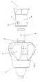
- Figure 1 shows a sectional view of the locking connection between an instrument handle 2 and an instrument insert 4, wherein in FIG 1 only the distal end of the instrument handle 2 and the proximal end of the instrument insert 4 are shown.
- the instrument use 4 has a shaft tube 6, which is located at the proximal End of the instrument insert in a housing part 8 extends and at its proximal end engages in a connection part 10 and in this is fixed.
- the proximal end of the connection part 10 is a Luer connection 12 designed to allow easy connection of the flushing lines to the To clean the shaft tube 6 to allow.
- the housing part 8 is from the proximal end of a connecting part 14 used, which via snap hook 16 in the housing part. 8 is fixed.
- the connecting part 14 is formed so that it next to the arranged at the distal end snap hooks 16 snap hook 18th which extend in the proximal direction and at their proximal free ends radially inward thickenings in Having form of locking projections.
- the instrument handle 2 has a distally extending Housing portion 20, in which on the outer circumference of an annular Locking groove 22 is formed. In this locking groove 22 engage the thickened Portions of the locking tongues 18 for connecting instrument handle 2 and 4 instrument insert.
- a grip sleeve 24 is axial guided in the direction of the longitudinal axis X movable. Inside the Grip sleeve 24 is arranged concentrically to this a closure sleeve 26, which also axially movable in the direction of the longitudinal axis X. the outer circumference of the housing portion 20 is guided.
- the sealing sleeve 26 is formed at its distal end so that they are in one Locked position or secured position the distal ends the locking tongues 18 circumferentially overlaps, so that the locking tongues 18th can not move radially outward and the thickening of the Locking tongues 18 held firmly in engagement with the locking groove 22 in this position become.
- an annular Investment shoulder 28 is formed on the inner circumference of the closure sleeve 26 . Furthermore, on the outer circumference of the housing portion 20 a distally directed abutment shoulder 30 is provided on the outer circumference of the housing portion 20 .
- the abutment shoulder 28 and the abutment shoulder 30 are in the direction the longitudinal axis X spaced from each other and between the two abutment shoulders 28 and 30, a compression spring 32 is arranged.
- the compression spring 32 is designed as a helical spring and concentric arranged to the longitudinal axis X.
- the compression spring 32 presses the closure sleeve 26 via the abutment shoulder 28 in its secured position. To this This ensures that the closure sleeve 26 automatically in the secured position is moved and held in this, so that the Locking tongues 18 can not disengage from the locking groove 22.
- the closure sleeve 26 has a radially outward direction directed projection 34.
- the grip sleeve 24 is at its proximal End radially enlarged on the inner circumference, leaving a proximal directed abutment shoulder 36 is formed.
- a guide element 38 which on the outer circumference of the housing portion 20 in the direction the longitudinal axis X is movably guided closes the grip sleeve 24 at its proximal end. Furthermore, the guide element 38 engages behind the the abutment shoulder 30 forming annular projection 39 at the proximal Page. The projection 38 thus limits the movement of the grip sleeve 24 in the distal direction.
- the projection 34 abuts with its distally directed side surface the contact shoulder 36 inside the grip sleeve 24 at. This causes that on the closure sleeve 26 and the grip sleeve 24 of the compression spring 32 is pressed in the shown secured position.
- the grip sleeve 24 is grasped and moved proximally, whereby on the contact shoulder 26 and the projection 34 the Closure sleeve 26 in the proximal direction against the spring force of Compression spring 32 is moved.
- the distal end of the closure sleeve 26 of the locking tongues 18 disengaged so that they themselves can move radially outward.
- the instrument handle 2 on the grip sleeve 24 and the instrument insert 4 on the housing part 8 and the instrument insert 4 and the instrument handle 2 can in the direction of the longitudinal axis X to each other to be moved.
- the instrument insert 4 with the connection part 10 inserted into the housing portion 20 of the instrument insert is, the proximal end edges of the locking tongues 18 come to rest at the distal end face of the closure sleeve 26.
- FIG. 2 shows a Section view of the locking connection between the instrument handle 2 and Instrument Usage 4.
- a Ball detent connection is provided.
- a sleeve-shaped housing portion 40 extends distally.
- the locking balls 44 have a diameter which is larger as the radial extent of the holes 42 and the wall thickness of Housing section 40 is.
- the instrument insert 4 has a shaft tube 6, which at its proximal end enters a housing part 46.
- the housing part 46 goes at its proximal end into a fixed connection part 48 above.
- a proximal portion of the connecting part 48 is at the Outer circumference formed an annular locking groove 49, in which the locking balls 44 can interlock interlocking. If the detent balls 44 engage in the locking groove 49, the instrument handle 2 and the instrument panel 4 firmly connected.
- a closure sleeve 50 is provided, which on the outer circumference of the connecting part 48 in the longitudinal direction X movable is guided.
- the closure sleeve 50 has a radially inward direction directed projection, which also sliding on the outer circumference of the connecting part 48 is guided.
- the housing part 46 indicates its proximal end a radially outward projection 54 on.
- a compression spring 56 in the form of a helical spring arranged parallel to the longitudinal axis X. The compression spring 56 presses the Closure sleeve 52 proximally into the locked position in which the Holes 42 on the outer circumference of the closure sleeve 50 covered become.
- the closure sleeve 50 is surrounded by a grip sleeve 57, which on Outer circumference of the housing part 46 and the closure sleeve 50 in Longitudinal direction X is movably guided.
- the closure sleeve 50 indicates the position of the projection 52 also an outwardly directed Projection 58, which rests on the inner circumference of the grip sleeve 57.
- On the inner circumference of the grip sleeve 57 is a distally directed abutment shoulder 60 formed, which as a stop for the projection 58th the closure sleeve 50 is used.
- FIG. 2 allows the decoupled movement from locking sleeve 50 and grip sleeve 57.
- instrument handle 2 and instrument insert 4 slide the locking balls 44 initially on the outer circumference of the connecting part 48, wherein they protrude radially outward from the holes 42.
- the Raskugeln 42 come with the proximal end face the closure sleeve 50 in contact and push them against the spring force the compression spring 56 in the distal direction in an unlocked position.
- the projection 58 comes from the contact shoulder 60 of the grip sleeve 57 disengaged.
- the grip sleeve 57 can thus in their original Stay situation and gripped on the grip sleeve 57 instrument insert 4 can easily continue proximally on the instrument handle 2 to be moved.
- the movement the closure sleeve 50 in the proximal direction is replaced by a step 64 limited to the outer periphery of the connecting part 48. If the Projection 52 abuts the step 64, the closure sleeve 50 has the in Fig.
- the embodiment shown in Fig. 2 also has an overload protection for the actuation of a movable element at the distal End of the instrument insert 4.
- an actuating rod 66 is arranged which moves proximally can be, for example, a forceps jaw at the distal end to close the instrument insert 4.
- the proximal end of the Shaft tube 6 has a radially outwardly projecting ring element 68 on.
- a compression spring 42 is arranged, which as Ubedastschutz acts.
- a Force applied to the shaft tube 6 in the proximal direction is at the proximal end of the shaft tube 6 via the ring element 68 on the compression spring 72 and from there to the connecting part 48 and transmitted via this on to the instrument handle 2. If now the force to be transmitted, the spring force of the compression spring 72nd exceeds, this is compressed, and thus the transferable force limited. In this way, sensitive element joints or can Lever of the forceps jaw to be protected against overload.
- the spring constant the compression spring 72 is preferably selected so that in the in the instrument maximum possible compression the spring force around not increased more than 20 to 50%. The configured overload protection can be realized in other instruments, which are not the Having described latching connections.
- Fig. 3 shows the fully locked state of the latching connection as shown in FIG. 2.
- the closure sleeve 50 covers the holes 42, so the locking balls 44 are held securely in the locking groove 49.
- the compression spring 56 holds the closure sleeve 50 and the Grip sleeve 57 in this secured position.
- Fig. 4 shows how the locking connection according to FIGS. 2 and 3 is released.
- the grip sleeve 57 of the instrument insert 4 seized and pulled apart. This is the grip sleeve 57 distally moves and takes over the abutment shoulder 60 and the Projection 58, the closure sleeve 50 so that the closure sleeve 50th is moved away from the holes 42 and releases the locking balls 44, so they can move radially outward. So come the Detent balls 44 of the locking groove 49 disengaged and the instrument insert 4 can be pulled out of the instrument handle 2.
- the grip sleeve 57 simultaneously acts as a rotary wheel and is non-rotatable guided on the housing part 46 of the instrument insert. This makes possible, that of the entire instrument use by rotation of the Grip sleeve 57 about the longitudinal axis X with respect to the instrument handle 2 can be turned. In this case, the locking balls 44 in the rotate annular detent groove 49.
- Fig. 5 shows a non-sectional view of the proximal end of the Instrument insert 4 and the distal end of the instrument handle 2 according to the embodiments shown in FIGS. 2 to 4.
- the locking groove 49 is formed wavy, the means it has a corrugated or jagged in particular in the axial direction Edge. This causes a slight load when turning the rotary wheel, or the grip sleeve 57 relative to the instrument handle 2 radial locking positions are noticeable, so that the instrument insert 4 detent with respect to the instrument handle 2 twisted can be.
- handle sleeve 57 could and closure sleeve 50 in a corresponding embodiment of the instrument handle 2 are arranged.
Landscapes
- Health & Medical Sciences (AREA)
- Surgery (AREA)
- Life Sciences & Earth Sciences (AREA)
- Biomedical Technology (AREA)
- Nuclear Medicine, Radiotherapy & Molecular Imaging (AREA)
- Engineering & Computer Science (AREA)
- Ophthalmology & Optometry (AREA)
- Heart & Thoracic Surgery (AREA)
- Medical Informatics (AREA)
- Molecular Biology (AREA)
- Animal Behavior & Ethology (AREA)
- General Health & Medical Sciences (AREA)
- Public Health (AREA)
- Veterinary Medicine (AREA)
- Surgical Instruments (AREA)
Abstract
Description
- Fig. 1
- eine Schnittansicht einer erfindungsgemäßen Rastverbindung zwischen Instrumenteneinsatz und Instrumentenhandhabe gemäß einer ersten Ausführungsform,
- Fig. 2
- eine Schnittansicht einer Rastverbindung zwischen Instrumentenhandhabe und Instrumenteneinsatz gemäß einer zweiten Ausführungsform während des Zusammensetzens,
- Fig. 3
- die Rastverbindung gemäß Fig. 2 im verriegelten Zustand,
- Fig. 4
- die Rastverbindung gemäß Fig. 2 und 3 beim Trennen von Instrumenteneinsatz und Instrumentenhandhabe, und
- Fig. 5
- schematisch eine Außenansicht des proximalen Ende des Instrumenteneinsatzes gemäß Fig. 2 bis 4.
- 2
- Instrumentenhandhabe
- 4
- Instrumenteneinsatz
- 6
- Schaftrohr
- 8
- Gehäuseteil
- 10
- Anschlussteil
- 12
- Lüranschluss
- 14
- Verbindungsteil
- 16
- Schnapphaken
- 18
- Rastzungen
- 20
- Gehäuseabschnitt
- 22
- Rastnut
- 24
- Griffhülse
- 26
- Verschlusshülse
- 28
- Anlageschulter
- 30
- Anlageschulter
- 32
- Druckfeder
- 34
- Vorsprung
- 36
- Anlageschulter
- 38
- Führungselement
- 39
- Vorsprung
- 40
- Gehäuseabschnitt
- 42
- Bohrung
- 44
- Rastkugeln
- 46
- Gehäuseteil
- 48
- Verbindungsteil
- 49
- Rastnut
- 50
- Verschlusshülse
- 52
- Vorsprung
- 54
- Auskragung
- 56
- Druckfeder
- 57
- Griffhülse
- 58
- Auskragung
- 60
- Anlageschulter
- 62
- Auskragung
- 64
- Stufe
- 66
- Betätigungsstange
- 68
- Ringelement
- 70
- Anlageschulter
- 72
- Druckfeder
- X
- Längsachse
Claims (14)
- Medizinisches Instrument mit einem Instrumenteneinsatz (4) und einer Instrumentenhandhabe (2), welche über eine Rastverbindung lösbar miteinander verbindbar sind, wobei ein Griffelement (24; 57) sowie ein Verschlusselement (26; 50) zur Sicherung der Rastverbindung vorgesehen sind und das Verschlusselement (26; 50) sowohl durch Bewegung des Griffelementes (24; 57) als auch unabhängig von einer Bewegung des Griffelementes (24; 57) in eine entsicherte Position bewegbar ist.
- Medizinisches Instrument nach Anspruch 1, bei welchem die Rastverbindung zumindest ein bewegliches Rastelement (18; 44) aufweist und das Verschlusselement (26; 50) in einer gesicherten Position das Rastelement (18; 44) blockiert und in einer entsicherten Position das Rastelement (18; 44) freigibt.
- Medizinisches Instrument nach Anspruch 2, bei welchem das Rastelement eine Rastkugel (44) ist.
- Medizinisches Instrument nach Anspruch 2, bei welchem das Rastelement eine federnde Rastzunge (18) ist.
- Medizinisches Instrument nach einem der Ansprüche 2 bis 4, bei welchem die Rastelemente (18; 44) in eine korrespondierende ringförmige Rastnut (22; 49)eingreifen.
- Medizinisches Instrument nach einem der vorangehenden Ansprüche, bei welchem das Griffelement (24; 57) und das Verschlusselement (26; 50) in Richtung der Längsachse X des Instrumenteneinsatzes (4) bewegbar sind.
- Medizinisches Instrument nach einem der vorangehenden Ansprüche, bei welchem das Verschlusselement (26; 50) durch Federkraft in der gesicherten Position gehalten wird.
- Medizinisches Instrument nach einem der vorangehenden Ansprüche, bei welchem das Verschlusselement (26; 50) als Verschlusshülse und das Griffelement (24; 57) als Griffhülse ausgebildet sind, welche in Richtung der Längsachse X des Instrumenteneinsatzes (4) beweglich geführt sind, wobei die Verschlusshülse (26; 50) im Inneren der Griffhülse (24; 57) angeordnet ist.
- Medizinisches Instrument nach Anspruch 8, bei welchem die Verschlusshülse (26; 50) zumindest eine Anlageschulter (34; 58) aufweist, welche von einer an der Griffhülse ausgebildeten Anlageschulter (36; 60) lediglich an einer in Bewegungsrichtung zu der entsicherten Position rückwärtigen Fläche hintergriffen wird.
- Medizinisches Instrument nach einem der vorangehenden Ansprüche, bei welchem die Rastverbindung ein Rastelement (44) aufweist, welches zur Verbindung von Instrumenteneinsatz (4) und Instrumentenhandhabe (2) in eine korrespondierenden Rastnut (49) eingreift, welche axial einen gewellten oder gezackten Rand aufweist.
- Medizinisches Instrument nach einem der vorangehenden Ansprüche, bei welchem das Griffelement (57) und das Verschlusselement (50) am proximalen Ende des Instrumenteneinsatzes (4) angeordnet sind.
- Medizinisches Instrument nach einem der vorangehenden Ansprüche, bei welchem das Griffelement (57) drehfest mit dem Instrumenteneinsatz (4) verbunden ist.
- Medizinisches Instrument nach einem der vorangehenden Ansprüche, bei welchem der Instrumenteneinsatz (4) ein Schaftrohr (6), eine im Inneren des Schaftrohres angeordnete Betätigungsstange (66) und zumindest ein am distalen Ende angeordnetes über die Betätigungsstange (66) bewegliches Element aufweist, wobei im Kraftfluss zur Bewegung des beweglichen Elementes zumindest ein Federelement (72) als Überlastsicherung angeordnet ist.
- Medizinisches Instrument nach Anspruch 13, bei welchem das Schaftrohr (6) an seinem proximalen Ende in einem Verbindungselement (48) zur Verbindung mit einer Instrumentenhandhabe (2) gelagert ist und das Schaftrohr (6) sich in proximaler Richtung an dem Verbindungselement (48) über ein axial wirkendes Federelement (72) abstützt.
Applications Claiming Priority (2)
| Application Number | Priority Date | Filing Date | Title |
|---|---|---|---|
| DE10357103 | 2003-12-06 | ||
| DE10357103A DE10357103A1 (de) | 2003-12-06 | 2003-12-06 | Medizinisches Instrument |
Publications (2)
| Publication Number | Publication Date |
|---|---|
| EP1537828A1 true EP1537828A1 (de) | 2005-06-08 |
| EP1537828B1 EP1537828B1 (de) | 2009-07-08 |
Family
ID=34442484
Family Applications (1)
| Application Number | Title | Priority Date | Filing Date |
|---|---|---|---|
| EP04025437A Expired - Lifetime EP1537828B1 (de) | 2003-12-06 | 2004-10-26 | Medizinisches Instrument mit Kupplung für Instrumenteneinsatz |
Country Status (4)
| Country | Link |
|---|---|
| US (1) | US7931667B2 (de) |
| EP (1) | EP1537828B1 (de) |
| AT (1) | ATE435617T1 (de) |
| DE (2) | DE10357103A1 (de) |
Cited By (1)
| Publication number | Priority date | Publication date | Assignee | Title |
|---|---|---|---|---|
| CN111643201A (zh) * | 2020-07-02 | 2020-09-11 | 西安交通大学口腔医院 | 一种口腔牙齿种植使用的夹持装置 |
Families Citing this family (5)
| Publication number | Priority date | Publication date | Assignee | Title |
|---|---|---|---|---|
| JP4056989B2 (ja) * | 2003-06-24 | 2008-03-05 | オリンパス株式会社 | 内視鏡処置具 |
| DE102008004545B4 (de) * | 2008-01-15 | 2017-08-24 | Accuride International Gmbh | Linearführungssystem mit Selbsteinzug |
| JP2014087378A (ja) * | 2011-02-23 | 2014-05-15 | Olympus Medical Systems Corp | 内視鏡用処置具 |
| US20150173944A1 (en) * | 2013-12-23 | 2015-06-25 | Novartis Ag | Systems and methods for attaching a surgical instrument tip |
| CN110051410B (zh) * | 2019-05-15 | 2022-02-22 | 成都五义医疗科技有限公司 | 一种可拆洗重用的细长轴组件及其手术器械 |
Citations (6)
| Publication number | Priority date | Publication date | Assignee | Title |
|---|---|---|---|---|
| US4577875A (en) * | 1982-10-29 | 1986-03-25 | Miyakawa Industry Co., Ltd. | Exchange chuck for a tool |
| DE3934610A1 (de) * | 1989-10-17 | 1991-04-25 | Aesculap Ag | Schnellkupplung fuer chirurgische instrumente |
| US5505737A (en) * | 1994-07-01 | 1996-04-09 | Midas Rex Pneumatic Tools, Inc. | Quick release coupling for a dissecting tool |
| DE19514098A1 (de) * | 1995-04-13 | 1996-10-17 | Storz Karl Gmbh & Co | Kupplung für Rohrschaftinstrumente |
| DE19918638A1 (de) * | 1999-04-23 | 2000-11-30 | Axel Kirsch | Anschlußstück für einen Bohrer zum Erzeugen von Bohrungen in Knochengewebe, Bohrer und Bohrgerät |
| WO2001001870A1 (de) * | 1999-07-01 | 2001-01-11 | Karl Storz Gmbh & Co. Kg | Medizinisches, insbesondere chirurgisches instrument |
Family Cites Families (16)
| Publication number | Priority date | Publication date | Assignee | Title |
|---|---|---|---|---|
| US3465835A (en) * | 1967-12-05 | 1969-09-09 | Lawrence R Krivit | Pin-driving device |
| US4692073A (en) * | 1985-02-25 | 1987-09-08 | Martindell J Richard | Handle adapter and chuck apparatus for power bits |
| DE3506695A1 (de) * | 1985-02-26 | 1986-08-28 | Robert Bosch Gmbh, 7000 Stuttgart | Bohrhammer |
| IT1201872B (it) * | 1986-09-30 | 1989-02-02 | Orthofix Srl | Mandrino autoserrante per trapani ed apparecchiature simili, particolarmente adatto per trapani portatili ad uso chirurgico |
| DE8709151U1 (de) * | 1987-07-02 | 1987-11-12 | GIP Gastrointestinale Produkte Vertriebs GmbH, 83355 Grabenstätt | Endoskopische Vorrichtung |
| US5009661A (en) * | 1989-04-24 | 1991-04-23 | Michelson Gary K | Protective mechanism for surgical rongeurs |
| US4998351A (en) * | 1989-06-14 | 1991-03-12 | Hartmeister Ruben J | Power driven hand tool assembly |
| US5441494A (en) * | 1993-07-29 | 1995-08-15 | Ethicon, Inc. | Manipulable hand for laparoscopy |
| US5569284A (en) * | 1994-09-23 | 1996-10-29 | United States Surgical Corporation | Morcellator |
| AUPN263895A0 (en) * | 1995-04-28 | 1995-05-25 | Bradley, Christopher Mark | Apparatus and method for producing bone graft material |
| US5957634A (en) * | 1997-03-07 | 1999-09-28 | Carpinetti; David J. | Quick change drill extender system |
| DE19809120C1 (de) * | 1998-03-04 | 1999-08-19 | Aesculap Ag & Co Kg | Chirurgisches Rohrschaftinstrument |
| DE19935042B4 (de) * | 1999-07-26 | 2004-02-05 | Aesculap Ag & Co. Kg | Chirurgisches Rohrschaftinstrument |
| DE10005910B4 (de) * | 2000-02-10 | 2005-10-13 | Robert Bosch Gmbh | Handwerkzeugmaschine mit einem auswechselbaren Werkzeughalter |
| DE10047021A1 (de) * | 2000-09-22 | 2002-04-18 | Bosch Gmbh Robert | Handwerkzeugmachine mit einer abnehmbaren Werkzeughalterung |
| US20040056435A1 (en) * | 2001-02-15 | 2004-03-25 | Sanjeev Bedi | Quick-connect mechanism |
-
2003
- 2003-12-06 DE DE10357103A patent/DE10357103A1/de not_active Withdrawn
-
2004
- 2004-10-26 DE DE502004009711T patent/DE502004009711D1/de not_active Expired - Lifetime
- 2004-10-26 AT AT04025437T patent/ATE435617T1/de active
- 2004-10-26 EP EP04025437A patent/EP1537828B1/de not_active Expired - Lifetime
- 2004-12-06 US US11/005,143 patent/US7931667B2/en not_active Expired - Fee Related
Patent Citations (6)
| Publication number | Priority date | Publication date | Assignee | Title |
|---|---|---|---|---|
| US4577875A (en) * | 1982-10-29 | 1986-03-25 | Miyakawa Industry Co., Ltd. | Exchange chuck for a tool |
| DE3934610A1 (de) * | 1989-10-17 | 1991-04-25 | Aesculap Ag | Schnellkupplung fuer chirurgische instrumente |
| US5505737A (en) * | 1994-07-01 | 1996-04-09 | Midas Rex Pneumatic Tools, Inc. | Quick release coupling for a dissecting tool |
| DE19514098A1 (de) * | 1995-04-13 | 1996-10-17 | Storz Karl Gmbh & Co | Kupplung für Rohrschaftinstrumente |
| DE19918638A1 (de) * | 1999-04-23 | 2000-11-30 | Axel Kirsch | Anschlußstück für einen Bohrer zum Erzeugen von Bohrungen in Knochengewebe, Bohrer und Bohrgerät |
| WO2001001870A1 (de) * | 1999-07-01 | 2001-01-11 | Karl Storz Gmbh & Co. Kg | Medizinisches, insbesondere chirurgisches instrument |
Cited By (1)
| Publication number | Priority date | Publication date | Assignee | Title |
|---|---|---|---|---|
| CN111643201A (zh) * | 2020-07-02 | 2020-09-11 | 西安交通大学口腔医院 | 一种口腔牙齿种植使用的夹持装置 |
Also Published As
| Publication number | Publication date |
|---|---|
| US7931667B2 (en) | 2011-04-26 |
| US20050125026A1 (en) | 2005-06-09 |
| ATE435617T1 (de) | 2009-07-15 |
| DE502004009711D1 (de) | 2009-08-20 |
| EP1537828B1 (de) | 2009-07-08 |
| DE10357103A1 (de) | 2005-07-07 |
Similar Documents
| Publication | Publication Date | Title |
|---|---|---|
| EP1537829B1 (de) | Medizinisches Instrument mit Instrumenteneinsatz und Mittel zur Blockierung des beweglichen Griffteils | |
| EP0537452B1 (de) | Medizinische Zange | |
| DE69702289T2 (de) | Gelenkanordnung für chirurgische Instrumente | |
| EP2704646B1 (de) | Chirurgisches kupplungssystem und chirurgisches antriebssystem | |
| EP1239777B1 (de) | Medizinisches instrument mit abnehmbarem werkzeug | |
| EP2612609B1 (de) | Medizinisches Instrument | |
| EP3410965B1 (de) | Instrument zum führen eines stabs in eine implantataufnahme | |
| EP3411099B1 (de) | Injektionsvorrichtung | |
| EP3380026B1 (de) | Handhabungsinstrument für eine knochenschraube | |
| DE102013112386A1 (de) | Verschlussvorrichtung mit Betätigungselement | |
| DE3818808A1 (de) | Verschluss zur festlegung eines aussenteiles auf einem innenteil, insbesondere der kupplungshuelse einer gelenkwelle einer landmaschine auf der zapfwelle eines schleppers | |
| EP0860148A2 (de) | Bajonettkupplung zum lösbaren Verbinden zweier Rohrschaftinstrumente oder -instrumententeile | |
| DE102009027438A1 (de) | Synchronisierung für ein Schaltgetriebe | |
| DE102004053538A1 (de) | Kupplungsvorrichtung zum Verbinden von Leitungen und Kraftfahrzeug mit einer derartigen Kupplungsvorrichtung | |
| DE202011108753U1 (de) | Handgeführtes Gerät mit einem Bedienungshebel | |
| EP2489315A1 (de) | Medizinisches Instrument | |
| EP1537828B1 (de) | Medizinisches Instrument mit Kupplung für Instrumenteneinsatz | |
| EP1709931B1 (de) | Motorelement, insbesondere dentalmedizinisches Handstück mit einer lösbaren Kupplung für einen Werkzeughalter | |
| DE19501882C2 (de) | Medizinisches Instrument | |
| DE1791013C2 (de) | Kupplung für den Anschluß eines zahnärztlichen Hand- oder Winkelstückes an einen als Kleinstmotor ausgebildeten elektrischen Antriebsmotor | |
| EP2904979B1 (de) | Montageverfahren für ein mikrochirurgisches Instrument | |
| DE10236274B4 (de) | Modulares Zangensystem | |
| DE102009060714B4 (de) | Saug-Spül-Handgriff für ein endoskopisches Instrument | |
| DE9317664U1 (de) | Medizinisches Instrument mit einem zentralen Arbeitsstab und mit einem Handgriff | |
| EP4355390B1 (de) | Sicherheitskanülenanordnung |
Legal Events
| Date | Code | Title | Description |
|---|---|---|---|
| PUAI | Public reference made under article 153(3) epc to a published international application that has entered the european phase |
Free format text: ORIGINAL CODE: 0009012 |
|
| AK | Designated contracting states |
Kind code of ref document: A1 Designated state(s): AT BE BG CH CY CZ DE DK EE ES FI FR GB GR HU IE IT LI LU MC NL PL PT RO SE SI SK TR |
|
| AX | Request for extension of the european patent |
Extension state: AL HR LT LV MK |
|
| 17P | Request for examination filed |
Effective date: 20050428 |
|
| AKX | Designation fees paid |
Designated state(s): AT CH DE FR GB LI |
|
| 17Q | First examination report despatched |
Effective date: 20070507 |
|
| GRAP | Despatch of communication of intention to grant a patent |
Free format text: ORIGINAL CODE: EPIDOSNIGR1 |
|
| GRAS | Grant fee paid |
Free format text: ORIGINAL CODE: EPIDOSNIGR3 |
|
| GRAA | (expected) grant |
Free format text: ORIGINAL CODE: 0009210 |
|
| AK | Designated contracting states |
Kind code of ref document: B1 Designated state(s): AT CH DE FR GB LI |
|
| REG | Reference to a national code |
Ref country code: GB Ref legal event code: FG4D Free format text: NOT ENGLISH |
|
| REG | Reference to a national code |
Ref country code: CH Ref legal event code: EP |
|
| REG | Reference to a national code |
Ref country code: CH Ref legal event code: NV Representative=s name: ISLER & PEDRAZZINI AG |
|
| REF | Corresponds to: |
Ref document number: 502004009711 Country of ref document: DE Date of ref document: 20090820 Kind code of ref document: P |
|
| PLBE | No opposition filed within time limit |
Free format text: ORIGINAL CODE: 0009261 |
|
| STAA | Information on the status of an ep patent application or granted ep patent |
Free format text: STATUS: NO OPPOSITION FILED WITHIN TIME LIMIT |
|
| 26N | No opposition filed |
Effective date: 20100409 |
|
| REG | Reference to a national code |
Ref country code: FR Ref legal event code: PLFP Year of fee payment: 13 |
|
| REG | Reference to a national code |
Ref country code: FR Ref legal event code: PLFP Year of fee payment: 14 |
|
| REG | Reference to a national code |
Ref country code: FR Ref legal event code: PLFP Year of fee payment: 15 |
|
| PGFP | Annual fee paid to national office [announced via postgrant information from national office to epo] |
Ref country code: AT Payment date: 20201016 Year of fee payment: 17 Ref country code: CH Payment date: 20201022 Year of fee payment: 17 Ref country code: FR Payment date: 20201020 Year of fee payment: 17 Ref country code: GB Payment date: 20201022 Year of fee payment: 17 |
|
| REG | Reference to a national code |
Ref country code: DE Ref legal event code: R084 Ref document number: 502004009711 Country of ref document: DE |
|
| REG | Reference to a national code |
Ref country code: CH Ref legal event code: PL |
|
| REG | Reference to a national code |
Ref country code: AT Ref legal event code: MM01 Ref document number: 435617 Country of ref document: AT Kind code of ref document: T Effective date: 20211026 |
|
| GBPC | Gb: european patent ceased through non-payment of renewal fee |
Effective date: 20211026 |
|
| PG25 | Lapsed in a contracting state [announced via postgrant information from national office to epo] |
Ref country code: GB Free format text: LAPSE BECAUSE OF NON-PAYMENT OF DUE FEES Effective date: 20211026 |
|
| PG25 | Lapsed in a contracting state [announced via postgrant information from national office to epo] |
Ref country code: LI Free format text: LAPSE BECAUSE OF NON-PAYMENT OF DUE FEES Effective date: 20211031 Ref country code: CH Free format text: LAPSE BECAUSE OF NON-PAYMENT OF DUE FEES Effective date: 20211031 Ref country code: AT Free format text: LAPSE BECAUSE OF NON-PAYMENT OF DUE FEES Effective date: 20211026 |
|
| PG25 | Lapsed in a contracting state [announced via postgrant information from national office to epo] |
Ref country code: FR Free format text: LAPSE BECAUSE OF NON-PAYMENT OF DUE FEES Effective date: 20211031 |
|
| PGFP | Annual fee paid to national office [announced via postgrant information from national office to epo] |
Ref country code: DE Payment date: 20221025 Year of fee payment: 19 |
|
| REG | Reference to a national code |
Ref country code: DE Ref legal event code: R119 Ref document number: 502004009711 Country of ref document: DE |
|
| PG25 | Lapsed in a contracting state [announced via postgrant information from national office to epo] |
Ref country code: DE Free format text: LAPSE BECAUSE OF NON-PAYMENT OF DUE FEES Effective date: 20240501 |