EP1537648B1 - Reglung einer elektrischen reluktanzmaschine - Google Patents
Reglung einer elektrischen reluktanzmaschine Download PDFInfo
- Publication number
- EP1537648B1 EP1537648B1 EP03750914.8A EP03750914A EP1537648B1 EP 1537648 B1 EP1537648 B1 EP 1537648B1 EP 03750914 A EP03750914 A EP 03750914A EP 1537648 B1 EP1537648 B1 EP 1537648B1
- Authority
- EP
- European Patent Office
- Prior art keywords
- electrical signal
- rotor
- induced
- armature
- winding
- Prior art date
- Legal status (The legal status is an assumption and is not a legal conclusion. Google has not performed a legal analysis and makes no representation as to the accuracy of the status listed.)
- Expired - Lifetime
Links
- 238000004804 winding Methods 0.000 claims description 272
- 238000000034 method Methods 0.000 claims description 68
- 230000008859 change Effects 0.000 claims description 50
- 230000004907 flux Effects 0.000 claims description 25
- 230000001419 dependent effect Effects 0.000 claims description 21
- 238000001514 detection method Methods 0.000 claims description 20
- 239000004020 conductor Substances 0.000 claims description 16
- 239000011295 pitch Substances 0.000 claims description 13
- 238000005070 sampling Methods 0.000 claims description 11
- 230000004044 response Effects 0.000 claims description 9
- 238000012544 monitoring process Methods 0.000 claims description 8
- 230000005284 excitation Effects 0.000 description 37
- 230000007704 transition Effects 0.000 description 14
- 238000004519 manufacturing process Methods 0.000 description 12
- 238000005259 measurement Methods 0.000 description 12
- 230000008901 benefit Effects 0.000 description 11
- 238000010586 diagram Methods 0.000 description 11
- 230000000630 rising effect Effects 0.000 description 11
- 230000008878 coupling Effects 0.000 description 9
- 238000010168 coupling process Methods 0.000 description 9
- 238000005859 coupling reaction Methods 0.000 description 9
- 239000003990 capacitor Substances 0.000 description 8
- 230000005355 Hall effect Effects 0.000 description 7
- 230000004069 differentiation Effects 0.000 description 6
- 230000003044 adaptive effect Effects 0.000 description 5
- 230000001976 improved effect Effects 0.000 description 5
- 230000000694 effects Effects 0.000 description 4
- 238000001914 filtration Methods 0.000 description 4
- 230000001965 increasing effect Effects 0.000 description 4
- 230000000977 initiatory effect Effects 0.000 description 4
- 230000009286 beneficial effect Effects 0.000 description 3
- 238000010276 construction Methods 0.000 description 3
- 238000013461 design Methods 0.000 description 3
- 230000003287 optical effect Effects 0.000 description 3
- 230000003252 repetitive effect Effects 0.000 description 3
- 229910000831 Steel Inorganic materials 0.000 description 2
- 238000004364 calculation method Methods 0.000 description 2
- 230000003750 conditioning effect Effects 0.000 description 2
- 230000007423 decrease Effects 0.000 description 2
- 238000000605 extraction Methods 0.000 description 2
- 238000009499 grossing Methods 0.000 description 2
- 238000003475 lamination Methods 0.000 description 2
- 238000012545 processing Methods 0.000 description 2
- 230000002441 reversible effect Effects 0.000 description 2
- 239000004065 semiconductor Substances 0.000 description 2
- 230000003068 static effect Effects 0.000 description 2
- 239000010959 steel Substances 0.000 description 2
- 238000013459 approach Methods 0.000 description 1
- 238000006243 chemical reaction Methods 0.000 description 1
- 238000012937 correction Methods 0.000 description 1
- 230000003247 decreasing effect Effects 0.000 description 1
- 230000005669 field effect Effects 0.000 description 1
- 230000036039 immunity Effects 0.000 description 1
- 230000001939 inductive effect Effects 0.000 description 1
- 238000002347 injection Methods 0.000 description 1
- 239000007924 injection Substances 0.000 description 1
- 238000003780 insertion Methods 0.000 description 1
- 230000037431 insertion Effects 0.000 description 1
- 238000009533 lab test Methods 0.000 description 1
- 230000007774 longterm Effects 0.000 description 1
- 239000000696 magnetic material Substances 0.000 description 1
- 238000013178 mathematical model Methods 0.000 description 1
- 230000004048 modification Effects 0.000 description 1
- 238000012986 modification Methods 0.000 description 1
- 238000007383 open-end spinning Methods 0.000 description 1
- 230000035699 permeability Effects 0.000 description 1
- 239000000243 solution Substances 0.000 description 1
- 238000012360 testing method Methods 0.000 description 1
Images


Classifications
-
- H—ELECTRICITY
- H02—GENERATION; CONVERSION OR DISTRIBUTION OF ELECTRIC POWER
- H02P—CONTROL OR REGULATION OF ELECTRIC MOTORS, ELECTRIC GENERATORS OR DYNAMO-ELECTRIC CONVERTERS; CONTROLLING TRANSFORMERS, REACTORS OR CHOKE COILS
- H02P6/00—Arrangements for controlling synchronous motors or other dynamo-electric motors using electronic commutation dependent on the rotor position; Electronic commutators therefor
- H02P6/14—Electronic commutators
- H02P6/16—Circuit arrangements for detecting position
- H02P6/18—Circuit arrangements for detecting position without separate position detecting elements
- H02P6/182—Circuit arrangements for detecting position without separate position detecting elements using back-emf in windings
-
- H—ELECTRICITY
- H02—GENERATION; CONVERSION OR DISTRIBUTION OF ELECTRIC POWER
- H02P—CONTROL OR REGULATION OF ELECTRIC MOTORS, ELECTRIC GENERATORS OR DYNAMO-ELECTRIC CONVERTERS; CONTROLLING TRANSFORMERS, REACTORS OR CHOKE COILS
- H02P1/00—Arrangements for starting electric motors or dynamo-electric converters
- H02P1/16—Arrangements for starting electric motors or dynamo-electric converters for starting dynamo-electric motors or dynamo-electric converters
- H02P1/163—Arrangements for starting electric motors or dynamo-electric converters for starting dynamo-electric motors or dynamo-electric converters for starting an individual reluctance motor
Definitions
- This invention relates to control of electrical machines, and is concerned more particularly, but not exclusively, with control of electric machines without a mechanical shaft position sensor.
- Figures 1a and 1b show a conventional two-phase switched reluctance motor comprising a stator 2 having two pairs 3, 4 of oppositely disposed inwardly directed salient poles provided with two pairs 5, 6 of energising windings corresponding to the two phases, and a rotor 7 having a single pair 8 of oppositely disposed outwardly directed salient poles without windings.
- Each of the four energising windings is wound about its corresponding pole, as indicated by the symbols Y-Y denoting two diametrically opposite portions of each winding of the winding pair 6 and the symbols X-X denoting two diametrically opposite portions of each winding of the winding pair 5.
- An excitation circuit (not shown) is provided for rotating the rotor 7 within the stator 2 by alternately energising the stator windings in synchronism with rotation of the rotor so that torque is developed by the tendency of the rotor 7 to arrange itself in a position of minimum reluctance within the magnetic field produced by the windings, as will be described in more detail below.
- Such a variable reluctance motor offers the advantage over a conventional wound rotor motor that a commutator and brushes, which are wearing parts, are not required for supply of current to the rotor. Furthermore other advantages are provided because there are no conductors on the rotor and high-cost permanent magnets are not required.
- the winding 11 may be wound so that one part of the winding on one side of the rotor 7 fills a stabr slot 12 defined between adjacent poles of the pole pairs 3, 4, and another part of the winding 11 on the diametrically opposite side of the rotor 7 fills a stator slot 13 defined between two further adjacent poles of the pole pairs 3, 4.
- the winding 10 has corresponding parts filling diametrically opposed stator slots 14 and 15.
- the winding 10 which may be termed the field winding
- the winding 11 which may be termed the armature winding
- the need to supply the armature winding with alternating current in such a motor can result in an excitation circuit of high complexity and cost.
- WO 98/05112 discloses a fully pitched flux-switching variable reluctance motor having a four-pole stator 2 which, as shown diagrammatically in Figure 3a , is provided with a field winding, 10 and an armature winding 11 each of which is split into two coils 22 and 23 or 24 and 25 closely coupled (with a coupling which is substantially independent of rotor position) and wound so that diametrically opposite portions of both coils are disposed within diametrically opposite stator slots.
- Figure 3b shows a generalised circuit diagram for energising the armature coils 24 and 25.
- the coils 24 and 25 are connected within the circuit so that direct current supply to the terminals 26 and 27 flows through both coils 24 and 25 in the same direction so as to generate magnetomotive forces in opposite directions as a result of the opposite winding of the coils.
- Switches 28 and 29, which may comprise field effect transistors or insulated gate bipolar transistors for example, are connected in series with the coils 24 and 25 and are switched alternately to effect alternate energisation of the coils 24 and 25 so as to provide the required magnetomotive forces acting in opposite directions.
- the armature winding is made up of two closely coupled coils which enables each coil to be energised with current in only one direction so that relatively simple excitation circuitry can be used.
- a similar arrangement may be provided in an electrical alternator.
- a position sensing means is required to determine the position of the rotor and hence determine the correct state of the switches 28 and 29 for continuous rotation in the required direction.
- the position sensing means could be provided by an optical sensor mounted on the stator of the machine, observing the rotation of a coded disc with reflective or transparent sections. The optical sensor provides an electrical signal which varies in synchronism with the rotation of the rotor.
- the sensor on the stator may be responsive to magnetic polarity such as a Hall effect device and the coded disc on the rotor would contain a magnetic pattern representative of the rotor teeth. Rotation of the coded magnetic disc along with the rotor creates an electrical signal in the stationary sensor which varies in synchronism with the rotation of the rotor.
- Many other forms of position sensing means are known to those skilled in the art but they all suffer from the problem of mechanical alignment errors.
- the stationary sensor must be mounted to the stator of the machine at a known or pre-defined position.
- the coded disc must also be mounted on the rotor at a known or pre-defined angular position with respect to the rotor poles. This requires manufacturing processes of a high degree of accuracy which are not therefore easy to implement at low cost.
- Such position sensing arrangements are commonly used but have significant mechanical complexity and are not always of low manufacturing cost. Furthermore the alignment of the coded sensor disc to the rotor and the positioning of the electronic pick-up (optical or Hall effect) on the stator must be achieved with precision as the timing of the switching with respect to the rotor position has a direct impact on the performance of the motor. Such alignment is of even greater significance as the running speed of the rotor is increased.
- a system of rotor position detection which is based entirely on direct or indirect electrical measurements on the stator or its electrical windings is preferred as there is no possibility for mechanical error.
- Preferred embodiments of the present invention seek to overcome the above disadvantages of the prior art and seek in particular to provide an electrical machine which has simple control circuitry and has a position sensing means which operates without the requirement of a coded disc on the rotor or sensing device mounted in a specific mechanical position with respect to the stator of the machine and does not require complex electronic circuitry and can work in a motor in which the self inductance of the windings does not vary significantly with position.
- US 6140729 discloses a switched reluctance motor according to the preamble of claim 1.
- the present invention is defined in claim 1 and claim 22.
- said stator has a plurality of stator poles, and at least one said armature winding is wound with a pitch corresponding to a plurality of stator pole pitches.
- said field magnet means includes at least one field winding adapted to be connected in series or in parallel with a circuit containing at least one said armature winding.
- the position sensing means may be adapted to detect at least one mutually induced first electrical signal from at least one said field winding.
- This provides the advantage of simplifying the control circuitry by allowing unidirectional energisation to be applied to the or each field winding and energisation of changing direction to be applied to the or each armature winding.
- the position sensing means is adapted to detect when at least one said mutually induced first electrical signal passes through at least one threshold value to produce at least one second electrical signal.
- the position sensing means may be adapted to detect when at least one mutually induced first electrical signal passes through at least one respective threshold value when an electrical winding of the machine is energized with substantially uniform voltage and/or when said winding is not energized the voltage being a requirement of normal operation of the machine to convert electrical energy into mechanical energy and/or mechanical energy into electrical energy.
- the position sensing means may be adapted to determine when to begin and/or end energisation of at least one said armature winding by determining relative proportions of time for which at least one mutually induced first electrical signal is greater than or less than at least one respective threshold value in at least one winding of the machine during a predetermined period of rotation of said rotor.
- the position sensing means may be adapted to control timing of energisation of at least one said armature winding to maintain relative proportions of time of at least one mutually induced first electrical signal being greater than or less than at least one respective threshold value in at least one winding of the machine within predetermined limits.
- the predetermined limits may be adapted to vary in dependence upon output performance of said machine.
- the position sensing means may be adapted to control timing of said energisation by means of at least one error signal input to said control means.
- the position sensing means may be adapted to selectively control timing of said energisation in response to failure to detect at least one mutually induced first electrical signal passing through a threshold value during a predetermined period.
- the position sensing means may be adapted to detect when at least one said mutually induced first electrical signal passes through at least one respective threshold value to produce at least one said second electrical signal, at least one said threshold value being a function of an average value of the corresponding said mutually induced first electrical signal.
- the position sensing means may be adapted to extract at least one mutually induced first electrical signal dependent on rotational position of said rotor relative to said stator, from the rate of change of current occurring in an electrical winding of the machine arising as a result of the existence of a voltage across one or more other of the said electrical windings of the machine.
- the position sensing means may include at least one respective coil adapted to be magnetically coupled to a magnetic field generated by a conductor carrying the current passing through at least one said winding.
- the position sensing means is adapted to obtain data relating to at least one said mutually induced first electrical signal and compare said data with data relating to at least one known rotor position.
- the position sensing means may be adapted to provide at least one said second electrical signal representative of rotational position of the rotor at standstill by determining at least one mutually induced first electrical signal in at least one electrical winding when at least one other electrical winding of the machine is energised.
- the control means may be adapted to cause said rotor to move relative to said stator to a position of stable equilibrium in response to at least one second electrical signal from said position sensing means generated at standstill of said rotor.
- the position sensing means may be adapted to indicate the nearest position of stable equilibrium of said rotor relative to said stator by observing the respective mutually induced first electrical signal in at least one said electrical winding when at least one other electrical winding of the machine is energized.
- the position sensing means may be adapted to monitor at least one said mutually induced first electrical signal by intermittently sampling said signal.
- the position sensing means may be adapted to monitor at least one said second electrical signal by intermittently sampling said signal.
- the method may further comprise the step of detecting when at least one mutually induced first electrical signal passes through at least one respective threshold value when an electrical winding of the machine is energized with substantially uniform voltage and/or when said winding is not energized the voltage being a requirement of normal operation of the machine to convert electrical energy into mechanical energy and/or mechanical energy into electrical energy.
- the method may further comprise the step of determining when to begin and/or end energisation of at least one said armature winding by determining relative proportions of time for which at least one mutually induced first electrical signal is greater than or less than at least one respective threshold value in at least one winding of the machine during a predetermined period of rotation of said rotor.
- the method may further comprise the step of controlling timing of energisation of at least one said armature winding to maintain relative proportions of time of at least one mutually induced first electrical signal being greater than or less than at least one respective threshold value in at least one winding of the machine within predetermined limits.
- the method may further comprise the step of varying said predetermined limits in dependence upon output performance of said machine.
- the method may further comprise the step of controlling timing of said energisation by means of at least one error signal.
- the method may further comprise the step of selectively controlling timing of said energisation in response to failure to detect at least one mutually induced first electrical signal passing through a threshold value during a predetermined period.
- the method may further comprise the step of detecting when at least one said mutually induced first electrical signal passes through at least one respective threshold value to produce at least one second electrical signal, at least one said threshold value being a function of an average value of the corresponding said mutually induced first electrical signal.
- the method may further comprise the step of extracting at least one mutually induced first electrical signal dependent on rotational position of said rotor relative to said stator, from the rate of change of current occurring in an electrical winding of the machine arising as a result of the existence of a voltage across one or more other of the said electrical windings of the machine.
- the method may further comprise the step of obtaining data relating to at least one said mutually induced first electrical signal and compare said data with data relating to at least one known rotor position.
- the method may further comprise the step of providing at least one said second electrical signal representative of rotational position of the rotor at standstill by determining at least one mutually induced first electrical signal in at least one electrical winding when at least one other electrical winding of the machine is energised.
- the method may further comprise the step of causing said rotor to move relative to said stator to a position of stable equilibrium in response to at least one second electrical signal from said position sensing means generated at standstill of said rotor.
- the method may further comprise the step of indicating the nearest position of stable equilibrium of said rotor relative to said stator by observing the respective mutually induced first electrical signal in at least one said electrical winding when at least one other electrical winding of the machine is energized.
- the method may further comprise the step of monitoring at least one said mutually induced first electrical signal by intermittently sampling said signal.
- the method may further comprise the step of monitoring at least one said second electrical signal by intermittently sampling said signal.
- a flux-switching machine has a stator 2 provided with eight inwardly directed salient poles 30 and a rotor 7 having four outwardly directed salient poles 31 without windings.
- the stator 2 is provided with a field winding 10 and an armature winding 11.
- the field winding is normally arranged to carry current in the same direction while the armature winding is arranged to carry alternating current.
- one cycle of armature current corresponds to one rotor pole pitch of rotation.
- One cycle of armature current therefore corresponds to 90 of rotation of the rotor.
- the armature windings comprise two coils A1, A2 each spanning two stator slots, or four coils A1, A2, A3, A4 wound around the stator poles such that the active portions of adjacent coils are accommodated within the same stator slot.
- the coils are connected together in series or in parallel to form the armature winding.
- the positive and negative signs in the armature slots of Figure 4 illustrate the armature current polarity in one of the two modes of armature excitation. Reversal of armature current direction will change the current direction in all four armature slots.
- the field winding in the 8 slot stator of Figure 4 comprises two coils F1, F2 each spanning two stator slots, or four coils F1, F2, F3, F4 wound around the stator poles such that the active portions of adjacent coils are accommodated within the same stator slot.
- the coils are connected together in series or in parallel to form the field winding.
- the bi-directional current in the armature winding can be controlled using a number of circuit arrangements (inverters) examples of which are shown in Figure 5 .
- Figure 5a shows a full bridge inverter which employs 4 semiconductor switches and 4 diodes. Turning on the switches S 1 and S 3 allows positive current to flow through the armature winding. Turning on the switches S 2 and S 4 allows negative current to flow through the armature winding. Once current is established in either direction additional operating modes can be employed whereby one switch and one diode conduct with zero voltage being applied to the armature winding.
- Figure 5b shows a further inverter circuit in which two semiconductor switches are required in conjunction with two capacitors.
- the two capacitors form a bipolar power supply relative to the node between the two capacitors.
- Turning on the switch S 1 allows positive current to flow through the armature winding.
- Turning on the switch S 2 allows negative current to flow through the armature winding.
- the diode in parallel with each switch conducts the current when the opposite switch is turned off.
- each armature winding part (A1 and A2 or A1, A2, A3 and A4) is split into two coils which are closely magnetically coupled.
- the armature coils are wound in opposite directions and may be bifilar wound where appropriate and connected, for example, as described with reference to Figure 6 of WO 98/05112 such that each of the armature windings comprises four coils A1, A2, A3, A4 connected together in series or in parallel and wound around the stator poles such that the active portions of adjacent coils are accommodated within the same stator slot.
- These two armature windings can then be connected to a further inverter circuit as described in WO 98/05112 and shown in Figure 5c .
- switch S 1 allows positive current to flow through the armature winding.
- switch S 2 energises the second of the armature windings, and as this is connected to the power supply in the opposite manner the effective current in the armature slots is negative.
- the diode in parallel with each switch conducts the current when the opposite switch is turned off.
- the uni-directional current in the field winding can be achieved by connecting the field winding in series with the armature switching arrangement ( Figure 6a and Figure 7a ) or in a shunt arrangement where the field winding is in parallel with the armature switching arrangement ( Figure 6b and Figure 7b ).
- a diode or a capacitor or both may also be included as disclosed in WO 98/05112 .
- an additional switch (S 5 ) and diode are shown to provide control of the field current excitation independently of the armature switching arrangement. This additional switch is optional.
- a further alternative is to have some of the field winding connected in series and some connected in shunt with the armature switching arrangement.
- the field winding 10 may be supplied with current from a separate current source.
- the armature winding 11 may comprise two armature winding parts A1 and A2 connected in series or in parallel, and the field winding 10 may comprise two field winding parts F1 and F2 connected in series or in parallel, the winding parts being wound on the stator 2 as shown within the stator in Figure 4 .
- the application of a voltage to an armature winding creates a mutually induced electrical signal in the form of an induced voltage within the field winding (or an armature winding).
- the magnitude and sign of the induced voltage depends on the rotor position. The subsequent description will explain how this induced voltage can be easily detected and used to determine the position of the rotor and hence control the machine.
- the magnitude of the induced voltage within the field winding due to excitation of the armature winding is greatest when the rotational position of the rotor is near the aligned position with respect to the stator poles. This is also the rotor position where the rate of change (with respect to rotor position) of the induced voltage within the field winding is a minimum i.e. there is limited change in the magnitude of the induced voltage within the field winding at positions either side of these aligned positions.
- These aligned positions are positions where the induced armature back emf is zero and is the ideal point for reversal of the polarity of armature excitation for optimal electromechanical energy conversion.
- Figure 8 shows the operation of the flux switching motor with a series connected field winding.
- the operation in Figure 8 is at a speed where the induced armature emf is significantly lower than the available armature supply voltage such that modulation of the armature switches is required during each armature conduction block to avoid the armature current reaching excessive levels.
- the switch signals shown in Figure 8 are for Switch S 1 and S 2 . If the armature is controlled by a full bridge inverter as shown in Figure 6a and 6b the switches S 3 and S 4 may follow the same pattern as S 1 and S 2 respectively (hard chopping) or may be left on during each respective armature conduction block (soft chopping).
- each armature conduction block of positive armature mmf (shown by the start of the trace I a in Figure 8 ) the application of a positive voltage to the armature induces a voltage within the field winding which superimposes a positive gradient in the field current. At this time, the induced gradient of the field current is negative when the negative voltage is applied to the armature winding during a time when the switch(es) are off.
- the induced voltage within the field winding and hence the superimposed gradient in the field current reduces to zero at some point during the armature conduction block and the superimposed gradient of the field current is negligible irrespective of the state of the voltage being applied to the armature.
- the armature back emf is usually maximum and the most torque is produced for a given armature current. It is usual that this will be near the middle of the armature conduction block.
- the superimposed gradient of the field current is negative when the positive voltage is applied to the armature and the superimposed gradient of the field current is positive when the negative voltage is applied to the armature winding.
- the polarity of the armature mmf should ideally be reversed to maintain torque in the required direction.
- Figure 8 shows an implementation in which the sign of the superimposed gradient of the field current is tested by a comparator to determine if it is positive (low output from the comparator) or negative (high output from the comparator).
- the comparator signal X 1 in Figure 8 is low at each sample point.
- the induced voltage in the field winding and hence the superimposed gradient in the field current passes through zero near the centre of the armature conduction block of negative mmf.
- the superimposed gradient of the field current is negative when the negative voltage is applied to the armature and the superimposed gradient is positive when the positive voltage is applied to the armature winding.
- the logic required to detect the change in state of the comparator between successive samples is the same whether it is a positive or negative conduction block.
- Implementation of the invention can be achieved by measurement of the current in the field winding 102 of the machine, followed by a circuit which differentiates the signal representing the field current.
- the differentiated signal is representative of the rate of change of the current and its value can be used to compute the position of the rotor.
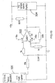
- a Hall effect current transducer 103 can be employed to measure the current flowing in the field winding 102 and an analogue differentiation circuit employing a simple CR (112 and 113) circuit as shown in Figures 9a and 9b can be used.
- rectified dc current from an ac power supply 100 is supplied via rectifier bridge 101 to the field winding 102, which is connected in series with a Hall effect current transducer 103.
- a pair of armature windings 104, 105 in a closely coupled bifilar winding are selectively connected in series with the field winding 102 by means of respective transistor switches 106, 107.
- Each of the switches 106, 107 is provided with a diode 108 to conduct current induced in the winding 104, 105 when the switch 107, 106 controlling the other winding 105, 104 is switched off.
- a snubber circuit 109 comprising a resistor 110, capacitor 111 and two diodes 111a prevents voltages induced in the windings 104, 105 from damaging the switches during the switching transition.
- the role of the snubber circuit 109 is to absorb energy associated with the leakage inductance of the closely coupled armature windings. The operation of the snubber circuit 109 is described in more detail in WO98/05112 .
- sufficient information to control the motor can be obtained from the detection of the polarity of the gradient of the field current without extraction of the signal representing the superimposed gradient of the field current. More specifically sufficient information to control the motor can be obtained from the detection of a reversal in the polarity of the gradient of the field current which is not caused by a change in state of the switches in the power electronic converter.
- the use of a comparator 114 set up to compare the differentiated field current signal to a zero level will produce a logic high or a logic low, dependent only on the polarity of the gradient of the field current.
- These logic signals can be used directly as an input to a digital controller implemented, for example, in a microcontroller 115. This is also shown in Figure 9b .
- the output voltage of Hall effect current transducer 103 developed across resistor 116 is proportional to the magnitude of the current flowing in the field winding 102, and is input to a differentiating circuit including a resistor 112 and a capacitor 113, the output of which (representing the rate of change of current in the field winding 102) is input to a comparator 114.
- the output signal from comparator 114 indicating whether the rate of change of current in the field winding 102 is positive or negative, is input to a controller 115 which controls the operation of switches 106, 107.
- a preferred embodiment of the invention achieves the differentiation of the winding current in a single step by monitoring the voltage induced in a coil, coupled to the magnetic field surrounding a conductor carrying the current in a winding of the machine.
- a conductor carrying the field current of the machine has a magnetic field surrounding it which is proportional to the current flowing in the conductor.
- a coil (or single turn) is arranged to couple with the magnetic field surrounding the conductor and will have a voltage induced in the coil which is proportional to the rate of change of the current in the conductor.
- the field around the conductor can be usefully enhanced by arranging for the field of the conductor to link the coil with a suitable magnetic path of relative permeability greater than one.
- a preferred arrangement would employ a simple magnetic core and coil with the conductor carrying the current to be differentiated passing through the centre of the core as shown in Figure 11a .
- the conductor and the coil could be on the surface of a printed circuit board as shown in Figure 11b .
- the magnetic coupling of such an arrangement can be enhanced, if necessary, by the addition of magnetic material above and below the printed circuit board.
- the voltage induced in the coil in Figure 11a or 11b is applied directly to the positive and negative signal inputs of a voltage comparator.
- the electrical output signal from the comparator will be logic high or logic low depending on the sign of the gradient of the current in the conductor passing through the coil.
- the electrical output signal of the comparator contains the information about the rotational position of the rotor and can be used as an input to a digital controller according to the invention.
- a conductor carrying the field current passes through the middle of a toroidal core 320 with a 1000 turn coil. (Telcon core HES 25VT).
- the voltage on the coil is directly proportional to the rate of change of flux in the core and hence the rate of change of field current.
- One end of the coil is fed via a 10k resistor 321 directly to the first input of a comparator 322 with no analogue processing necessary.
- the second end of the coil is connected to the second input of the comparator 322 and which, in this case, is also the zero voltage supply rail.
- the output of the comparator 322 is used as an input to a microcontroller 324 containing motor control algorithms and logic to decode the rotational position of the rotor from the electrical output signal of the comparator.
- the microcontroller is arranged to record the state of the comparator at predetermined sample points as described earlier and determine the point at which two successive samples change state. A prediction of the ideal point for reversal of the armature excitation can then be made based on the rotor speed and the time taken for the rotor to rotate a further half a stator pole pitch. Further control algorithms will be described in greater detail below.
- This embodiment of the invention requires no measurement and conditioning of the actual field current which makes it extremely low cost and very stable against changes in motor parameters due to manufacturing variations or temperature.
- the second end of the coil may be connected to any chosen reference voltage or simply connected to only the comparator.
- Figure 14 shows the sequence of events over a typical armature conduction cycle.
- the signal ARMSW1 is high. This indicates that S 1 in Figure 7a and b , is on (or switches S 1 and S 3 in Figure 6a or 6b ) and a positive voltage is applied to the armature winding and the effective (combined) armature current is positive.
- the application of a positive voltage to the armature winding induces a voltage within the field winding of the motor. As the motor rotates that mutually induced voltage changes from positive to negative causing the superimposed gradient of the field current to change from positive to negative.
- T a T pulse -T c , where T pulse is the duration of the pulse which may be calculated according to PCT/GB00/03197 or any equivalent means or may be a fixed percentage of the armature repetition cycle.
- T a T half-cycle -T pulse .
- the opposite armature switch signal ARMSW2
- ARMSW2 is taken to high to turn on the opposite armature switch(es) and apply negative voltage to the armature windings and create the negative armature current necessary for a complete cycle of operation of the motor.
- the comparator describing the sign of the gradient of the field current can be monitored during Region B.
- the voltage applied to the armature is negative. Since Region B is occurring in the latter part of an armature conduction half cycle, the gradient of the field current will be positive after the switch(es) are turned off and the comparator signal will be low.
- a change in the sign of the gradient from positive to negative indicates that the rotor has turned through a sufficient angle to have reached a point where a negative applied armature voltage is producing a negative gradient of field current.
- the armature circuit could be energised again with the opposite polarity of current. Detection of the change in gradient from positive to negative (low high in the comparator in Figure 14 ) during the time when the switch is off can therefore be used to synchronise the point of beginning the armature conduction of the opposite polarity. It will not always be necessary to begin the armature conduction of the opposite polarity immediately on detecting this transition.
- T pulse is small relative to the expected time for each half cycle, T half-cycle , then a delay can be inserted as shown in Figure 14 . If T pulse is large relative to the expected time for each half cycle, T half-cycle as occurs under full load conditions, the delay at this point will be minimal.
- FIG 14 Also shown in Figure 14 is a signal called filter locations. It is advisable that for a period of time after a switch is turned on that the comparator signal is not monitored as spurious transitions in the differentiated signal can occur after switching. Similar filtering can be applied after turn off of the switch (start of region B).
- This signal, Sstate in Figure 14 is identical to the signal normally present in a machine with a conventional sensor.
- the speed of the motor is available to the controller and is derived by the summation of the times of region A, B and C.
- a closed loop speed control system can easily be implemented by comparing this time to a target time for each half cycle and producing a larger or smaller pulse during the next half cycle to correct any error in the measured speed.
- the voltage across the power electronic circuits will vary in the profile of a rectified sine wave.
- the current profile in the armature and field windings will vary to follow this rectified sine wave.
- the mutually induced voltage in the field winding due to the excitation of the armature windings creates additional changes in the gradient of the field current superimposed on this average positive value of the gradient of the field current.
- the mutually induced electrical signal representative of the rotational position of the rotor is still present but may be masked by the longer term average of the gradient of the field current such that the gradient of the field current does not change polarity at all during an armature conduction cycle. Therefore to allow the mutually induced electrical signal representative of the rotational position of the rotor to be clearly detected, the effect of the long term average of the gradient of the current need to be removed from the differential of the current waveform.
- the differentiated signal derived from the field winding current contains the mutually induced electrical signal representative of the rotational position of the rotor but also contains any variations in the average excitation level of the machine.
- the variations in the average excitation level of the machine will usually be at a low frequency relative to the variation in the mutual inductance.
- a first method would be to filter the signal representing the differentiated field current before it is applied to the comparator. Such a filter would be a high pass or band pass filter to allow to signal containing the mutual induced electrical signal to pass while removing the signal due to the slower variation in the average excitation of the machine.
- the output of the filter can then be passed to a comparator as before and compared with zero to determine if the mutually induced electrical signal was positive or negative and hence to determine the rotational position of the rotor.
- a second method would use a low pass filter of the electrical signal which would produce a signal representing the component of the gradient of the field current which is representative of the rate of change of the average excitation of the motor. This signal is applied to the reference pin of the comparator. The electrical signal containing the mutually induced electrical signal representative of the rotational position of the rotor and the variation in the average excitation level of the machine is then compared to this non zero reference.
- This method is particularly beneficial when operating the machine from a dc voltage which is derived from rectification of an ac supply with minimal voltage smoothing.
- Figure 26 One complete implementation of the invention is illustrated by Figure 26 .
- An electrical machine with stator 30 and rotor 31 has a field windings F and armature windings A energized by a suitable power electronic controller 401.
- a controller 400 sends signals to the power electronic controller 401 to control the armature current to achieve the desired operation of the machine.
- the armature windings A When the machine is operating as a motor, the armature windings A will be supplied with electrical current from the power electronic controller by the application of applied voltage in synchronism with the rotation of the rotor 31.
- a mutually induced first electrical signal dependent on rotational position of the rotor will be induced within the field windings F. This will create a superimposed gradient in the field current delivered by the power electronic controller 401.
- the mutually induced first electrical signal can be extracted from the field current by block 402 which may be a differentiator circuit or may be a coil coupled to the magnetic field around the field current conductor.
- the output of 402 represents the magnitude of the mutually induced first electrical signal.
- Block 403 is an optional signal conditioning circuit which may contain a filter circuit.
- Block 404 creates a reference voltage for the comparator 405.
- the reference voltage can be zero such that the comparator 405 determines the polarity of the mutually induced first electrical signal.
- the output from the comparator is a digital signal indicating if the mutually induced first electrical signal is less than or greater than the threshold applied by block 404.
- This comparator output, a second electrical signal represents the rotational position of the rotor relative to the stator and is supplied to the controller 400 to maintain synchronism between the armature excitation and the rotor position.
- the controller 400 may be a microcontroller or an application specific integrated circuit or any other appropriate electronic circuit.
- block 404 implements a low pass filter to create the reference from an average value of the mutually induced first electrical signal. This is applied to one input of the comparator. In this case block 403 may pass the mutually induced first electrical signal directly to the comparator without any filtering.
- a new procedure incorporating a further embodiment of the invention allows successful starting of the motor.
- position information can be found by pulsing one winding of the motor e.g. the armature winding.
- the voltage induced in the other winding e.g. the field winding creates a variation in the current flowing in the second winding which can be detected to obtain some information about rotor position.
- Figure 15 shows the position information available from this method. If S 1 (and S 3 if a full bridge inverter) is turned on for a short period of time, a positive voltage will be applied to the armature winding. The current in the armature winding will increase. However, the current in the field winding will increase or decrease depending on the orientation of the rotor and the degree of magnetic coupling between the armature and the field winding.
- Figure 15 shows two positions a stator pole pitch apart (45° in the 8/4 motor) where the poles of the rotor are aligned with stator poles.
- Aligned Position 1 is the position of stable equilibrium for the rotor when the current in the field winding and the armature winding are both positive (aligned position with S 1 energised (and S 3 if present)).
- Aligned Position 2 is the position of stable equilibrium for the rotor when the current in the field winding is positive but the current in the armature winding is negative (aligned position with S 2 energised (and S 4 if present)).
- Aligned Position 1 applies a short pulse to S 1 applies a positive voltage to the armature and produces a negative gradient in the field current. In the configuration used in the earlier description of the comparator this will produce a high value in the comparator. In this same region pulsing S 2 will produce a positive increase in the field current and a low value of comparator as shown in Figure 15 .
- the initial pulse is of a duration sufficient to establish the field current. Detection of the field current and its gradient during the initial pulse is difficult because the effect of the voltage induced from the armature into the field is masked by the large positive rate of change of current associated with the initialisation of field current.
- the appropriate length of time for the change in excitation to occur from the initial polarity determined by the initial region selection to the polarity required for torque production in a known direction will depend on lamination design, static load torque, rotor inertia, supply voltage, pwm duty ratio, stator winding impedances etc. This time can be optimized empirically or determined from a mathematical model of the electrical and mechanical system.
- stator asymmetry in the flux switching motor may make one region slightly wider than the other region but does not affect the principle of the invention.
- the method can be easily adapted to provide rotation in a direction opposite to the direction for which the asymmetry has been designed by moving the rotor initially in the known starting direction and then initiating a reversal of direction.
- trace X 10 is a mechanical sensor on the shaft of the motor shown for reference only
- trace X 12 is the combined armature current (20A/div)
- trace X 14 is the electrical output signal from a comparator produced by comparing the differentiated field current signal to a zero reference
- trace X 16 is the field current (20A/div).
- the comparator rising edge is not present during the on time of the switches in the first and third armature current pulse after the end of the pwm chopping.
- An embodiment of the invention allows for the selection of switching times for the positive and negative cycles of the armature to be pre-calculated from the knowledge of the rotor position and speed just prior to the transition from pwm to single pulse mode.
- Driving the motor in an apparently open loop manner for a number of armature pulses gives the field current transition time to settle out and normal comparator single pulse operation (as in Figure 14 ) to be restored. This transition is shown in Figure 16 .
- a further embodiment of the invention can be employed.
- the position of the start and finish of the application of voltage to the winding with respect to rotor position can be altered by monitoring the relative time periods of positive and/or negative gradient of a winding current during any part of the machine rotation.
- the fourth pulse after the transition is monitored to implement an adaptive pulse position algorithm.
- the time from the turn on of a switch to initiate the fourth armature conduction block after the transition from pwm to the rising edge of the comparator gives a measure of the position of the pulse. This time is shown by the cursors in Figure 17(a)
- trace X 20 is a mechanical sensor on the shaft of the motor shown for reference only
- trace X 22 is the combined armature current (20A/div)
- trace X 24 is the electrical output signal from a comparator produced by comparing the differentiated field current signal to a zero reference
- trace X 26 is the field current (20A/div).
- Traces X 29 , X 30 , X 32 , X 34 are detailed views of X 20 , X 22 , X 24 , X 26 expanded in the horizontal axis for clearer viewing of the fourth armature current pulse after entering single pulse operation.
- the period of a complete cycle of armature excitation in a motor with 8 stator teeth and 4 rotor teeth (positive and negative armature conduction blocks) is 3 ms at this speed.
- One example of this embodiment of the invention measures the time from the application of positive voltage to the armature to the rising edge of the comparator (the point at which the gradient of the field current changes from positive to negative). This time is the time defined as T c in Figure 14 .
- T c T c .
- T c The value quoted in this example of 750 ⁇ s corresponds to approximately one half of the armature conduction block. It is preferable therefore to make adjustments to the pulse ensure that the value of T c is less than 50% of the duration of an armature half cycle and preferably T c should be in the range 20%-40% of the armature half cycle. However if the time of the armature voltage pulse (T pulse ) is less than 50% of T half-cycle , the value of T c may preferably be allowed to be lower than 20% of T half-cycle .
- the turn on point of the armature switches may be earlier or later than ideal.
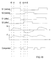
- the non-ideal turn on point of the armature current can be detected from the length of time, T c , taken from the turn on of the switch to the peak of the field current trace. This is shown in Figure 18 as the time t 0 to t 1 and was defined in Figure 14 as T c .
- T c will become a smaller proportion of T pulse
- T pulse is the time during which positive or negative voltage is applied to the armature during an armature conduction block (t 2 -t 0 in Figure 18 ).
- This time can be measured by an appropriate electronic circuit or by a timer in a microcontroller.
- the measured value of t 1 - t 0 can be used to calculate a better position for the next armature excitation pulse such that the excitation of S 2 is initiated at t 3 rather than at t 4 .
- the earlier turn on point moves the armature conduction block closer to the ideal torque producing region.
- Figure 19 shows the implementation of this algorithm to correct armature excitation pulses which were occurring earlier than is ideal.
- trace X 60 is a mechanical sensor on the shaft of the motor shown for reference only
- trace X 62 is the combined armature current (20A/div);
- trace X 64 is a digital output of the microcontroller showing the location of timer interrupts initiating the start of each armature conduction pulse;
- trace X 66 is the electrical output signal from a comparator produced by comparing the differentated field current signal to a zero reference. Two positive and two negative armature pulses which have been positioned by timers in the absence of a comparator rising edge during the off time between armature pulses.
- T c is measured (just past the middle of the zoom window in Figure 19 ).
- T b is then calculated as 1.25 T c which repositions the next armature current pulse, reducing the current drawn and immediately re-establishes the comparator edge during the off time.
- the repositioning algorithms described so far employ pre-calculated adjustments to the pulse position to ensure that the position of the pulse is moved to a position such that the comparator signal during the off time of the switches is allowed to re-occur.
- the off-time comparator signal may not occur frequently enough to be relied upon for synchronisation of the pulse position. This may occur in the following circumstances:
- the re-positioning algorithms described so far also employ specific timings to shift the position of the pulse. These timings are not generally applicable across the speed range of the machine and are therefore limited to specific speeds.
- An improved embodiment of the invention allows pulse repositioning to occur continually to adjust the position of the armature pulse in every operating cycle for optimal synchronisation with the rotor position.
- This further embodiment uses the fact that for the best torque production the position of the armature excitation pulse relative to the rotor position should be continually adjusted so that the time T c , from the turn on of an armature switch to the turning point of the field current should be maintained in the range 15% to 65% of T pulse and preferably in the range 25% to 55% of T pulse . This can be achieved by measurement of T c and then calculating the value of the next T b to adjust the start position of the next pulse to be earlier or later than the measured pulse.
- the turning point of the field current should occur x%, which may be between 25% and 65%, and is more preferably between 35% and 55% of the way through each respective armature switch on time.
- the first armature pulse is associated with negative armature current and is controlled by the signal ARMSW2 energising S 2 (and S 4 if a full bridge inverter).
- the length of the first armature pulse is Tpulse1, where Tpulse1 is calculated as the length required to maintain the desired speed or deliver the required torque at the current speed.
- Tpulse1 the signal ARMSW2 goes low for a time Tb1, de-energising the armature winding.
- Tb1 was calculated as will be described below for Tb2.
- ARMSW1 goes high, initiating the energisation of the armature with positive current.
- the time taken from the point of turning on an armature switch to the turning point of the field current is measured by the microcontroller or other appropriate circuit.
- the target value of x % of the present armature pulse duration is compared to the target value of x % of the present armature pulse duration.
- the target value for the length of Region C is shown on the diagram as the dashed line just after the actual occurrence of the turning point of the field current.
- the measured value Tc2 is less than the target value.
- this error is a negative number since Tc2 was less than the target value.
- the fact that this error is a negative number indicates that the pulse position relative to rotor position was too late for optimal torque production.
- the error is used to adjust the value of the next off time, Tb2, to deliver a pulse of more optimal position relative to rotor position.
- the error signal is used in a PID controller to modify the duration of the off time between armature pulses so that the position of the next armature pulse is closer to the target value.
- T b 2 Calculated T b before correction + K P error
- T b 2 T a 1 + T b 1 + T c 1 ⁇ T pulse 2 + K P error
- K P is the proportional gain in a proportional control loop. Its value controls the rate at which the system will converge on a stable solution. If K P is too high instability may result. A value in the region of unity will usually be acceptable for typical applications.
- the controller may be further improved by using the integral and derivative of the error as will be known to those skilled in the art.
- Fig. 24 shows that the length of Tb2 is shorter than Tb1 due to the negative sign of the error. The position of Tpulse3 is therefore brought forward relative to rotor position and the value of Tc3 is then close to the target value for Tc.
- Tb During the calculation of each Tb following the measurement of Tc it is also important to recalculate the current time for an electrical half cycle of the motor, T half-cycle , as this allows the speed of the machine to be accurately monitored at all times. This ensures that the length of the next pulse and its target value for Tc are up to date with the present speed of the motor.
- the positive error value is added to the calculated value of T b to create a new value of New T b which is used to push back the start of the next armature pulse by 1 ⁇ s.
- the slightly later turn on point in the next cycle will act to shorten the value of T c which will be measured in the next cycle and help to maintain the pulse in the correct position.
- the embodiment can be implemented with any pulse size, at any rotor speed and with any target percentage for the time corresponding to T c . In practice it may be advantageous to adjust the target percentage of the pulse with load to maintain optimum efficiency.
- the pulse repositioning algorithms can also be used when the motor is operating in pulse width modulation mode.
- the time Tc is measured by sampling the state of the comparator in each PWM cycle to detect when the state of the comparator changes from the state in the previous pwm cycle.
- the error calculation and the adjustment of the time Tb between the pulses proceeds as in single pulse mode.
- the field magnet means being constituted by field windings
- the field magnet means may be a field winding or a permanent magnet.
- a flux switching machine in which the field magnet means is a permanent magnet is shown in Figure 25 .
- Four permanent magnets 354 intersperse 4 steel sections 350.
- the armature windings would be inserted in the slots in the steel sections 350, each armature winding spanning two stator teeth as in Figure 4 .
- the rotor 352 is similar in form to the rotor of Figure 4 .
- Implementation of the invention to produce a position sensing means requires the insertion of an additional electrical winding arranged to have an axis transverse to the axis of an armature winding.
- the smaller slots 356 adjacent to the permanent magnet sections can be used to carry this additional electrical winding.
- the additional winding will also have a pitch corresponding to two stator teeth.
- the additional electrical winding would normally be arranged to couple the flux passing through the permanent magnet section of the stator. As an alternative this can be achieved by placing a small winding co-axial with at least one permanent magnet section of the motor.
- the methods can proceed as previously described. Furthermore an additional electrical winding closely coupled to the field winding can be provided in a flux switching motor which will produce a mutually induced voltage dependent on rotational position of the rotor in a manner similar to the methods already described.
- FIG. 21 One complete embodiment of the invention is shown in the circuit of Figure 21 , in which parts common to the embodiment of Figure 12 are denoted by like reference numerals and parts common to the embodiment of Figure 9a are denoted by like reference numerals but increased by 200, and some experimental results obtained from a motor controlled according to the invention is shown in Figure 22 and 23 in which Figure 22 shows results at 1.0 Nm and 1.8 Nm respectively. Whilst Figure 21 shows the implementation of the inverter configuration of Figure 7(a) the invention can be equally implemented with the circuits of Figures 7b , 6a and 6b .
- Trace X 90 is the electrical output signal from the comparator Trace X 92 is the armature current 10A/div Trace X 94 mechanical sensor signal (for reference only) 5V/div Trace X 96 timer signals 5V/div Trace X 100 is the electrical output signal from the comparator Trace X 102 is the armature current 10A/div Trace X 104 mechanical sensor signal (for reference only) 5V/div Trace X 106 timer signals 5V/div
- the sign and magnitude of the rate of change of current in said winding is recorded rather than just the polarity of the sign.
- the recorded value can be compared to the known (or pre-determined) variation in rate of change of current with position (taking into account rotor speed and current magnitudes). The result of such a comparison would provide data about the position of the rotor in between the positions where the gradient of the said currents changes polarity.
- Such a system would be more reactive to changes in rotor speed within each armature conduction cycle but would also require more expensive circuitry and would be prone to variations in motor parameters due to temperature and mechanical tolerance.
Landscapes
- Engineering & Computer Science (AREA)
- Power Engineering (AREA)
- Control Of Motors That Do Not Use Commutators (AREA)
- Control Of Electric Motors In General (AREA)
Claims (39)
- Geschalteter Reluktanzmotor, umfassend:einen Rotor (7) mit einer Vielzahl von Rotorpolen;einen Stator (2), der den Rotor (7) drehbar aufnimmt, und wobei der Stator (2) mindestens eine Feldwicklung (202), die eine erste magnetomotorische Kraft zwischen dem Rotor (7) und dem Stator (2) erzeugt, und mindestens eine Ankerwicklung (204) aufweist, die dafür eingerichtet ist, elektrischen Strom zu tragen, der synchron mit der Rotation des Rotors (7) in Bezug auf den Stator (2) variiert, um eine variierende zweite magnetomotorische Kraft mit einer Komponente quer zur ersten magnetomotorischen Kraft zu erzeugen, während die erste magnetomotorische Kraft erzeugt wird; undein Steuerungsmittel (115), welches die Zufuhr von elektrischem Strom zu der oder jeder Ankerwicklung (204) steuert;dadurch gekennzeichnet, dass der geschaltete Reluktanzmotor ein Positionserfassungsmittel (103) umfasst, das mindestens ein induziertes erstes elektrisches Signal ermittelt, das von der Rotationsposition des Rotors in Bezug auf den Stator abhängt, wobei das oder jedes erste elektrische Signal in mindestens einer Feld- oder Ankerwicklung (202, 204) durch eine Spannung über mindestens einer jeweiligen Anker- oder Feldwicklung (202, 204) induziert wird, wobei die Spannung ein Erfordernis für den normalen Betrieb des geschalteten Reluktanzmotors ist, um die Anker- oder Feldwicklung (204, 202) zu erregen, um elektrische Energie in mechanische Energie umzuwandeln, um dadurch dem Steuerungsmittel (103) mindestens ein zweites elektrisches Signal zuzuführen, das die Rotationsposition des Rotors in Bezug auf den Stator darstellt, um die Zufuhr von elektrischem Strom zu der oder jeder Ankerwicklung (204) zu steuern.
- Geschalteter Reluktanzmotor nach Anspruch 1, worin der Stator (2) eine Vielzahl von Statorpolen (31) aufweist, und mindestens eine Ankerwicklung (204) mit einer Teilung gewickelt ist, die einer Vielzahl von Statorpolteilungen entspricht.
- Geschalteter Reluktanzmotor nach Anspruch 1 oder 2, worin mindestens eine Feldwicklung (202) geeignet ist, in Reihe oder parallel zu einer Schaltung geschaltet zu werden, die mindestens eine Ankerwicklung (204) enthält.
- Geschalteter Reluktanzmotor nach Anspruch 3, worin das Positionserfassungsmittel (103) dafür eingerichtet ist, das mindestens eine induzierte erste elektrische Signal in der mindestens einen Feldwicklung (202) zu ermitteln.
- Geschalteter Reluktanzmotor nach einem der vorhergehenden Ansprüche, worin das Positionserfassungsmittel (103) dafür eingerichtet ist, zu ermitteln, wann mindestens ein induziertes erstes elektrisches Signal mindestens einen Schwellenwert durchläuft, um das mindestens eine zweite elektrische Signal zu erzeugen.
- Geschalteter Reluktanzmotor nach Anspruch 5, worin das Positionserfassungsmittel (103) dafür eingerichtet ist, zu ermitteln, wann mindestens ein induziertes erstes elektrisches Signal mindestens einen jeweiligen Schwellenwert durchläuft, wenn mindestens eine der Wicklungen (202, 204) mit im Wesentlichen gleichmäßiger Spannung erregt wird und/oder wenn mindestens eine der Wicklungen (202, 204) nicht erregt wird, wobei die Spannung ein Erfordernis des normalen Betriebs des Motors ist, um elektrische Energie in mechanische Energie umzuwandeln.
- Geschalteter Reluktanzmotor nach Anspruch 5 oder 6, worin das Positionserfassungsmittel (103) dafür eingerichtet ist, zu bestimmen, wann die Erregung mindestens einer der Ankerwicklungen zu beginnen und/oder zu beenden ist, indem relative Zeitverhältnisse bestimmt werden, für die während einer vorbestimmten Rotationsperiode des Rotors (7) mindestens ein induziertes erstes elektrisches Signal größer oder kleiner als mindestens ein jeweiliger Schwellenwert in mindestens einer der Wicklungen (202, 204) ist.
- Geschalteter Reluktanzmotor nach Anspruch 7, worin das Positionserfassungsmittel (103) dafür eingerichtet ist, die Zeitgebung der Erregung mindestens einer der Ankerwicklungen (204) zu steuern, um relative Zeitverhältnisse aufrechtzuerhalten, für die das mindestens eine induzierte erste elektrische Signal innerhalb vorbestimmter Grenzen größer oder kleiner als mindestens ein jeweiliger Schwellenwert in mindestens einer der Wicklungen (202, 204) ist.
- Geschalteter Reluktanzmotor nach Anspruch 8, worin die vorbestimmten Grenzen dafür eingerichtet sind, in Abhängigkeit von der Ausgangsleistung des geschalteten Reluktanzmotors zu variieren.
- Geschalteter Reluktanzmotor nach Anspruch 8 oder 9, worin das Positionserfassungsmittel (103) dafür eingerichtet ist, die Zeitgebung der Erregung mittels mindestens eines in das Steuerungsmittel eingegebenen Fehlersignals zu steuern.
- Geschalteter Reluktanzmotor nach einem der Ansprüche 8 bis 10, worin das Positionserfassungsmittel (103) dafür eingerichtet ist, die Zeitgebung der Erregung selektiv zu steuern, und zwar als Reaktion darauf, dass es nicht gelingt zu ermitteln, dass mindestens ein induziertes erstes elektrisches Signal während einer vorbestimmten Zeitspanne einen Schwellenwert durchläuft.
- Geschalteter Reluktanzmotor nach einem der Ansprüche 5 bis 11, worin das Positionserfassungsmittel (103) dafür eingerichtet ist, zu ermitteln, wann mindestens ein induziertes erstes elektrisches Signal mindestens einen jeweiligen Schwellenwert durchläuft, um mindestens ein zweites elektrisches Signal zu erzeugen, wobei der mindestens eine Schwellenwert eine Funktion des entsprechenden induzierten ersten elektrischen Signals ist.
- Geschalteter Reluktanzmotor nach einem der vorhergehenden Ansprüche, worin das Positionserfassungsmittel (103) dafür eingerichtet ist, mindestens ein induziertes erstes elektrisches Signal, das von der Rotationsposition des Rotors in Bezug auf den Stator abhängig ist, aus der Änderungsrate des in einer elektrischen Wicklung der Maschine auftretenden Stroms zu extrahieren, der als Folge des Vorhandenseins einer Spannung über mindestens einer der Wicklungen entsteht.
- Geschalteter Reluktanzmotor nach Anspruch 13, worin das Positionserfassungsmittel (103) mindestens eine jeweilige Spule einschließt, die dafür eingerichtet ist, magnetisch mit einem Magnetfeld gekoppelt zu werden, das durch einen Leiter erzeugt wird, der Strom führt, welcher mindestens eine der Wicklungen durchläuft.
- Geschalteter Reluktanzmotor nach einem der vorhergehenden Ansprüche, worin das Positionserfassungsmittel (103) dafür eingerichtet ist, Daten zu erlangen, die sich auf mindestens ein induziertes erstes elektrisches Signal beziehen, und die Daten mit Daten zu vergleichen, die sich auf mindestens eine bekannte Rotorposition beziehen.
- Geschalteter Reluktanzmotor nach einem der vorhergehenden Ansprüche, worin das Positionserfassungsmittel (103) dafür eingerichtet ist, mindestens ein zweites elektrisches Signal bereitzustellen, das die Rotationsposition des Rotors (7) im Stillstand darstellt, indem mindestens ein induziertes erstes elektrisches Signal in mindestens einer der Wicklungen (202, 204) bestimmt wird, wenn mindestens eine andere der Wicklungen (202, 204) erregt wird.
- Geschalteter Reluktanzmotor nach Anspruch 16, worin das Steuerungsmittel dafür eingerichtet ist, zu bewirken, dass der Rotor (7) sich als Reaktion auf mindestens ein zweites elektrisches Signal von dem Positionserfassungsmittel, das beim Stillstand des Rotors (7) erzeugt wird, in eine Position stabilen Gleichgewichts in Bezug auf den Stator (2) bewegt.
- Geschalteter Reluktanzmotor nach Anspruch 17, worin das Positionserfassungsmittel (103) dafür eingerichtet ist, die nächstgelegene Position des stabilen Gleichgewichts des Rotors (7) in Bezug auf den Stator (2) anzugeben, indem das jeweilige induzierte erste elektrische Signal in der mindestens einen Wicklung beobachtet wird, wenn die mindestens eine andere Wicklung erregt wird.
- Geschalteter Reluktanzmotor nach einem der vorhergehenden Ansprüche, worin das Positionserfassungsmittel dafür eingerichtet ist, mindestens ein induziertes erstes elektrisches Signal durch intermittierendes Abtasten des Signals zu überwachen.
- Geschalteter Reluktanzmotor nach einem der vorhergehenden Ansprüche, worin das Positionserfassungsmittel (103) dafür eingerichtet ist, mindestens ein zweites elektrisches Signal durch intermittierendes Abtasten des Signals zu überwachen.
- Geschalteter Reluktanzmotor nach einem der vorhergehenden Ansprüche, worin das Positionserfassungsmittel (103) dafür eingerichtet ist, die Änderungsrate des mindestens einen induzierten ersten elektrischen Signals zu ermitteln, die durch eine Änderung des Magnetflusses durch die Wicklung (202, 204) verursacht wird.
- Verfahren zum Steuern eines geschalteten Reluktanzmotors, wobei der Motor einen Rotor (7) mit einer Vielzahl von Rotorpolen und einen Stator (2) zum drehbaren Aufnehmen des Rotors (7) umfasst und der Stator (2) mindestens eine Feldwicklung (202) zum Erzeugen einer ersten magnetomotorischen Kraft zwischen dem Rotor und dem Stator aufweist, und wobei der Stator (2) mindestens eine Ankerwicklung (204) aufweist, die dafür eingerichtet ist, elektrischen Strom zu tragen, der synchron mit der Rotation des Rotors (7) in Bezug auf den Stator (2) variiert, um eine variierende zweite magnetomotorische Kraft mit einer Komponente quer zur ersten magnetomotorischen Kraft zu erzeugen, während die erste magnetomotorische Kraft erzeugt wird, wobei das Verfahren durch die folgenden Schritte gekennzeichnet ist:Ermitteln mindestens eines induzierten ersten elektrischen Signals, das von der Rotationsposition des Rotors (7) in Bezug auf den Stator (2) abhängt, wobei das oder jedes erste elektrische Signal in mindestens einer der Feld- oder Ankerwicklungen (202, 204) durch eine Spannung über mindestens einer jeweiligen Ankerwicklung oder Feldwicklung induziert wird, wobei die Spannung ein Erfordernis des normalen Betriebs des Motors ist, um die Ankerwicklung oder Feldwicklung (204, 202) zu erregen, um elektrische Energie in mechanische Energie umzuwandeln;Zuführen mindestens eines zweiten elektrischen Signals, das die Rotationsposition des Rotors (7) in Bezug auf den Stator (2) darstellt; undSteuern der Zufuhr von elektrischem Strom zu der oder jeder der Ankerwicklungen (204) als Reaktion auf mindestens ein zweites elektrisches Signal.
- Verfahren nach Anspruch 22, worin die Ermittlung des mindestens einen induzierten ersten elektrischen Signals umfasst: Ermitteln mindestens eines induzierten ersten elektrischen Signals in mindestens einer Feldwicklung (202).
- Verfahren nach Anspruch 22 oder 23, worin die Ermittlung des mindestens einen induzierten ersten elektrischen Signals umfasst: Ermitteln, wann mindestens ein induziertes erstes elektrisches Signal mindestens einen Schwellenwert durchläuft, um mindestens ein zweites elektrisches Signal zu erzeugen.
- Verfahren nach Anspruch 24, worin die Ermittlung des mindestens einen induzierten ersten elektrischen Signals umfasst: Ermitteln, wann mindestens ein induziertes erstes elektrisches Signal mindestens einen jeweiligen Schwellenwert durchläuft, wenn mindestens eine der Wicklungen (202, 204) mit einer im Wesentlichen gleichmäßigen Spannung erregt wird und/oder wenn mindestens eine der Wicklungen (202, 204) nicht erregt wird, wobei die Spannung ein Erfordernis des normalen Betriebs des Motors ist, um elektrischer Energie in mechanische Energie umzuwandeln.
- Verfahren nach Anspruch 24 oder 25, ferner den Schritt umfassend: Bestimmen, wann die Erregung mindestens einer der Ankerwicklungen (204) zu beginnen und/oder zu beenden ist, indem relative Zeitverhältnisse bestimmt werden, für die während einer vorbestimmten Rotationsperiode des Rotors (7) mindestens ein induziertes erstes elektrisches Signal größer oder kleiner als mindestens ein jeweiliger Schwellenwert in mindestens einer der Wicklungen (202, 204) ist.
- Verfahren nach Anspruch 26, ferner den Schritt umfassend: Steuern der Zeitgebung der Erregung von mindestens einer der Ankerwicklungen (204), um relative Zeitverhältnisse aufrechtzuerhalten, für die mindestens ein induziertes erstes elektrisches Signal innerhalb vorbestimmter Grenzen größer oder kleiner als mindestens ein jeweiliger Schwellenwert in mindestens einer der Wicklungen (202, 204) ist.
- Verfahren nach Anspruch 27, ferner den Schritt umfassend: Verändern der vorbestimmten Grenzen in Abhängigkeit von der Ausgangsleistung des geschalteten Reluktanzmotors.
- Verfahren nach einem der Ansprüche 22 bis 28, ferner den Schritt umfassend: Steuern der Zeitgebung der Erregung mittels mindestens eines Fehlersignals.
- Verfahren nach Anspruch 29, ferner den Schritt umfassend: selektives Steuern der Zeitgebung der Erregung als Reaktion darauf, dass es nicht gelingt zu ermitteln, dass mindestens ein induziertes erstes elektrisches Signal während einer vorbestimmten Zeitspanne einen Schwellenwert durchläuft.
- Verfahren nach einem der Ansprüche 22 bis 30, worin die Ermittlung des mindestens einen induzierten ersten elektrischen Signals umfasst: Ermitteln, wann mindestens ein induziertes erstes elektrisches Signal mindestens einen jeweiligen Schwellenwert durchläuft, um mindestens ein zweites elektrisches Signal zu erzeugen, wobei mindestens ein Schwellenwert eine Funktion eines Durchschnittswerts des entsprechenden induzierten ersten elektrischen Signals ist.
- Verfahren nach einem der Ansprüche 22 bis 31, ferner den Schritt umfassend: Extrahieren mindestens eines induzierten ersten elektrischen Signals, das von der Rotationsposition des Rotors (7) in Bezug auf den Stator (2) abhängig ist, aus der Änderungsrate des Stroms, der in einer der Wicklungen (202, 204) auftritt, die als Folge des Vorhandenseins einer Spannung über einer oder mehreren anderen der Wicklungen (202, 204) entsteht.
- Verfahren nach einem der Ansprüche 22 bis 32, ferner den Schritt umfassend: Erlangen von Daten, die sich auf mindestens ein induziertes erstes elektrisches Signal beziehen, und Vergleichen der Daten mit Daten, die sich auf mindestens eine bekannte Rotorposition beziehen.
- Verfahren nach einem der Ansprüche 22 bis 33, ferner den Schritt umfassend: Bereitstellen mindestens eines zweiten elektrischen Signals, das die Rotationsposition des Rotors (7) im Stillstand darstellt, indem mindestens ein induziertes erstes elektrisches Signal in mindestens einer der Wicklungen (202, 204) bestimmt wird, wenn mindestens eine andere der Wicklungen (202, 204) erregt wird.
- Verfahren nach Anspruch 34, ferner den Schritt umfassend: Bewirken, dass der Rotor (7) sich als Reaktion auf mindestens ein zweites elektrisches Signal von dem Positionserfassungsmittel (103), das beim Stillstand des Rotors (7) erzeugt wird, in eine Position stabilen Gleichgewichts in Bezug auf den Stator (2) bewegt.
- Verfahren nach Anspruch 35, ferner den Schritt umfassend: Angeben der nächstgelegenen Position des stabilen Gleichgewichts des Rotors (7) in Bezug auf den Stator (2), indem das jeweilige induzierte erste elektrische Signal in der mindestens einen der Wicklungen (202, 204) beobachtet wird, wenn mindestens eine andere der Wicklungen (202, 204) erregt wird.
- Verfahren nach einem der Ansprüche 22 bis 36, ferner den Schritt umfassend: Überwachen mindestens eines induzierten ersten elektrischen Signals durch intermittierendes Abtasten des Signals.
- Verfahren nach einem der Ansprüche 22 bis 37, ferner den Schritt umfassend: Überwachen mindestens eines induzierten zweiten elektrischen Signals durch intermittierendes Abtasten des Signals.
- Verfahren nach einem der Ansprüche 22 bis 38, worin das Ermitteln des mindestens einen ersten elektrischen Signals abhängig von der Rotationsposition des Rotors (7) umfasst: Ermitteln der Änderungsrate des mindestens einen induzierten ersten elektrischen Signals, die durch eine Änderung des Magnetflusses durch die Wicklung (202, 204) verursacht wird.
Applications Claiming Priority (3)
| Application Number | Priority Date | Filing Date | Title |
|---|---|---|---|
| GBGB0221117.5A GB0221117D0 (en) | 2002-09-12 | 2002-09-12 | Control of electrical machines |
| GB0221117 | 2002-09-12 | ||
| PCT/GB2003/003973 WO2004025822A1 (en) | 2002-09-12 | 2003-09-12 | Control of an electrical reluctance machine |
Publications (2)
| Publication Number | Publication Date |
|---|---|
| EP1537648A1 EP1537648A1 (de) | 2005-06-08 |
| EP1537648B1 true EP1537648B1 (de) | 2019-06-05 |
Family
ID=9943896
Family Applications (1)
| Application Number | Title | Priority Date | Filing Date |
|---|---|---|---|
| EP03750914.8A Expired - Lifetime EP1537648B1 (de) | 2002-09-12 | 2003-09-12 | Reglung einer elektrischen reluktanzmaschine |
Country Status (7)
| Country | Link |
|---|---|
| US (1) | US7429840B2 (de) |
| EP (1) | EP1537648B1 (de) |
| JP (1) | JP2005538675A (de) |
| CN (1) | CN100375384C (de) |
| AU (2) | AU2003269135A1 (de) |
| GB (1) | GB0221117D0 (de) |
| WO (2) | WO2004025822A1 (de) |
Families Citing this family (52)
| Publication number | Priority date | Publication date | Assignee | Title |
|---|---|---|---|---|
| EP1596495B1 (de) * | 2004-05-12 | 2011-04-27 | ebm-papst St. Georgen GmbH & Co. KG | Verfahren zum sensorlosen Betrieb eines elektronisch kommutierten Motors, und Motor zur Durchführung eines solchen Verfahrens |
| DE102004030460B3 (de) * | 2004-06-24 | 2005-06-30 | Hans Hermann Rottmerhusen | Elektromotorischer Antrieb für ein Fahrzeug |
| JP5120586B2 (ja) * | 2005-06-28 | 2013-01-16 | 株式会社デンソー | 界磁巻線型同期機 |
| DE602005021794D1 (de) * | 2005-11-03 | 2010-07-22 | Black & Decker Inc | Steuerung geschalteter Reluktanzmaschinen |
| US7423394B2 (en) * | 2006-01-12 | 2008-09-09 | Intelasense, Llc | Single-sensor based commutation of multi-phase motor |
| US7880424B2 (en) * | 2006-09-28 | 2011-02-01 | Denso Corporation | Rotary electric apparatus having rotor with field winding inducing current therethrough for generating magnetic field |
| WO2008047959A1 (en) * | 2006-10-19 | 2008-04-24 | Lg Electronics Inc. | Switched reluctance motor |
| GB0702975D0 (en) * | 2007-02-15 | 2007-03-28 | Switched Reluctance Drives Ltd | Control of an electrical machine |
| US8125170B2 (en) * | 2007-06-16 | 2012-02-28 | Board Of Regents, The University Of Texas System | Techniques and apparatus for the measurement of mutual inductance in a switched reluctance machine |
| US7755308B2 (en) * | 2007-06-29 | 2010-07-13 | Caterpillar Inc | Conduction angle control of a switched reluctance generator |
| US7852038B2 (en) * | 2007-08-14 | 2010-12-14 | Ramu Inc. | Single switch controlled switched reluctance machine |
| GB2455123A (en) * | 2007-11-29 | 2009-06-03 | Technelec Ltd | Control of electrical machines |
| GB2455122A (en) * | 2007-11-29 | 2009-06-03 | Technelec Ltd | Control of electrical machines |
| TWI424678B (zh) * | 2008-04-14 | 2014-01-21 | Feeling Technology Corp | 切換式調整電路及雙線圈馬達裝置 |
| GB2462446A (en) * | 2008-08-07 | 2010-02-10 | Technelec Ltd | Micro-steping reluctance motor |
| EP2321888A4 (de) * | 2008-08-22 | 2017-03-15 | DRS Power & Control Technologies, Inc. | Mehrfachspannungsgenerator uns spannungsregelungsverfahren für leistungsdichte integrierte stromversorgungssysteme |
| GB2469129B (en) | 2009-04-04 | 2013-12-11 | Dyson Technology Ltd | Current controller for an electric machine |
| GB2469128A (en) * | 2009-04-04 | 2010-10-06 | Dyson Technology Ltd | Generating control signals for an electric machine from a position sensor |
| GB2469140B (en) | 2009-04-04 | 2013-12-11 | Dyson Technology Ltd | Control of an electric machine |
| GB2469133B (en) * | 2009-04-04 | 2014-04-23 | Dyson Technology Ltd | Control system for an electric machine |
| GB2469130B (en) * | 2009-04-04 | 2014-01-29 | Dyson Technology Ltd | Control system for an electric machine |
| GB0906020D0 (en) * | 2009-04-07 | 2009-05-20 | Trw Ltd | Motor drive circuitry |
| US20120086380A1 (en) * | 2010-10-04 | 2012-04-12 | Evantage Limited | Electric motor having windings operable in parallel and/or series, and related methods |
| FR2971377B1 (fr) * | 2011-02-09 | 2013-02-01 | Renault Sa | Procede et dispositif de pilotage d'une machine electrique a reluctance |
| GB2489423A (en) | 2011-03-25 | 2012-10-03 | Technelec Ltd | Flux switching electrical machine with slotted rotor |
| CN102291068B (zh) * | 2011-07-14 | 2013-04-24 | 中国矿业大学 | 四象限无位置传感器开关磁阻电机控制方法 |
| DE102011082365A1 (de) * | 2011-09-08 | 2013-03-14 | Siemens Ag | Supraleitende Maschine und Verfahren zu deren Betrieb |
| GB2501129A (en) * | 2012-04-13 | 2013-10-16 | Melexis Technologies Nv | Determining rotor position in sensorless switched reluctance motors |
| US9000699B2 (en) | 2011-11-10 | 2015-04-07 | Whirlpool Corporation | Determination of magnetic flux and temperature of permanent magnets in washing machine motor |
| US9236784B2 (en) | 2012-03-30 | 2016-01-12 | General Electric Company | Flux-switching electric machine |
| EP2728713A1 (de) * | 2012-10-31 | 2014-05-07 | Openhydro IP Limited | Elektrische Maschine |
| WO2014108746A1 (en) | 2013-01-09 | 2014-07-17 | Freescale Semiconductor, Inc. | Device for determining a position of a rotor of a polyphase electric motor |
| US9041232B2 (en) * | 2013-10-11 | 2015-05-26 | General Electric Company | Electric generator system |
| AU2016215158B2 (en) * | 2015-02-04 | 2018-04-19 | Turntide Technologies Inc. | Reliable control of high rotor pole switched reluctance machine |
| US10008854B2 (en) | 2015-02-19 | 2018-06-26 | Enphase Energy, Inc. | Method and apparatus for time-domain droop control with integrated phasor current control |
| CN104821759B (zh) * | 2015-05-14 | 2017-07-28 | 西北工业大学 | 燃油泵用无位置传感器无刷直流电机起动控制方法 |
| WO2017085114A1 (en) * | 2015-11-16 | 2017-05-26 | Grundfos Holding A/S | High temperature pump unit with magnetic coupling |
| CN105356708B (zh) * | 2015-12-24 | 2018-07-24 | 浙江科技学院 | 一种电励磁磁通切换两相方波电机 |
| CN105529965B (zh) * | 2016-01-19 | 2018-07-06 | 奇瑞汽车股份有限公司 | 一种无刷直流电机位置检测电路 |
| JP6536479B2 (ja) * | 2016-05-17 | 2019-07-03 | 株式会社デンソー | 回転機の制御装置 |
| US10622813B2 (en) | 2016-08-04 | 2020-04-14 | Rolls-Royce North American Technologies Inc. | Load alignment assistance during startup of synchronous grid |
| US9948216B2 (en) * | 2016-08-04 | 2018-04-17 | Rolls-Royce North American Technologies Inc. | Pre-alignment of synchronous loads prior to starting grid |
| CN106300873B (zh) * | 2016-10-25 | 2018-07-06 | 张万斌 | 一种电磁自激发电机 |
| EP3663872B1 (de) * | 2018-12-06 | 2022-06-08 | The Swatch Group Research and Development Ltd | Steuerungsverfahren für einen gleichstromelektromotor |
| CN110000771B (zh) * | 2019-05-05 | 2023-11-21 | 大国重器自动化设备(山东)股份有限公司 | 一种机器人 |
| EP3883103A1 (de) * | 2020-03-19 | 2021-09-22 | Beckhoff Automation GmbH | Planarantriebssystem, verfahren zum betreiben eines planarantriebssystems und stator zum antreiben eines läufers |
| US11329579B2 (en) | 2020-08-26 | 2022-05-10 | Global Mixed-Mode Technology Inc. | Motor controller |
| TWI740622B (zh) * | 2020-08-26 | 2021-09-21 | 致新科技股份有限公司 | 馬達控制器 |
| WO2022142841A1 (zh) | 2020-12-30 | 2022-07-07 | 南京泉峰科技有限公司 | 电动工具及其控制方法 |
| CN114696679B (zh) * | 2020-12-30 | 2026-01-20 | 南京泉峰科技有限公司 | 电动工具及其控制方法 |
| CN114337458B (zh) * | 2021-12-31 | 2022-12-06 | 西比里电机技术(苏州)有限公司 | 一种两相开关磁阻电机的驱动拓扑电路 |
| US11888424B1 (en) * | 2022-07-18 | 2024-01-30 | Tula eTechnology, Inc. | Methods for improving rate of rise of torque in electric machines with stator current biasing |
Citations (1)
| Publication number | Priority date | Publication date | Assignee | Title |
|---|---|---|---|---|
| US4896089A (en) * | 1989-01-31 | 1990-01-23 | General Electric Company | Fault management system for a switched reluctance motor |
Family Cites Families (13)
| Publication number | Priority date | Publication date | Assignee | Title |
|---|---|---|---|---|
| US4031440A (en) * | 1976-05-20 | 1977-06-21 | Bucyrus-Erie Company | Transient load damping circuit for excavator |
| EP0180815B2 (de) * | 1984-10-19 | 1994-12-28 | Kollmorgen Corporation | Variable Reluktanzmaschine mit variabler Geschwindigkeit |
| US5015939A (en) * | 1990-08-10 | 1991-05-14 | Synektron Corporation | Control circuit for switched reluctance motor |
| US5350984A (en) * | 1993-03-12 | 1994-09-27 | Sgs-Thomson Microelectronics, Inc. | Method and apparatus for starting a brushless DC motor |
| US5448149A (en) * | 1994-06-20 | 1995-09-05 | Texas A&M University | Indirect rotor position sensor for a sinusoidal synchronous reluctance machine |
| JPH0947075A (ja) * | 1995-07-28 | 1997-02-14 | Matsushita Electric Ind Co Ltd | ブラシレスモータ |
| GB9615950D0 (en) * | 1996-07-30 | 1996-09-11 | Univ Warwick | Variable reluctance machines |
| EP0909014B1 (de) * | 1997-10-08 | 2002-07-03 | STMicroelectronics S.r.l. | Synchronisation der geregelten und der gesteuerten Phasenansteuerung von Gleichstrommotoren |
| DE60023317T2 (de) * | 1999-08-17 | 2006-08-31 | Black & Decker Inc., Newark | Ansteuerung einer elektrischen reluktanzmaschine |
| US6538403B2 (en) * | 2000-01-07 | 2003-03-25 | Black & Decker Inc. | Brushless DC motor sensor control system and method |
| EP1175000B1 (de) * | 2000-07-19 | 2006-01-18 | STMicroelectronics S.r.l. | Startvorgang für bürstenlose Motoren |
| US6528967B2 (en) * | 2000-10-17 | 2003-03-04 | Vscf, Inc. | Permanent magnet brushless electric motor system and method of using same |
| US7102331B2 (en) * | 2003-01-17 | 2006-09-05 | Black & Decker Inc. | Generator with dual cycloconverter for 120/240 VAC operation |
-
2002
- 2002-09-12 GB GBGB0221117.5A patent/GB0221117D0/en not_active Ceased
-
2003
- 2003-09-12 WO PCT/GB2003/003973 patent/WO2004025822A1/en not_active Ceased
- 2003-09-12 AU AU2003269135A patent/AU2003269135A1/en not_active Abandoned
- 2003-09-12 AU AU2003269132A patent/AU2003269132B2/en not_active Ceased
- 2003-09-12 CN CNB038217872A patent/CN100375384C/zh not_active Expired - Fee Related
- 2003-09-12 WO PCT/GB2003/003979 patent/WO2004025806A2/en not_active Ceased
- 2003-09-12 US US10/526,986 patent/US7429840B2/en not_active Expired - Lifetime
- 2003-09-12 JP JP2004535686A patent/JP2005538675A/ja active Pending
- 2003-09-12 EP EP03750914.8A patent/EP1537648B1/de not_active Expired - Lifetime
Patent Citations (1)
| Publication number | Priority date | Publication date | Assignee | Title |
|---|---|---|---|---|
| US4896089A (en) * | 1989-01-31 | 1990-01-23 | General Electric Company | Fault management system for a switched reluctance motor |
Also Published As
| Publication number | Publication date |
|---|---|
| AU2003269135A1 (en) | 2004-04-30 |
| WO2004025822A9 (en) | 2005-08-25 |
| JP2005538675A (ja) | 2005-12-15 |
| CN1682431A (zh) | 2005-10-12 |
| AU2003269135A8 (en) | 2004-04-30 |
| WO2004025806A2 (en) | 2004-03-25 |
| EP1537648A1 (de) | 2005-06-08 |
| AU2003269132B2 (en) | 2007-11-29 |
| WO2004025822A1 (en) | 2004-03-25 |
| WO2004025822A8 (en) | 2005-06-23 |
| AU2003269132A1 (en) | 2004-04-30 |
| CN100375384C (zh) | 2008-03-12 |
| US20060197396A1 (en) | 2006-09-07 |
| GB0221117D0 (en) | 2002-10-23 |
| US7429840B2 (en) | 2008-09-30 |
Similar Documents
| Publication | Publication Date | Title |
|---|---|---|
| EP1537648B1 (de) | Reglung einer elektrischen reluktanzmaschine | |
| US8471510B2 (en) | Control of electrical machines | |
| EP2232695B1 (de) | Steuerung elektrischer maschinen | |
| CN1551484B (zh) | 开关磁阻电机中的转子位置确定的方法和系统 | |
| US6850029B1 (en) | Electrical machines | |
| JP5411428B2 (ja) | 電気モータのための制御回路、電気モータの角度位置を決定し、電気モータの回転方向を決定するための方法 | |
| JP4688285B2 (ja) | リラクタンス駆動装置の回転子位置の監視 | |
| US20230387838A1 (en) | Method of controlling a brushless permanent-magnet motor | |
| US9059651B2 (en) | Determining rotor position in sensorless switched reluctance motors | |
| KR20130095775A (ko) | 전기 기계의 제어 | |
| US20050154545A1 (en) | Method and apparatus for identifying an operational phase of a motor phase winding and controlling energization of the phase winding | |
| CN105453410B (zh) | 控制装置和使用该控制装置的交流电动机系统 | |
| CN100420143C (zh) | 无刷直流马达的控制方法及控制电路 | |
| US12224698B2 (en) | Method of controlling a brushless permanent-magnet motor | |
| JP6951008B1 (ja) | センサレスモータの回転子位置検出方法及びセンサレスモータ駆動方法 | |
| KR20210019077A (ko) | 무브러시 영구 자석 모터를 제어하는 방법 | |
| JP3402328B2 (ja) | ブラシレスモータ | |
| JP2001218494A (ja) | ブラシレスモータ |
Legal Events
| Date | Code | Title | Description |
|---|---|---|---|
| PUAI | Public reference made under article 153(3) epc to a published international application that has entered the european phase |
Free format text: ORIGINAL CODE: 0009012 |
|
| 17P | Request for examination filed |
Effective date: 20050302 |
|
| AK | Designated contracting states |
Kind code of ref document: A1 Designated state(s): AT BE BG CH CY CZ DE DK EE ES FI FR GB GR HU IE IT LI LU MC NL PT RO SE SI SK TR |
|
| AX | Request for extension of the european patent |
Extension state: AL LT LV MK |
|
| DAX | Request for extension of the european patent (deleted) | ||
| STAA | Information on the status of an ep patent application or granted ep patent |
Free format text: STATUS: EXAMINATION IS IN PROGRESS |
|
| 17Q | First examination report despatched |
Effective date: 20161111 |
|
| RAP1 | Party data changed (applicant data changed or rights of an application transferred) |
Owner name: TECHNELEC LTD Owner name: BLACK & DECKER INC. |
|
| RAP1 | Party data changed (applicant data changed or rights of an application transferred) |
Owner name: TECHNELEC LTD |
|
| REG | Reference to a national code |
Ref country code: DE Ref legal event code: R079 Ref document number: 60352061 Country of ref document: DE Free format text: PREVIOUS MAIN CLASS: H02P0007050000 Ipc: H02P0001160000 |
|
| RIC1 | Information provided on ipc code assigned before grant |
Ipc: H02P 1/16 19680901AFI20181019BHEP Ipc: H02P 6/182 20050608ALI20181019BHEP |
|
| GRAP | Despatch of communication of intention to grant a patent |
Free format text: ORIGINAL CODE: EPIDOSNIGR1 |
|
| STAA | Information on the status of an ep patent application or granted ep patent |
Free format text: STATUS: GRANT OF PATENT IS INTENDED |
|
| RIC1 | Information provided on ipc code assigned before grant |
Ipc: H02P 6/182 20160101ALI20181019BHEP Ipc: H02P 1/16 20060101AFI20181019BHEP |
|
| INTG | Intention to grant announced |
Effective date: 20181211 |
|
| RIC1 | Information provided on ipc code assigned before grant |
Ipc: H02P 1/16 20060101AFI20181019BHEP Ipc: H02P 6/182 20160101ALI20181019BHEP |
|
| GRAS | Grant fee paid |
Free format text: ORIGINAL CODE: EPIDOSNIGR3 |
|
| GRAA | (expected) grant |
Free format text: ORIGINAL CODE: 0009210 |
|
| STAA | Information on the status of an ep patent application or granted ep patent |
Free format text: STATUS: THE PATENT HAS BEEN GRANTED |
|
| AK | Designated contracting states |
Kind code of ref document: B1 Designated state(s): AT BE BG CH CY CZ DE DK EE ES FI FR GB GR HU IE IT LI LU MC NL PT RO SE SI SK TR |
|
| REG | Reference to a national code |
Ref country code: GB Ref legal event code: FG4D |
|
| REG | Reference to a national code |
Ref country code: CH Ref legal event code: EP |
|
| REG | Reference to a national code |
Ref country code: AT Ref legal event code: REF Ref document number: 1141005 Country of ref document: AT Kind code of ref document: T Effective date: 20190615 |
|
| REG | Reference to a national code |
Ref country code: IE Ref legal event code: FG4D |
|
| REG | Reference to a national code |
Ref country code: DE Ref legal event code: R096 Ref document number: 60352061 Country of ref document: DE |
|
| REG | Reference to a national code |
Ref country code: NL Ref legal event code: MP Effective date: 20190605 |
|
| PG25 | Lapsed in a contracting state [announced via postgrant information from national office to epo] |
Ref country code: FI Free format text: LAPSE BECAUSE OF FAILURE TO SUBMIT A TRANSLATION OF THE DESCRIPTION OR TO PAY THE FEE WITHIN THE PRESCRIBED TIME-LIMIT Effective date: 20190605 Ref country code: SE Free format text: LAPSE BECAUSE OF FAILURE TO SUBMIT A TRANSLATION OF THE DESCRIPTION OR TO PAY THE FEE WITHIN THE PRESCRIBED TIME-LIMIT Effective date: 20190605 Ref country code: ES Free format text: LAPSE BECAUSE OF FAILURE TO SUBMIT A TRANSLATION OF THE DESCRIPTION OR TO PAY THE FEE WITHIN THE PRESCRIBED TIME-LIMIT Effective date: 20190605 |
|
| PG25 | Lapsed in a contracting state [announced via postgrant information from national office to epo] |
Ref country code: GR Free format text: LAPSE BECAUSE OF FAILURE TO SUBMIT A TRANSLATION OF THE DESCRIPTION OR TO PAY THE FEE WITHIN THE PRESCRIBED TIME-LIMIT Effective date: 20190906 Ref country code: BG Free format text: LAPSE BECAUSE OF FAILURE TO SUBMIT A TRANSLATION OF THE DESCRIPTION OR TO PAY THE FEE WITHIN THE PRESCRIBED TIME-LIMIT Effective date: 20190905 |
|
| REG | Reference to a national code |
Ref country code: AT Ref legal event code: MK05 Ref document number: 1141005 Country of ref document: AT Kind code of ref document: T Effective date: 20190605 |
|
| PG25 | Lapsed in a contracting state [announced via postgrant information from national office to epo] |
Ref country code: PT Free format text: LAPSE BECAUSE OF FAILURE TO SUBMIT A TRANSLATION OF THE DESCRIPTION OR TO PAY THE FEE WITHIN THE PRESCRIBED TIME-LIMIT Effective date: 20191007 Ref country code: RO Free format text: LAPSE BECAUSE OF FAILURE TO SUBMIT A TRANSLATION OF THE DESCRIPTION OR TO PAY THE FEE WITHIN THE PRESCRIBED TIME-LIMIT Effective date: 20190605 Ref country code: CZ Free format text: LAPSE BECAUSE OF FAILURE TO SUBMIT A TRANSLATION OF THE DESCRIPTION OR TO PAY THE FEE WITHIN THE PRESCRIBED TIME-LIMIT Effective date: 20190605 Ref country code: NL Free format text: LAPSE BECAUSE OF FAILURE TO SUBMIT A TRANSLATION OF THE DESCRIPTION OR TO PAY THE FEE WITHIN THE PRESCRIBED TIME-LIMIT Effective date: 20190605 Ref country code: AT Free format text: LAPSE BECAUSE OF FAILURE TO SUBMIT A TRANSLATION OF THE DESCRIPTION OR TO PAY THE FEE WITHIN THE PRESCRIBED TIME-LIMIT Effective date: 20190605 Ref country code: EE Free format text: LAPSE BECAUSE OF FAILURE TO SUBMIT A TRANSLATION OF THE DESCRIPTION OR TO PAY THE FEE WITHIN THE PRESCRIBED TIME-LIMIT Effective date: 20190605 Ref country code: SK Free format text: LAPSE BECAUSE OF FAILURE TO SUBMIT A TRANSLATION OF THE DESCRIPTION OR TO PAY THE FEE WITHIN THE PRESCRIBED TIME-LIMIT Effective date: 20190605 |
|
| PG25 | Lapsed in a contracting state [announced via postgrant information from national office to epo] |
Ref country code: IT Free format text: LAPSE BECAUSE OF FAILURE TO SUBMIT A TRANSLATION OF THE DESCRIPTION OR TO PAY THE FEE WITHIN THE PRESCRIBED TIME-LIMIT Effective date: 20190605 |
|
| REG | Reference to a national code |
Ref country code: DE Ref legal event code: R097 Ref document number: 60352061 Country of ref document: DE |
|
| PG25 | Lapsed in a contracting state [announced via postgrant information from national office to epo] |
Ref country code: TR Free format text: LAPSE BECAUSE OF FAILURE TO SUBMIT A TRANSLATION OF THE DESCRIPTION OR TO PAY THE FEE WITHIN THE PRESCRIBED TIME-LIMIT Effective date: 20190605 |
|
| PLBE | No opposition filed within time limit |
Free format text: ORIGINAL CODE: 0009261 |
|
| STAA | Information on the status of an ep patent application or granted ep patent |
Free format text: STATUS: NO OPPOSITION FILED WITHIN TIME LIMIT |
|
| PG25 | Lapsed in a contracting state [announced via postgrant information from national office to epo] |
Ref country code: DK Free format text: LAPSE BECAUSE OF FAILURE TO SUBMIT A TRANSLATION OF THE DESCRIPTION OR TO PAY THE FEE WITHIN THE PRESCRIBED TIME-LIMIT Effective date: 20190605 |
|
| 26N | No opposition filed |
Effective date: 20200306 |
|
| PG25 | Lapsed in a contracting state [announced via postgrant information from national office to epo] |
Ref country code: SI Free format text: LAPSE BECAUSE OF FAILURE TO SUBMIT A TRANSLATION OF THE DESCRIPTION OR TO PAY THE FEE WITHIN THE PRESCRIBED TIME-LIMIT Effective date: 20190605 Ref country code: MC Free format text: LAPSE BECAUSE OF FAILURE TO SUBMIT A TRANSLATION OF THE DESCRIPTION OR TO PAY THE FEE WITHIN THE PRESCRIBED TIME-LIMIT Effective date: 20190605 |
|
| REG | Reference to a national code |
Ref country code: CH Ref legal event code: PL |
|
| PG25 | Lapsed in a contracting state [announced via postgrant information from national office to epo] |
Ref country code: LU Free format text: LAPSE BECAUSE OF NON-PAYMENT OF DUE FEES Effective date: 20190912 Ref country code: LI Free format text: LAPSE BECAUSE OF NON-PAYMENT OF DUE FEES Effective date: 20190930 Ref country code: IE Free format text: LAPSE BECAUSE OF NON-PAYMENT OF DUE FEES Effective date: 20190912 Ref country code: CH Free format text: LAPSE BECAUSE OF NON-PAYMENT OF DUE FEES Effective date: 20190930 |
|
| REG | Reference to a national code |
Ref country code: BE Ref legal event code: MM Effective date: 20190930 |
|
| PG25 | Lapsed in a contracting state [announced via postgrant information from national office to epo] |
Ref country code: BE Free format text: LAPSE BECAUSE OF NON-PAYMENT OF DUE FEES Effective date: 20190930 |
|
| PGFP | Annual fee paid to national office [announced via postgrant information from national office to epo] |
Ref country code: FR Payment date: 20200928 Year of fee payment: 18 Ref country code: GB Payment date: 20200930 Year of fee payment: 18 Ref country code: DE Payment date: 20200929 Year of fee payment: 18 |
|
| PG25 | Lapsed in a contracting state [announced via postgrant information from national office to epo] |
Ref country code: CY Free format text: LAPSE BECAUSE OF FAILURE TO SUBMIT A TRANSLATION OF THE DESCRIPTION OR TO PAY THE FEE WITHIN THE PRESCRIBED TIME-LIMIT Effective date: 20190605 |
|
| PG25 | Lapsed in a contracting state [announced via postgrant information from national office to epo] |
Ref country code: HU Free format text: LAPSE BECAUSE OF FAILURE TO SUBMIT A TRANSLATION OF THE DESCRIPTION OR TO PAY THE FEE WITHIN THE PRESCRIBED TIME-LIMIT; INVALID AB INITIO Effective date: 20030912 |
|
| REG | Reference to a national code |
Ref country code: DE Ref legal event code: R119 Ref document number: 60352061 Country of ref document: DE |
|
| GBPC | Gb: european patent ceased through non-payment of renewal fee |
Effective date: 20210912 |
|
| PG25 | Lapsed in a contracting state [announced via postgrant information from national office to epo] |
Ref country code: GB Free format text: LAPSE BECAUSE OF NON-PAYMENT OF DUE FEES Effective date: 20210912 Ref country code: FR Free format text: LAPSE BECAUSE OF NON-PAYMENT OF DUE FEES Effective date: 20210930 Ref country code: DE Free format text: LAPSE BECAUSE OF NON-PAYMENT OF DUE FEES Effective date: 20220401 |